Fluke319钳形电流表福禄克
FLUKE(福禄克)190系列示波器 中文说明书 下册

2011 年 5 月(Simplified Chinese)© 2011 Fluke Corporation. 版权所有。
荷兰印刷。
规格如有更改,恕不另行通知。
所有产品名称均为其所属公司的商标。
ScopeMeter 190 Series IIFluke 190-062, -102, -104, -202, -204, -502用户手册下 册第 3 章使用回放、缩放和光标关于本章本章内容涵盖分析功能Cursor(光标)、Zoom(缩放)和Replay(回放)的各项性能。
这些功能可与示波器、趋势曲线或示波器记录等一个或多个主要功能一起使用。
可以组合使用两个或三个分析功能。
这些功能的常见使用方法如下所示:•首先使用回放(Replay)回放最后的一些屏幕显示,以找到特别感兴趣的屏幕显示。
•然后使用缩放(Zoom)放大信号事件。
•最后,使用光标(Cursor)进行测量。
回放最近的 100 屏示波器显示当您使用示波器方式时,测试仪会自动存储最近的 100 个屏幕显示。
当您按HOLD 键或REPLAY 键时,存储器内容即被锁定。
使用REPLAY菜单中的功能,通过浏览以前存储的屏幕显示,从而找到感兴趣的屏幕显示。
即使不按HOLD,该功能也使您得以捕获和查看信号。
49Fluke 190 Series II 用户手册50逐步回放要浏览最后的一些示波器屏幕显示,执行下列步骤:注意波形区域的下方将显示回放指示条,其中包括屏号及相关的时间标记:图 23. 回放波形回放指示条表示所有存储在存储器中的 100 个屏幕显示。
图标表示在屏幕上显示的图像(在本示例中为SCREEN –51)。
如果指示条的一部分显示为白色,则表 示存储器中尚未存满 100 个屏幕显示。
此时,您便可以使用缩放和光标功能来更详细地研究 信号。
使用回放、缩放和光标回放最近的 100 屏示波器显示351连续回放您也可以像播放录象带一样,连续回放所存储的屏幕 显示。
Fluke10A电流钳使用技巧

PN 3373012
November 2008 (Simplified Chinese)
© 2008 Fluke Corporation, All rights reserved. Printed in The Netherlands. Specifications are subject to change without notice. All product names are trademarks of their respective companies.
联系 Fluke
要联系 Fluke,请拨打以下任何一个电话号码: 美国: 1-888-44-FLUKE (1-888-443-5853) 加拿大: 1-800-36-FLUKE (1-800-363-5853) 欧洲:+31 402-675-200 日本: +81-3-3434-0181 新加坡: +65-738-5655 世界任何地区: +1-425-446-5500 美国客服热线:1-888-99-FLUKE (1-888-993-5853)
3 相 3024413:I1A/10A 电流钳 PQ3 3 相+N 3024424:I1A/10A 电流钳 PQ4
技术规格
一般规格
最大可测导线尺寸:15 mm (0.59 in) 直径母线 15 x 17 mm (0.59 x 0.66 in) 电缆长度:2 m (6.56 ft) 测量头长度:122 cm (4 ft) 工作温度范围:-10 °C 至 +55 °C (14 °F 至 131 °F) 存储温度范围:-20 °C 至 +70 °C (-4 °F 至 158 °F) 工作湿度 (无冷凝):15 % 至 85 % 相对湿度 重量:PQ4 730 g (1.6 lb);PQ3 560 g (1.25 lb)
Fluke万用表使用说明资料

电容量程(法拉):1 nF 至9999 μF。
交流电流量程:0.1 A 至10 A(> 10 至20 A,30 秒开,10 分钟关)。>10.00 A 显示屏闪烁。>20 A ,显示OL(过载)。直流耦合。频率量程:45 Hz 至5 kHz 。
图3-9 图3-10
测量:在测量前,应先检测万用表两个表笔之间的内阻是否正常,如图3-8所
3-9所示,将两只表笔接
5Ω,并发出蜂鸣声。如图3-10所
OL,表明电路为
电压测量
选择接线端:将红色表笔接入电压端,将黑色表笔接至公共端。
(模拟指针显示) 模拟显示。
Auto Volts (自动
Auto(自动)
(手动) 仪表处于自动电压(Auto Volts) 功能。自动量程。仪表能自动选择可获得最高分辨率的量程。手动量程。用户自行设置量程。
+ 模拟指针显示极性
0L 输入值太大,超出所选量程。
LEAd 测试导线警示。当仪表的功能开关转到或转离A 档
接线端
图 2-1 图 3-1
测量电流
2
开关档位
3
测量功能
根据所感测到的低阻抗输入情况自动选择交流或直流电压。
测量:将表笔接至电阻两端,测量电阻。如图3-4所示,测量结果如图3-5所示。
图3-3 图3-4
通断性测试
图3-5
短路的一种方便而迅捷的方法。下面以测
测量时应使用正确的接线端、开关档位和量程。
用测量已知电压的方式确认仪表工作正常。如存有疑问,应将仪表送修。
切勿在仪表的接线端之间,或任何接线端和接地之间施加超过仪表上所标示的额定电压。
福禄克说明书

3.00 kΩ至29.99 kΩ
30.0 kΩ至299.9 kΩ
分辨率
0.001Ω
0.01Ω
0.1Ω
1Ω
10Ω
100Ω
精度
±(读数的2 % + 2位数)
操作误差
±(读数的5 % + 5位数)
测量时间
通常为6秒
最大干扰电压
24 V,超过24 V无法启动测量
最大过载
Urms最大= 250 V
重量
≤ 1.1 kg (2.43 lb)(不含附件);7.6 kg (16.8 lb)(携带箱中含附件和电池)
外壳材料
聚酯
直流和交流干扰电压的测量(UST)
测量误差极限:方法
全波整流
测量范围
1 V至50 V
显示范围
0.0 V至50 V
分辨率
0.1 V
频率范围
交流/直流45 Hz至400 Hz正弦波
精度
采用无桩测试时,无需断开接地棒-保持结合的接地系统在测试中的完整性即可。如今无需再花费时间为系统上的接地棒放置和连接地桩,这能够节约大量的时间。在一些您之前从未考虑过的位置,您也可以执行接地测试,包括建筑物内部、电缆塔或任何您无法接触到土地的位置。
最全面的测试仪
Fluke 1625-2是一款与众不同的接地测试仪,可以完成所有四种类型的接地测量:
RH和R的测量误差S
通常为RETOTAL+ RS+ R的10 %H
测量时间
固定频率时通常为8秒使用自动频率控制,最大30秒,完成所有测量频率循环。
待测单个支路的最小电流
0.5 mA
使用互感器(1000:1)
0.1 mA
全新福禄克319、317真有效值钳型表一款为中国用户量身定制(精)

电阻 频率
量程 量程 真有效值 启动电流 背光显示
超强的特别功能设计
- 启动电流 (319特有) -频率测量 (319特有) -真有效值测量 -背光显示
有 有 有
162 * 58 * 30 mm 15 * 15 mm 37 mm 384 g
有
有
有
254 * 66 * 37 mm 21 * 18 mm 40 mm 422 g
福禄克319
福禄克317
福禄克317, 319
福禄克319
与
“新概念”
254 * 66 * 37 mm 15*15 mm 21*18 mm
232 * 58 * 30 mm
福禄克318
钳头面积缩小41% 钳表体积缩小35% 钳表重量减少10%
更小
更薄
新特性功能
特性 优点
•流线型的轻巧外型更方便握在手中 •细薄的钳头更方便在类似配电盘这样 的狭小空间场合使用
全新福禄克319、317 真有效值钳型表
一款为中国用户量身定制 的高性能多功能钳型表
产品培训流程
• 目标用户
• 新一代真有效值钳型表产品概览
• 新特性功能
• 新317 319 vs 旧316 318
• 福禄克与竞争对手
• 产品应用举例:电力设备状态监测
– 启动电流测量 – 测量电流频率
目标用户
通用型测试 设备维护人员、电气工程师
400.0V 750V 1.5%+5 400.0V 1000V 1.0%+2 400Ω 4000Ω
400.0V 750V 1.5%+5 400.0V 1000V 1.0%+2 400Ω 4000Ω
更纤薄的钳头 轻便的体型
Fluke i30s i30 AC DC Current Clamp 说明书

PN 2560394March 2006©2006 Fluke Corporation. All rights reserved.®i30s/i30AC/DC Current ClampsInstruction Sheet IntroductionThe i30s AC/DC Current Clamp has been designed for use with oscilloscopes and DMMs for accurate, non-intrusive measurement of both AC, DC, and complex waveform currents. The i30 AC/DC Current Clamp has been designed for use with DMMs only. Using advanced Hall Effect technology the i30s can accurately measure currents with a resolution of 1 mA from 5 mAto 30 A over the frequency range of DC to 100 kHz. These features make it a powerful tool for use in inverters, switch mode power supplies, industrial controllers and other applications requiring current measurements and/or waveform analysis. SymbolsThe table below lists the symbols used on the product and/or inthis manual.Symbol Description ~Do not dispose of this product as unsorted municipalwaste. Contact Fluke or a qualified recycler fordisposal.W Important Information. See manual.T Double insulation.-Do not apply around or remove from the HAZARDOUSLIVE conductors.)Conforms to Canadian Standards Association.P Complies with the relevant European standards.Safety InstructionsPlease read this section carefully. It will make you familiar with the most important safety instructions for handling your product. In this instruction sheet, a Warning identifies conditions and actions that pose hazard(s) to the user. A Caution identifies conditions and actions that may damage the calibrator or the test instruments.W X WarningThe i30s and i30 may only be used and handled byqualified personnel. To avoid personal injury, followthese precautions:•To avoid electric shock, use caution duringinstallation and use of this product; highvoltages and currents may be present in circuitunder test.•Do not use the product if damaged. Alwaysconnect probe to display device before it isinstalled around the conductor.•Always ensure the probe is removed from any live electric circuit, and leads are disconnectedbefore removing the battery cover.•Use the Current Probe only as specified in the operating instructions; otherwise the currentprobe’s safety features may not protect you.•Adhere to local and national safety codes.Individual protective equipment must be usedto prevent the shock and arc blast injury wherehazardous live conductors are exposed.•Do not hold the Current Probe anywherebeyond the tactile indicator.•Before each use, inspect the Current Probe.Look for cracks or missing portions of theCurrent Probe housing or output cableinsulation. Also look for loose or weakenedcomponents. Pay particular attention to theinsulation surrounding the jaws.•Use caution when working with voltages above60 V dc, 30 V ac rms or 42 V ac peak. Suchvoltages pose a shock hazard.•Use of this equipment is designed to protectagainst transients in equipment in fixedequipment installations, such as distributionpanels., feeders and short branch circuits, andlighting systems in large buildings.•Use of this equipment in a manner not specified herein may impair the protection provided bythe equipment.•CAT III equipment is designed to protect against the transients in the equipment in fixedequipment installations, such as distributionpanels, feeders and short branch circuits, andthe lighting systems in large buildings. SpecificationsElectrical CharacteristicsAll accuracies stated at 23°C ± 1°CCurrent range 20 A ACRMSor DCMeasuring range ± 30 AOverload capacity 500 AOutput sensitivity 100 mV/AAccuracy (at 25 °C) ± 1 % of reading ± 2 mA Resolution ± 1 mATypical output noise level 200 µVRMSLoad impedance > 100 k Ohms ≤ 100 pF Conductor positionsensitivity± 1 % relative to center readingFrequency rangei30s DC to 100 kHz (0.5 dB)i30 DC to 20 kHz (0.5 dB)di / dt following 20 A / µsResponse time Better than 1 µsTemperaturecoefficient± 0.01 % of reading / °COperating humidity: 15 to 85 % (noncondensing)CAltitude: 2000m Power supply 9 V Alkaline, NEDA 1604/PP3IEC 6LR61Working voltage (see Safety Standards) 300 V ACRMSor DCBattery life 30 hours, low battery indicatorGeneral Characteristics19 mm diameterMaximum conductorsizeOutput cable andconnections:i30s 2 m cable terminated with a BNCconnector (50 Ohms) suppliedwith a 4 mm safety adaptor i30 1.5 m cable terminated with a dual4 mm banana safety plugOutput zero Manual adjust via thumbwheelOperating temperature0 to +50 °Crange-20 to +85 °CStorage temperaturerange (with batteryremoved)g Weight 290Typical Performance PlotsFrequency in HzG a i n i n d B1010-1-2-31000i30s100000Frequency in HzG a i n i n d B101000.00-0.50-1.00-2.00-1.50-2.50-3.00100010000i30100000ehr01.epsTypical Frequency ResponseFrequency in Hz100-5-10-15-201000i30s100000Frequency in HzP h a s e S h i f t i n D e g r e e sP h a s e S h i f t i n D e g r e e s100-15-10-20100020000i30100000-5ehr02.epsTypical Frequency ResponseTypical Accuracy CurveSafety StandardsBS EN 61010-1: 2001BS EN 61010-2-032: 2002BS EN 61010-031: 2002CSA C22.2 No. 1010.1, Category III, Pollution degree 2300 VRMSUse of the probe on uninsulated conductors is limited to 300 V ACRMS or DC and frequencies below 1 kHz.EMC StandardsBS EN 61326: 1998 +A1, A2, and A3.Operating InstructionsFigure 1. i30s & i30 AC/DC Current ClampsW WarningTo avoid injury, when using the probe ensure thatyour fingers are behind the protective barrier asshown in Figure 1. Do not use the probe if any partof the probe, including the lead and connector(s),appear to be damaged or if a malfunction of theinstrument is suspected.Clean the case periodically by wiping it with a damp cloth and detergent. Do not use abrasive cleaners or solvents. Do not immerse the probe in liquids.Switch OnWhen the probe is switched on, the red LED will illuminate. The LED starts flashing when the battery voltage is too low for normal operation and warns the user that it requires changing. This procedure is described below.Zero AdjustmentThe output zero offset voltage of the probe may change due to thermal shifts and other environmental conditions. To adjust the output voltage to zero, depress the thumbwheel and rotate. Ensure that the probe is away from the current carrying conductor whilst the adjustment is made.Current Measurement1.Switch on the probe using the On – Off switch andcheck that the LED is lit.2.Connect the output lead to an oscilloscope, multimeter,or other measuring equipment.3.If necessary adjust the probe output voltage to zero asdescribed in section Zero Adjustment.4.Clamp the jaw of the probe around the conductorensuring a good contact between the closing faces ofthe jaws.5.Observe and take measurements as required. Positiveoutput indicates that the current flow is in the directionshown by the arrow on the probe.Battery ReplacementW WarningTo avoid personal injury, always ensure the probe isremoved from any live electric circuit, and leads aredisconnected before removing the battery cover.Never operate the probe without the battery coverfitted.The red LED will flash when the minimum operating voltage is approached. Refer to Fig.1. Use the following procedure:1.Unclamp the probe from the conductor, turn it off usingthe On – Off switch and disconnect the output leads,from external equipment.2.Loosen the captive screw that secures the batterycover. Lift the cover through 30° and pull it clear of theprobe body as shown in Fig 1. The battery is thenaccessible. Replace the battery and re-fit the batterycover and fasten the screw.NoteReplacement with other than the specified type ofbattery will invalidate the warranty.Fit only the type 9 V PP3 Alkaline (MN 1604).LIMITED WARRANTY AND LIMITATION OF LIABILITYThis Fluke product will be free from defects in material and workmanship for one year from the date of purchase. This warranty does not cover fuses, disposable batteries, or damage from accident, neglect, misuse, alteration, contamination, or abnormal conditions of operation or handling. Resellers are not authorized to extend any other warranty on Fluke’s behalf. To obtain service during the warranty period, contact your nearest Fluke authorized service center to obtain return authorization information, then send the product to that Service Center with a description of the problem.THIS WARRANTY IS YOUR ONLY REMEDY. NO OTHER WARRANTIES, SUCH AS FITNESS FOR A PARTICULAR PURPOSE, ARE EXPRESSED OR IMPLIED. FLUKE IS NOT LIABLE FOR ANY SPECIAL, INDIRECT, INCIDENTAL OR CONSEQUENTIAL DAMAGES OR LOSSES, ARISING FROM ANY CAUSE OR THEORY. Since some states or countries do not allow the exclusion or limitation of an implied warranty or of incidental or consequential damages, this limitation of liability may not apply to you.Fluke CorporationP.O. Box 9090 Everett, WA 98206-9090 U.S.A. Fluke Europe B.V. P.O. Box 1186 5602 BD Eindhoven The NetherlandsMouser ElectronicsAuthorized DistributorClick to View Pricing, Inventory, Delivery & Lifecycle Information:F luke:FLUKE-i30s。
Fluke3310柔性电流探头详细介绍

工作电压 (见“安全标准”部分)
1000 V 交流有效值或直流
常规特性
探头和电缆材质
Alcryn 2070NC,加强绝缘, UL94 V0,颜色:红色
接合处材质
Lati Latamid 6H-V0 尼龙
探头电缆长度 探头电缆直径
610 mm (24 in.) 3310-PR 1220 mm (48 in.) 33112-PR
®
3310-PR/3312-PR
Flex Current Probe
说明书
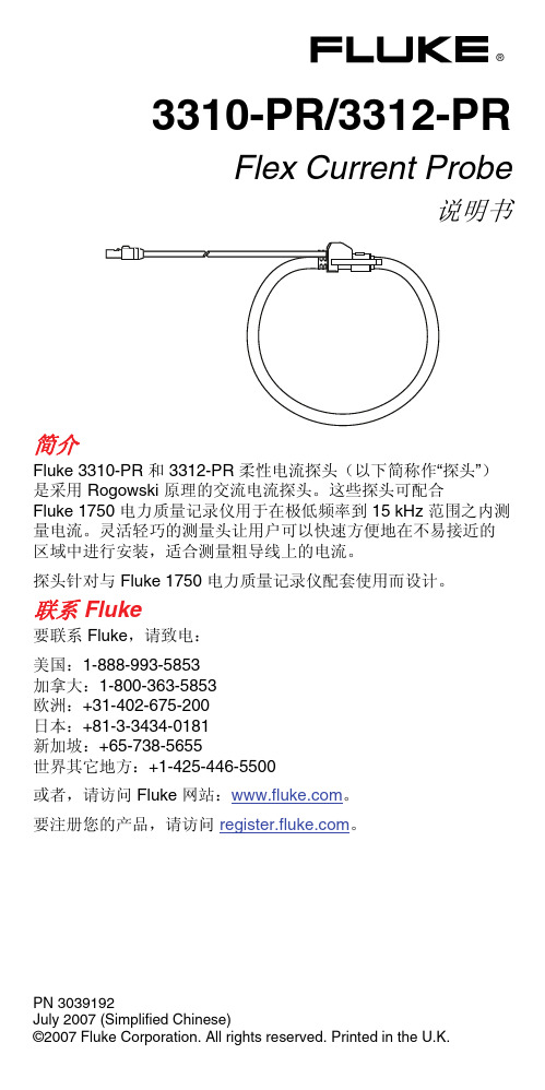
简介
Fluke 3310-PR 和 3312-PR 柔性电流探头(以下简称作“探头”) 是采用 Rogowski 原理的交流电流探头。这些探头可配合 Fluke 1750 电力质量记录仪用于在极低频率到 15 kHz 范围之内测 量电流。灵活轻巧的测量头让用户可以快速方便地在不易接近的 区域中进行安装,适合测量粗导线上的电流。 探头针对与 Fluke 1750 电力质量记录仪配套使用而设计。
12.4 mm (0.49 in.)
传感器弯曲半径(最小) 输出电缆 输出接头
38.1 mm (1.5 in.) 双芯屏蔽,3 m 长 LEMO 6 针公头连接器
工作温度范围 存放温度范围 工作湿度
-20 °C 至 +90 °C(-4 °F 至 +194 °F) -40 °C 至 +105 °C(-40 °F 至 221 °F) 15 % 至 85 %(非冷凝)
Fluke 公司保证本产品从购买之日起一年内,其材料和工艺均无任 何缺陷。本项保证不包括保险丝、一次性电池,或者因意外、疏 忽、误用、改装、污染及非正常情况下的操作或处理而造成的损 坏。经销商无权以 Fluke 的名义提供其它任何保证。若要在保修 期内获得保修服务,请与您最近的 Fluke 授权服务中心联系,以 获取有关产品退还的授权信息,并将产品及故障说明寄至该服务 中心。 本项保证是您唯一可以获得的补偿。除此以外,Fluke 不作其它任 何明示或隐含的保证,例如适用于某一特殊目的的隐含保证。 FLUKE 不应对基于任何原因或推测的任何特别、间接、偶发或后 续的损坏或损失负责。由于某些州或国家不允许将隐含保证或偶 发或后续损失排除在外或加以限制,故上述的责任限制或许对您 不适用。
福禄克高端手持表介绍

Fluke Core Values
• • • • • • The best team wins Customer talk, we listen Continuous improvement is our way of life Innovation defines our future Result matter Our customer has the right to get a little more than they paid for
温度对绝缘电阻的影响有多大? 温度的改变,会使绝缘电阻以指数曲线的函数关系随之该表。温度每上升10℃, 绝缘电阻值降低一倍;温度每下降10℃,绝缘电阻值增大一倍(粗略估计)。也 就是如果在40℃下测得点绝缘电阻是1MΩ,在20℃下测得的绝缘电阻大概是 4MΩ。
FQ&A
极化指数(PI)和介质吸收比(DAR) 这类测试方法的最大优势在于,环境温度对测量结果没有影响,只要在测量过 程中环境温度没有发生急剧的变化,测量结果就不需要修正。另外这种方法即 使在没有历史记录的情况下,也可以判断绝缘的好坏。尽管如此,建议在定期的 预防性维护计划中,应该记录实际测得的绝缘电阻值以备日后参考。 PI=R10分钟/R1分钟 DAR=R60s/R15s
接地电阻测试仪
接地的定义及概念
电路、设备与大地或某一代替大地的导电体之间的导电链接,包括正 常和非正常连接。 接地实际分成两种形式:地线接地和设备接地。地线接地是将电路的 道路(零线或中心线)连接到大地上的接地极,设备接地是为了保证 建筑物内设备正常安全运行而进行的接地。 除非两种系统存在连接,否则应该相互隔离,其目的是防止雷击造成 的闪络而产生的电位差。 接地的目的除了保护人员、设施和设备外,还为故障电流、雷击、静 电放电、EMI和RFI信号及干扰提供一条安全释放的路径。
- 1、下载文档前请自行甄别文档内容的完整性,平台不提供额外的编辑、内容补充、找答案等附加服务。
- 2、"仅部分预览"的文档,不可在线预览部分如存在完整性等问题,可反馈申请退款(可完整预览的文档不适用该条件!)。
- 3、如文档侵犯您的权益,请联系客服反馈,我们会尽快为您处理(人工客服工作时间:9:00-18:30)。
准确度1%±4字
分辨率
量程400.0Ω
4000Ω
分辨率0.1Ω
1Ω
准确度1%±5字
通断测量
≤30Ω
启动电流
响应时间100毫秒
频率测量
量程5.0 - 500.0 Hz
准确度0.5%±5字
触发电平10 - 100 Hz≥5 A, 5 - 10 Hz, 100 - 500 Hz≥10 A
技术规格
准确度1.6%±6字(50-60 Hz) {40 A}
2.5%±8字(60-500 Hz) {40 A}
1.5%±5字(50-60 Hz) {600/1000 A}
2.5%±5 digit (60-500 Hz) {600/1000 A}
Crest Factor和2%到规格为CF > 23.0 Max @ 500 A, 2.5 Max @ 600 A, 1.4 Max @ 1000 A
数字钳形表重量
384g (包括电池)
自动量程
Ohms
安全
CE
EN/IEC 61010-1和IEC 61010-2-032
安装类别III, 600V工作环境
Fluke319钳形电流表福禄克
Fluke317/319真有效值交直流数字钳形表/电流表
Fluke317/319真有效值交直流数字钳型表具有符合人体工程学的设计,它流线型的外型更方便握在手中。这两款纤薄,坚固的数字式钳型电流表更加适合易于1000A电流测量(319)和在狭窄空间内使用。317和319拥有精确的40 A小量程。FLUKE 319数字式钳形电流表除了具备一系列的测试功能,还具备了启动电流和频率功能,方便进行电机和照明等设备的测量。
交流响应有效值
直流电流
量程40.00 A, 600.0 A, 1000 A
分辨率0.01 A, 0.1 A, 1 A
准确度1.6%±6字(40 A)
1.5%±5字(600/1000 A)
交流电压
量程600.0 V
分辨率0.1 V
准确度1.5%±5字(20-500Hz)
交流响应有效直
直流电压
量程600.0 V
独特的40A小量程、高准确度电流测试--0体型轻便,更加适合易于在狭窄空间内使用
大型的背光显示屏,便于在黑暗的环境下读数
启动电流功能(319),可以测量诸如电机和照明等设备的启动电流
电流频率测量
数字钳形表精确度高于0.01A和0.1V
1000A交流/直流电流测量(319)
数字显频
6000字分辨率
电池低电量指示
电池低电量指示
电源
3颗AAA IEC LR03电池
数字钳形表钳口开度
1.45 in (37 mm)
钳开口度
1.45 in (37 mm)
数字钳形表尺寸(长X宽X高)
6.39 in x 2.29 in x 1.20 in
(162.4 mm x 58.25 mm x 30.5 mm)
600V交流/直流电压测量
4000Ω电阻测量
数字钳形表灵敏的通断测量
自动关机功能,最大限度地延长电池的使用寿命,从而在需要时仪表可以工作
显示保留功能,可把测量结果保留在屏幕上
一年保修期
319技术指标
交流电流
量程40.00 A, 600.0 A, 1000 A
分辨率0.01 A, 0.1 A, 1 A
