JBL_225W大功率低音炮电路图
NE5532LM3886力度十足的低音炮音响电路图
NE5532LM3886力度十足的低音炮音响电路图
力度十足的低音炮
在音乐的重放中,完美的低音再现,不仅能增强音乐感,更能增加临场感与真实感。
本文介绍一款体积不大但劲量十足的有源低音炮,它十分适合应用在多媒体电脑的音响系统中,或在家居面积较小的环境下欣赏音乐之用,使你轻松地浸泡在音乐里、溶入游戏中,体味那真实的感觉。
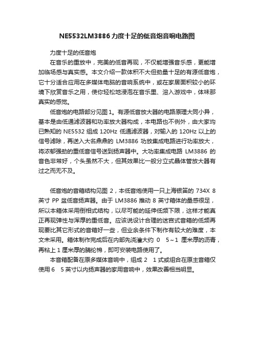
低音炮的电路部分见图1。
有源低音放大器的电路原理大同小异,基本是由低通滤波器和功率放大器构成,本电路也不例外,由大家均已熟知的NE5532组成120Hz 低通滤波器,对输入的120Hz以上的信号滤除,再送入大名鼎鼎的LM3886功放集成电路进行功率放大,将浓郁强劲的重低音信号送到扬声器中。
大功率集成电路LM3886的音色非常好,个头虽然不大,但其效果比一般分立式晶体管放大器有过之而无不及。
低音炮的音箱结构见图2,本低音炮使用一只上海银笛的734X 8英寸PP盆低音扬声器。
由于LM3886推动8英寸箱体的量感很足,所以本箱体采用倒相式结构,以尽可能的延伸低频下限,这样才能真正再现弹性与浑厚的重低音。
应该说设计合理的迷宫式音箱的低频再现要比其它形式的音箱好一些,但业余条件下制作有较大的难度,本文未采用。
箱体制作完成后在内部先浇灌大约05~1厘米厚的沥青,再粘上1厘米厚的腈纶棉,即可安装电路使用了。
本音箱配备在原多媒体音响中,组成21式或组合在原主音箱仅使用65英寸以内扬声器的家用音响中,效果改善相当明显。
音响用辅助电路
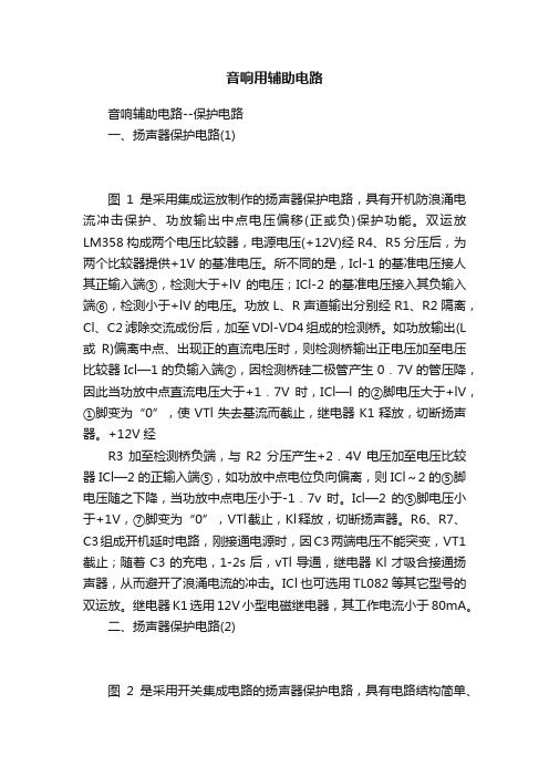
音响用辅助电路音响辅助电路--保护电路一、扬声器保护电路(1)图1是采用集成运放制作的扬声器保护电路,具有开机防浪涌电流冲击保护、功放输出中点电压偏移(正或负)保护功能。
双运放LM358构成两个电压比较器,电源电压(+12V)经R4、R5分压后,为两个比较器提供+1V的基准电压。
所不同的是,Icl-1的基准电压接人其正输入端③,检测大于+lV的电压;ICl-2的基准电压接入其负输入端⑥,检测小于+lV的电压。
功放L、R声道输出分别经R1、R2隔离,Cl、C2滤除交流成份后,加至VDl-VD4组成的检测桥。
如功放输出(L 或R)偏离中点、出现正的直流电压时,则检测桥输出正电压加至电压比较器Icl—1的负输入端②,因检测桥硅二极管产生0.7V的管压降,因此当功放中点直流电压大于+1.7V时,ICl—l的②脚电压大于+lV,①脚变为“0”,使VTl失去基流而截止,继电器K1释放,切断扬声器。
+12V经R3加至检测桥负端,与R2分压产生+2.4V电压加至电压比较器ICl—2的正输入端⑤,如功放中点电位负向偏离,则ICl~2的⑤脚电压随之下降,当功放中点电压小于-1.7v时。
Icl—2的⑤脚电压小于+1V,⑦脚变为“0”,VTl截止,Kl释放,切断扬声器。
R6、R7、C3组成开机延时电路,刚接通电源时,因C3两端电压不能突变,VT1截止;随着C3的充电,1-2s后,vTl导通,继电器Kl才吸合接通扬声器,从而避开了浪涌电流的冲击。
ICl也可选用TL082等其它型号的双运放。
继电器K1选用12V小型电磁继电器,其工作电流小于80mA。
二、扬声器保护电路(2)图2是采用开关集成电路的扬声器保护电路,具有电路结构简单、反应灵敏迅速的特点。
TWH8778是高速开关集成电路,内部设有过压、过流、过热保护电路,工作稳定可靠;控制极触发电流极小,为50~100uA,触发电压约1.6v;输出驱动电流可达lA。
图2电路中,开机防浪涌电流冲击保护由延时电路R3、C3完成。
JBL SP5II SoundPoint系列扬声器爆炸视图电路图说明书
180-0030
LOGO JBL
N/A
WARRANTY CARD
170-0091
OWNER’S MANUAL SPII
220-0864
OUTER CARTON
220-0440
TEMPLATE
SP5II ROUGH-IN FRAME PART NO. RIF5
QTY. 1 1 1 1 1
4 1 1 1 1
WIRING DIAGRAM
EXPLODED VIEW
BAFFLE 1
பைடு நூலகம்
4 NETWORK
5 TWEETER
3 WOOFER
8
GRILLE 2
6 CLOTH
7 (4)
DOG 7 (4)
ITEM 1 2 3 4 5 6 7 8 9
10 11 12
PART NO.
DESCRIPTION
590-0279
BAFFLE SP5II
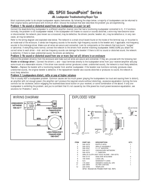
JBL SP5II SoundPoint® Series
JBL Loudspeaker Troubleshooting/Repair Tips
Most customers prefer to do simple loudspeaker repairs themselves. By following the steps below, a majority of loudspeakers can be returned to their original factory performance with minimum effort. Choose the example that best describes the problem you are experiencing. Problem 1: No sound or distorted sound from one loudspeaker in a pair (or set) Connect the dead/distorting loudspeaker to a different amplifier channel (one that had a functioning loudspeaker connected to it). If it functions normally, the problem is not loudspeaker-related. If the loudspeaker still makes no sound or sounds distorted, a wire may have become loose or disconnected, the network (also known as a crossover) may be defective, the drivers (woofer, tweeter, etc.) may be defective or, in very rare cases, all may be defective. Refer to the wiring diagram and exploded view below. The network is a small circuit board found on the inside of the terminal cup, or mounted to an inside wall of the enclosure. It sends low-frequency sounds to the woofer, high-frequency sounds to the tweeter and, if applicable, mid-frequency sounds to the midrange driver. Make sure all wires are secure and connected. Look for components on the network that look burnt, “bulged,” or abnormal. If everything looks normal, connect the network to the drivers from another matching loudspeaker. MAKE SURE you attach the correct wires to each driver – mid- and low-frequency sounds can damage the tweeter! If there is still no sound or distorted sound, the network is defective. If there is clean undistorted sound, the drivers are defective. Problem 2: No sound or distorted sound from one or more (but not all) drivers in an enclosure Remove the problem driver(s) from the enclosure and make sure all wires are secure and connected. If they are, proceed with the following test: Woofer or midrange driver – Connect the driver’s + and – input terminals directly to the loudspeaker wires from your receiver/amplifier and play some music at a reasonable volume. If the driver now sounds normal (produces a clean, undistorted sound), the network is most likely defective. Tweeter – Replace the tweeter with a functioning tweeter from another loudspeaker. If the tweeter now functions normally (produces clean, undistorted sound), the original tweeter is defective. If the replacement tweeter also sounds distorted or produces no sound, the network is most likely defective. Problem 3: Loudspeakers distort, rattle or pop at higher volumes This is usually NOT a loudspeaker problem. Common causes are too much power (playing the loudspeakers too loud and causing them to distort), an amplifier with not enough power (the amplifier can’t produce the required volume without distorting), excessive equalization (turning the tone controls too far clockwise, and/or engaging the loudness/bass boost button on your receiver) or some combination of the above. If only one loudspeaker is exhibiting the problem, and you’re confident that it’s not caused by too little power/too much power/excessive equalization, see solutions for Problems 1 and 2.
低音炮电路的设计讲解
郑州科技学院《模拟电子技术》课程设计题目低音炮电路的设计学生姓名魏11级通信工程(2)班专业班级学号信息工程学院(系)院指导教师2013-5-31 完成时间目录1 课程设计的目的 (12)课程设计的任务与要求............................................................... 12.1设计任务............................................................................. 12.2 设计要求............................................................................. 13 设计方案与论证........................................................................... 24 元件的选用................................................................................... 44.1 LM386芯片.. (4)4.2 扬声器.............................................................................................. 64.3变压器.............................................................................................. 75 硬件的制作与调试....................................................................... 75.1 电烙铁的使用................................................................................ 75.2 电子产品的调试............................................................................ 86 总结................................................................................................. 9参考文献............................................................................................ 11附录一:总体电路原理图............................................................... 12附录二:元器件清单.. (13)1 课程设计的目的现在的社会需要的就是人才,能给公司带来经济效益的人才,而大学生在大学中学习多种与本专业有关的课程,能更加完善自身。
低音炮电路

低音炮电路很多发烧友普遍使用6.5~8英寸低音单元的音箱,这些音箱的低频下限比较低,低音听起来虽然有力,但能量和延伸能力却不足。
众所周知,低音是音乐信号的基础,它在很大程度上影响听音的氛围,缺失低音信号声音会显得轻飘而不真实,而在正规的家庭影院播放中,超重低音箱是很重要的一分子,如果少了重低音的烘托,那就完全失去临场感,也就是说不真实。
因此,笔者建议,如果有条件,还是选用中大型落地箱为好,以得到更丰富的低频响应,而组建家庭影院时,应把超重低音音箱考虑进去。
当然,如果原来的系统没有丰富的低频效果,你也可单独添置一个优质的超重低音音箱来提高重播效果。
不过,好一点的超重低音音箱售价不菲,既然我们有能力去自己设计制作书架箱或落地箱,那么我们是否也能自己做一个好一点的超重低音音箱呢?答案是肯定的,有兴趣的读者不妨跟随着我依葫芦画瓢。
理想的超重低音箱的概念在制作前,我们应对什么是“好一点的超重低音音箱”有一个基本的概念。
笔者认为衡量超重低音音箱的品质高低有几个方面。
1、不好的超重低音箱必须就是有源压缩的所谓“有源放大”就是内置功放的,而无源超低音音箱是没有内置功放,箱内只有无源分频器,要和主音箱共用或另配功放。
无源超低音音箱是利用前级的音量控制来决定音量,如果超重低音音箱的灵敏度或音量和主音箱不平均值,可以引起声场纷乱、频响不平衡、声像定位没人等情况,而此时超重低音音箱的摆位又无法化解这一问题,这些问题就难以提升。
加之逊于低音小口径单元的振动质量确实大于主音箱单元,故表达意见速度必须快一些,提了这种超重低音音箱之后,效果往往很混浊。
有源逊于低音音箱就是专门为低音重播而设计的。
它的工作特征就是信号进袭具有源分频的前级。
100hz以下的频率由专用的低音放大器压缩后驱动逊于低音音箱。
100hz以上的频率经分频后送来至放大器,压缩后由主音箱播映。
这时必须存有一个单一制的音量控制用以掌控逊于低音音量跟主音箱在音量上的比例。
超重低音音箱制作(精)

超重低音有源音箱门宏为提高现有音响设备的听音效果,增加一只超重低音有源音箱,组成3D放音系统,往往可以取得事半功倍的效果。
由于150Hz以下的低音波长很长,不具有明显的方向性,因此,用一只超重低音音箱与原有立体声音响设备相配合,即可欣赏到具有超重低音震撼力的影音节目。
本文介绍一款结构简单、制作容易、工作稳定、效果良好的超重低音有源音箱,供爱好者自制。
一、电路简要工作原理超重低音有源音箱电路见图1,它包括低通滤波器、缓冲放大器和功率放大器三大部分。
取自原音响系统左、右音箱的L、R声道音频信号,经R1、R2混合后进入低通滤波器。
由于R1、R2阻值很大,又是从扬声器端接取信号,所以不会对左、右声道的立体声分离度产生不良影响。
电阻R3~R5、电容C1 ~C3、集成运放IC1-1等构成三阶巴特沃兹有源低通滤波器,具有每倍频程18dB的阻带衰减特性,转折频率为120Hz,将音频信号中的中高频成分滤除,只允许120Hz以下的低音信号通过。
集成运放IC1-2构成放大倍数为10倍的缓冲放大器,既隔离了功放电路对有源滤波器的影响,又提高了驱动电压。
IC2为功放集成电路,输出功率100W,完全能够满足家庭听音条件下对超重低音效果的要求。
电位器RP用于控制超重低音音量的大小。
以上电路采用±15V和±38V电源电压。
电源电路见图2,这是一个典型的整流滤波电源,其中,±15V电压是分别从±38V电压经简单稳压后获得的。
二、元器件选择有源低通滤波器IC1-1和缓冲放大器IC1-2,采用双运放集成电路TL082或LF353,该集成电路内含两个完全一样的运算放大器(图3,其输入级采用结型场效应管,具有很高的输入阻抗和较低的噪声系数。
功率放大器IC2采用傻瓜型功放集成模块“皇后”AMP1200,额定输出功率为100W,仅有输入、输出、正电源、负电源和地5个引脚(图4,使用极为方便。
如不需要如此大的输出功率,也可采用“傻瓜”175(输出功率75W或150(输出功率50W集成功放模块。
解析5种二分频扬声器电路
解析5种二分频扬声器电路在现代人类社会的生产活动中,经常需要将各种声音信号转换成电信号,然后进行储存、放大后再输出。
音频是指人耳能够感知的声音频率范围,电子分频是指对人能感知的声音频率分别进行低、中、高音的放大。
音频功率放大则是指音频电信号被放大以后,还要能够有足够大的功率去推动扬声器或耳机等负载,重新将电信号转换为声音输出。
电子分频电路在实际生活中具有很大的应用空间,它将各个频段的声音信号分离开来,合理的分割个单元的工作频段、进行个单元功率分配,使得个单元之间具有恰当的相位关系以减少各单元在工作中出现的声干涉失真。
另外,利用电子分频电路的特性还可以弥补单元在某频段里的声音缺陷,将各频段圆滑平顺地对接起来。
5种二分频扬声器电路所谓二分频扬声器电路就是在一只音箱中设有高音扬声器和中、低音扬声器。
高音扬声器的高频特性好、低频特性差,即它重放高音的效果好,重放中音和低音的效果差,让功率放大器输出的高音频信号通过高音扬声器重放出高音,让低音扬声器(习惯称法)重放中音和低音,采用这种分频重放方式还原高、中、低音,效果比单独使用一只扬声器好。
电路之一图4-93所示是最简单的二分频电路,电路中的BL1是低音扬声器,BL2是高音扬声器。
这一电路中没有分频元件,这是因为高音扬声器采用压电式扬声器,这种扬声器的高频特性好,阻抗高,这样BL2用来重放高音,BL1重放中音和低音。
图4-93 最简单的二分频电路对于中频和低频信号而言,由于BL2的阻抗较高,BL2相当于开路。
对于高频信号而言,BL1的高频特性差,而BL2的高频特性好,这样高频信号由BL2来重放。
电路之二图4-94所示是常见的二分频扬声器电路,电路中的BL1是低音扬声器,BL2是高音扬声器,C1是分频电容(采用无极性分频电解电容),通过适当选取分频电容C1的容量值,使C1只让高频段信号通过,不让中频、低频段信号通过,这样BL2就重放高音,中音和低音由BL1重放,从而实现了二分频重放。
通用2.1多媒体音箱电路图附讲解
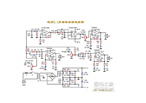
工作原理,如图纸所示:主要分为三部分。
分别为电源电路、卫星箱功放电路、超重低音电路.一、电源电路(图纸的最下面部分):220V市电经过保险管(F),和开关S后进入变压器初级,变压器的次级输出双12V交流,双12V送入由VD1组成的桥式整流电路电路,经过桥式整流和C14,C15(3300UF/25V)的滤波后,输出的空载电压约为正负16V左右(根号2乘于12V),即A+为正16V,A-为负16V。
正负16V为三块功放芯片TDA2030,UTC2030提供电源。
另一路经过R21、R22的降压后,由B+,B-输出约正负12V为低音前置放大和低通滤波器IC4提供电源电压。
在本图纸当中,前置放大的供电并没有采用78/7912三端稳压电路,磨机爱好者在更换两个3300UF电容时,也可以考虑加入LM7812/7912为前置提供更为稳定的工作电压。
二、左右声道放大电路(卫星箱功放电路),因左右声道作原理完全一致。
这里我只以图纸的左声道为例,作个介绍。
如图:RIN为信号输入端,经过耦合电容C23进入音量电位器,(音量电位器由三个引脚,与C23连接的是输入端,输出端也叫滑动端、另一引脚为接地端),调整音量后信号进入由R1/C3组成的高音提升电路,此电路可以提升一定量的高频信号,使声音更加清晰。
尔后信号经过耦合电容C1进入左声道功放,型号为UTC2030的1脚,经过功率放大后,由2030的第四脚输出,推动卫星箱发声。
图中的R7为反馈电阻,R7/R9为决定2030芯片的放大倍数。
因此,调整R7的阻值,就可以调整放大倍数。
R11/C7为扬声器补偿网络。
三、超低音电路。
由左右声道经两个10K电阻R5、R6后至C11耦合电容,尔后信号进入IC4,型号为JRC4558的3脚,图中IC4A为超低音的前置放大器。
R201T将此放大器的放大倍数设置为6倍左右。
(R17/R18),经过前置放大后,才能保证足够大的驱动电压,获得足够大的音量。
- 1、下载文档前请自行甄别文档内容的完整性,平台不提供额外的编辑、内容补充、找答案等附加服务。
- 2、"仅部分预览"的文档,不可在线预览部分如存在完整性等问题,可反馈申请退款(可完整预览的文档不适用该条件!)。
- 3、如文档侵犯您的权益,请联系客服反馈,我们会尽快为您处理(人工客服工作时间:9:00-18:30)。
Balboa™ Series SUB10 Powered Subwoofer Service ManualJBL Consumer Products250 Crossways Park Dr.Woodbury, New York 11797 Rev0 10/2006- CONTENTS -BASIC SPECIFICATIONS (1)PACKING (2)DETAILED SPECIFICATIONS (3)CONNECTIONS (5)OPERATION (7)TEST SET-UP AND PROCEDURE (8)EXPLODED VIEW/PARTS LIST (9)AMPLIFIER BLOCK DIAGRAM (10)DETAILED TROUBLESHOOTING (12)ELECTRICAL PARTS LIST (13)P.C.B. DRAWINGS (17)IC/TRANSISTOR PINOUTS (23)SCHEMATICS (24)BALBOA SUB10 SPECIFICATIONSAmplifier Power (RMS): 100 WattsPeak Dynamic Power *: 225 Watts(254mm)Driver: 10"Inputs: Line Level and LFECrossover Frequency: Variable from 50Hz to 150Hz, 24 dB per octave Frequency Response: 30Hz – 150HzDimensions (H x W x D): 19-3/4" x 14-1/16" x 14-3/4"(502mm x 357mm x 375mm)lb/16kgWeight: 35JBL continually strives to update and improve existing products, as well as create new ones. The specifications and details in this and related JBL publications are therefore subject to change without notice.* The Peak Dynamic Power is measured by recording the highest center-to-peak voltage measured across the output of a resistive load equal to minimum impedance of the transducer, using a 50Hz sine wave burst, 3 cycles on, 17 cycles off.Balboa Sub 10100W Powered Sub/ Plate AmpLINE VOLTAGE Yes/No Hi/Lo Line Unit Notes US 120VAC/60Hz Yes108-132VrmsNormal OperationEU 230VAC/50-60Hz Yes207-254Vrms Normal Operation Normal operation, MOMS required Parameter Specification Unit QA Test Limits Conditions NotesAmp SectionType (120V Model)AB AB N/A120V System is Class ABType (230V Model)G H N/A230V System is Class GLoad Impedance (speaker)4Ohms N/A NominalSystem average impedance8.2Ohms Reference Measured with AP using the ratiomethod, sweeping with an ext. amp 10 to500 HzAverage on the operating BW from 10 to500HzRated Output Power 120V100Watts95@ Nominal input voltage Rated Output Power 230V105Watts100@ Nominal input voltageAvgerage value - RMSDynamic power103Watts Reference@ Nominal input voltage 3/20 50 Hz Burst unit driven 6dB above the sensitivity to drive it into max power, measured value is the average of the 4 first consecutive peaksDynamic power HP134Watts Reference@ Nominal input voltage Highest RMS of the first 4 consecutive peaksTHD@ Rated Power0.5%122K filter THD @ 1 Watt0.1%0.322K filterDC Offset10mV-DC50@ Speaker Output Damping factor>150DF100Measured at amplifier board speaker out terminals, Output power 90 Watts THD < 0.1 %Input SensitivityInput Frequency50Hz50Nominal Freq.Line Input (L&R)15mVrms±2dB To 1 Watt Single input driven 1 input driven LFE Input9.5mVrms±2dB To 1 Watt LFE input driven onlySystem Gain-L and R inputs42.27dB±2dB Gain=130Single input driven L or R Signal to NoiseSNR-A-Weighted90dBA85To Rated power A-Weighting filterSNR-unweighted85dBr80To Rated power 22KHz filterSNR @ 1W-unweighted65dBr60To 1 Watt22KHz filterResidual Noise Floor1mVrms(max) 1.5Volume @max, w/ A/P Swept Bandpass Measurement (Line freq.+ harmonics)Input ImpedanceLine input L&R , LFE>10K ohms N/A Nominal over the audio BW Reference only FiltersLow Pass (fixed or variable)Variable--±2dB 2nd order variable + 2nd order fix, Range 50-110 HzSubsonic filter (HPF)Fixed±2dBFriend circuit Fixed±2dBLimiter (yes/no)YES--N/ATHD at Max. Output Power N/A--N/AFeaturesLFE Input YES Functional BW Limited to 500 Hz, Phase Switch (yes/no)YES--FunctionalVolume pot Taper (lin/log)LOG--FunctionalLP Variable Crossover contro YES Functional Range 50-110 HzATO YES Functional fsInput ConfigurationLine In (L,R)L ,R--Functional RCA inputs: RED-WHT, L , R Summed to MonoLine level in LFE LFE Functional Single connector Signal Sensing (ATO)Auto-Turn-On (yes/no)YES--FunctionalATO Input Frequency50Hz Functional ATO Level Line Level in (L,R 1.5mV Functional 2mV@50Hz into Line Input w/ 1 ch. drivenParameter Specification Unit QA Test Limits Conditions NotesATO Turn-on time< 1Sec Functional Amp connected and AC on, then input signal appliedAuto Mute/ Turn-OFF Time10minutes Functional T before muting, after signal is removed Auto turn of time (T) must be 5 > T <15 Power on Delay time3sec.Functional AC Power AppliedTransients/PopsATO Transient5mV-peak10@ Speaker OutputsTurn-on Transient50mV-peak100@ Speaker Outputs AC Line cycled from OFF to ONTurn-off Transient50mV-peak100@ Speaker Outputs AC Line cycled from ON to OFF EfficiencyStand-by Input Power13Watts14@ nom. line voltage Unit active, nosignal applied (Green LED)Maximum allowable input power undernominal Input voltage and frequency, HOTor COLD operation.Power Cons/Amps.@ratedpower 120V Model192 / 1.89 Watts/Amps208 / 2.00@ 120V-60 Hz (Nom.line voltage)100 Watts @ 4 Ohms nominal line voltage Power Cons/Amps.@ratedpower230V Model208 / 1.1Watts/Amps210 / 1.2@ 230V-50 Hz (Nom.line voltage)100 Watts @ 4 Ohms nominal line voltage ProtectionShort Circuit Protection YES--Functional Direct short at outputThermal Protection 65 deg. C--Functional@1/8 max unclipped Power Temperature rise should not exceed 35K riseDC Offset Protection YES--Functional DC present at Speaker Out leads Relay or crowbar (for driver/fire protection) Line Fuse Rating120VAC 2.5Amps Type-T or Slo Blo External fuse with UL/SEMKO rated holder 230VAC 1.25Amps Type-T or Slo Blo External fuse with UL/SEMKO rated holderCONTROLS AND CONNECTIONS Rear Panel0Subwoofer-Level Control 1Crossover Adjustment2Phase Switch3LFE Input4Line-Level Inputs5Power Indicator LED6Power SwitchSUBWOOFER CONNECTIONS Choose the Subwoofer Connection That Is Most Suitable for YourReceiver/ProcessorIf you have a Dolby®Digital or DTS®receiver/processor with a low-frequency-effects (LFE) or subwoofer output: If your receiver/processor does not contain a Dolby Digital or DTS processor but has a subwoofer output:NOTE: Some receivers have one subwoofer output.In that case, it is recommended that you use a Y connector (not included)to maximize performance.Power OnPlug your subwoofer’s AC cord into a wall outlet. Do not use the outlets on the back of the receiver.Initially set the Subwoofer-Level Control ¡to the “min” position.Turn on your sub by pressing the Power Switch ¶on the rear panel.Turn on your entire audio system and start a CD or movie soundtrack at a moderate level.Auto On/StandbyWith the Power Switch ¶in the ON position, the LED §on the rear panel will remain lit in red or green to indicate the On/Standby mode of the subwoofer.RED = STANDBY (no signal detected, amp off)GREEN = ON (signal detected, amp on)The subwoofer will automatically enter the Standby mode after approximately 10 minutes when no signal is detected from your system. The subwoofer will then power ON instantly when a signal is detected. During periods of normal use, the Power Switch ¶can be left on. You may turn off the Power Switch ¶for extended periods of nonoperation, e.g., when you are away on vacation.Adjust LevelTurn your Subwoofer-Level Control ¡up to the “5” position (halfway). If no sound emanates from the subwoofer, check the AC-line cord and input cables. Are the connectors on the cables making proper contact? Is the AC plug connected to a “live”receptacle? Has the Power Switch ¶been pressed to the “On”position? Once you have confirmed that the subwoofer is active,proceed by playing a CD, record or cassette. Use a selection that has ample bass information.Set the overall volume control of the preamplifier or stereo to a comfortable level.Adjust the Subwoofer-Level Control ¡until you obtain a pleasing blend of bass. Bass response should notoverpower the room but rather be adjusted so there is a harmonious blend across the entire musical range. Many users have a tendency to set the subwoofer volume too loud, adhering to the belief that a subwoofer is there to produce lots of bass. This is not entirely true. A subwoofer is there to enhance bass, extending the response of the entire system so the bass can be felt as well as heard. However,overall balance must be maintained or the music will not sound natural. An experienced listener will set the volume of the subwoofer so its impact on bass response is always there but never obtrusive.Phase ControlThe Phase Switch £determines whether the subwoofer speaker’s piston-like action moves in and out with the main speakers (0˚), or opposite the main speakers (180˚).Proper phase adjustment depends on several variables such as room size, subwoofer placement and listener position. Adjust the phase switch to maximize bass output at the listening position.Crossover AdjustmentsThe Crossover Adjustment Control ™determines the highest frequency at which the subwoofer reproduces sounds. If your main speakers can comfortably reproduce some low-frequency sounds,set this control to a lower frequency setting, between 50Hz and 100Hz. This will concentrate the subwoofer’s efforts on the ultradeep bass sounds required by today’s films and music. If you are using smaller bookshelf speakers that do not extend to the lower bass frequencies, set the Crossover Adjustment Control to a higher setting, between 120Hz and 150Hz.N O T E :This control will have no effect if the LFE Input ¢is used. If you have a Dolby Digital or DTS processor/receiver, the Low-Pass Frequency is set by the processor/receiver. Consult your owner’s manual to learn how to view or change this setting.OPERATIONBALBOA series SUB10BALBOA SUB10 Test Set Up and ProcedureSYSTEM AURAL SWEEP TEST Equipment needed:• Function/signal generator/sweep generator • Integrated Amplifier • Multimeter• Speaker cablesGeneral Unit Function (UUT = Unit Under Test)Switches/knobs on the amplifier faceplate:Low Pass Frequency Adjust full CW (150Hz) Phase switch – either position1. From the signal generator, Connect both right and left line level inputs (RCA) – not the LFE jack - to signalgenerator and UUT. Use Y-cable if necessary from mono source. 2. On the amplifier, turn the LEVEL control full Counterclockwise (Min). 3. Turn on generator, adjust to 100mV, 50 Hz .4. Plug in UUT; turn the power switch ON. Turn LEVEL control full Clockwise (Max).5. LED should now be Green; immediate bass response should be heard and felt from rear port tube opening.6. Turn off generator, turn LEVEL control fully Counterclockwise (Min), disconnect RCA cable.Sweep Function1. Follow steps 1-6 above, using a sweep generator as a signal source.2. Sweep generator from 20Hz to 1kHz. Listen to the cabinet and drivers for any rattles, clicks, buzzes orany other noises. If any unusual noises are heard, remove woofer and test.Driver Function (Woofer)1. Remove woofer from cabinet; detach + and - wire clips.2. Check DC resistance of woofer; it should be3.3 ohms ±10%.3. Connect a pair of speaker cables to driver terminals. Cables should be connected to an integratedamplifier fed by a signal generator. Turn on generator and adjust so that speaker level output is 5.0V. 4. Sweep generator from 20Hz to 1kHz. Listen to driver for any rubbing, buzzing, or other unusual noises.BALBOA series SUB10BALBOA series SUB10EXPLODED VIEWBALBOA SUB10 (UL) AMP Troubleshooting Flow ChartBALBOA series SUB10BALBOA series SUB10BALBOA series SUB10BALBOA series SUB10BALBOA series SUB10BALBOA series SUB10BALBOA series SUB1024BALBOA series SUB10BALBOA series SUB1026。