低音炮电路图
JBL_225W大功率低音炮电路图

Balboa™ Series SUB10 Powered Subwoofer Service ManualJBL Consumer Products250 Crossways Park Dr.Woodbury, New York 11797 Rev0 10/2006- CONTENTS -BASIC SPECIFICATIONS (1)PACKING (2)DETAILED SPECIFICATIONS (3)CONNECTIONS (5)OPERATION (7)TEST SET-UP AND PROCEDURE (8)EXPLODED VIEW/PARTS LIST (9)AMPLIFIER BLOCK DIAGRAM (10)DETAILED TROUBLESHOOTING (12)ELECTRICAL PARTS LIST (13)P.C.B. DRAWINGS (17)IC/TRANSISTOR PINOUTS (23)SCHEMATICS (24)BALBOA SUB10 SPECIFICATIONSAmplifier Power (RMS): 100 WattsPeak Dynamic Power *: 225 Watts(254mm)Driver: 10"Inputs: Line Level and LFECrossover Frequency: Variable from 50Hz to 150Hz, 24 dB per octave Frequency Response: 30Hz – 150HzDimensions (H x W x D): 19-3/4" x 14-1/16" x 14-3/4"(502mm x 357mm x 375mm)lb/16kgWeight: 35JBL continually strives to update and improve existing products, as well as create new ones. The specifications and details in this and related JBL publications are therefore subject to change without notice.* The Peak Dynamic Power is measured by recording the highest center-to-peak voltage measured across the output of a resistive load equal to minimum impedance of the transducer, using a 50Hz sine wave burst, 3 cycles on, 17 cycles off.Balboa Sub 10100W Powered Sub/ Plate AmpLINE VOLTAGE Yes/No Hi/Lo Line Unit Notes US 120VAC/60Hz Yes108-132VrmsNormal OperationEU 230VAC/50-60Hz Yes207-254Vrms Normal Operation Normal operation, MOMS required Parameter Specification Unit QA Test Limits Conditions NotesAmp SectionType (120V Model)AB AB N/A120V System is Class ABType (230V Model)G H N/A230V System is Class GLoad Impedance (speaker)4Ohms N/A NominalSystem average impedance8.2Ohms Reference Measured with AP using the ratiomethod, sweeping with an ext. amp 10 to500 HzAverage on the operating BW from 10 to500HzRated Output Power 120V100Watts95@ Nominal input voltage Rated Output Power 230V105Watts100@ Nominal input voltageAvgerage value - RMSDynamic power103Watts Reference@ Nominal input voltage 3/20 50 Hz Burst unit driven 6dB above the sensitivity to drive it into max power, measured value is the average of the 4 first consecutive peaksDynamic power HP134Watts Reference@ Nominal input voltage Highest RMS of the first 4 consecutive peaksTHD@ Rated Power0.5%122K filter THD @ 1 Watt0.1%0.322K filterDC Offset10mV-DC50@ Speaker Output Damping factor>150DF100Measured at amplifier board speaker out terminals, Output power 90 Watts THD < 0.1 %Input SensitivityInput Frequency50Hz50Nominal Freq.Line Input (L&R)15mVrms±2dB To 1 Watt Single input driven 1 input driven LFE Input9.5mVrms±2dB To 1 Watt LFE input driven onlySystem Gain-L and R inputs42.27dB±2dB Gain=130Single input driven L or R Signal to NoiseSNR-A-Weighted90dBA85To Rated power A-Weighting filterSNR-unweighted85dBr80To Rated power 22KHz filterSNR @ 1W-unweighted65dBr60To 1 Watt22KHz filterResidual Noise Floor1mVrms(max) 1.5Volume @max, w/ A/P Swept Bandpass Measurement (Line freq.+ harmonics)Input ImpedanceLine input L&R , LFE>10K ohms N/A Nominal over the audio BW Reference only FiltersLow Pass (fixed or variable)Variable--±2dB 2nd order variable + 2nd order fix, Range 50-110 HzSubsonic filter (HPF)Fixed±2dBFriend circuit Fixed±2dBLimiter (yes/no)YES--N/ATHD at Max. Output Power N/A--N/AFeaturesLFE Input YES Functional BW Limited to 500 Hz, Phase Switch (yes/no)YES--FunctionalVolume pot Taper (lin/log)LOG--FunctionalLP Variable Crossover contro YES Functional Range 50-110 HzATO YES Functional fsInput ConfigurationLine In (L,R)L ,R--Functional RCA inputs: RED-WHT, L , R Summed to MonoLine level in LFE LFE Functional Single connector Signal Sensing (ATO)Auto-Turn-On (yes/no)YES--FunctionalATO Input Frequency50Hz Functional ATO Level Line Level in (L,R 1.5mV Functional 2mV@50Hz into Line Input w/ 1 ch. drivenParameter Specification Unit QA Test Limits Conditions NotesATO Turn-on time< 1Sec Functional Amp connected and AC on, then input signal appliedAuto Mute/ Turn-OFF Time10minutes Functional T before muting, after signal is removed Auto turn of time (T) must be 5 > T <15 Power on Delay time3sec.Functional AC Power AppliedTransients/PopsATO Transient5mV-peak10@ Speaker OutputsTurn-on Transient50mV-peak100@ Speaker Outputs AC Line cycled from OFF to ONTurn-off Transient50mV-peak100@ Speaker Outputs AC Line cycled from ON to OFF EfficiencyStand-by Input Power13Watts14@ nom. line voltage Unit active, nosignal applied (Green LED)Maximum allowable input power undernominal Input voltage and frequency, HOTor COLD operation.Power Cons/Amps.@ratedpower 120V Model192 / 1.89 Watts/Amps208 / 2.00@ 120V-60 Hz (Nom.line voltage)100 Watts @ 4 Ohms nominal line voltage Power Cons/Amps.@ratedpower230V Model208 / 1.1Watts/Amps210 / 1.2@ 230V-50 Hz (Nom.line voltage)100 Watts @ 4 Ohms nominal line voltage ProtectionShort Circuit Protection YES--Functional Direct short at outputThermal Protection 65 deg. C--Functional@1/8 max unclipped Power Temperature rise should not exceed 35K riseDC Offset Protection YES--Functional DC present at Speaker Out leads Relay or crowbar (for driver/fire protection) Line Fuse Rating120VAC 2.5Amps Type-T or Slo Blo External fuse with UL/SEMKO rated holder 230VAC 1.25Amps Type-T or Slo Blo External fuse with UL/SEMKO rated holderCONTROLS AND CONNECTIONS Rear Panel0Subwoofer-Level Control 1Crossover Adjustment2Phase Switch3LFE Input4Line-Level Inputs5Power Indicator LED6Power SwitchSUBWOOFER CONNECTIONS Choose the Subwoofer Connection That Is Most Suitable for YourReceiver/ProcessorIf you have a Dolby®Digital or DTS®receiver/processor with a low-frequency-effects (LFE) or subwoofer output: If your receiver/processor does not contain a Dolby Digital or DTS processor but has a subwoofer output:NOTE: Some receivers have one subwoofer output.In that case, it is recommended that you use a Y connector (not included)to maximize performance.Power OnPlug your subwoofer’s AC cord into a wall outlet. Do not use the outlets on the back of the receiver.Initially set the Subwoofer-Level Control ¡to the “min” position.Turn on your sub by pressing the Power Switch ¶on the rear panel.Turn on your entire audio system and start a CD or movie soundtrack at a moderate level.Auto On/StandbyWith the Power Switch ¶in the ON position, the LED §on the rear panel will remain lit in red or green to indicate the On/Standby mode of the subwoofer.RED = STANDBY (no signal detected, amp off)GREEN = ON (signal detected, amp on)The subwoofer will automatically enter the Standby mode after approximately 10 minutes when no signal is detected from your system. The subwoofer will then power ON instantly when a signal is detected. During periods of normal use, the Power Switch ¶can be left on. You may turn off the Power Switch ¶for extended periods of nonoperation, e.g., when you are away on vacation.Adjust LevelTurn your Subwoofer-Level Control ¡up to the “5” position (halfway). If no sound emanates from the subwoofer, check the AC-line cord and input cables. Are the connectors on the cables making proper contact? Is the AC plug connected to a “live”receptacle? Has the Power Switch ¶been pressed to the “On”position? Once you have confirmed that the subwoofer is active,proceed by playing a CD, record or cassette. Use a selection that has ample bass information.Set the overall volume control of the preamplifier or stereo to a comfortable level.Adjust the Subwoofer-Level Control ¡until you obtain a pleasing blend of bass. Bass response should notoverpower the room but rather be adjusted so there is a harmonious blend across the entire musical range. Many users have a tendency to set the subwoofer volume too loud, adhering to the belief that a subwoofer is there to produce lots of bass. This is not entirely true. A subwoofer is there to enhance bass, extending the response of the entire system so the bass can be felt as well as heard. However,overall balance must be maintained or the music will not sound natural. An experienced listener will set the volume of the subwoofer so its impact on bass response is always there but never obtrusive.Phase ControlThe Phase Switch £determines whether the subwoofer speaker’s piston-like action moves in and out with the main speakers (0˚), or opposite the main speakers (180˚).Proper phase adjustment depends on several variables such as room size, subwoofer placement and listener position. Adjust the phase switch to maximize bass output at the listening position.Crossover AdjustmentsThe Crossover Adjustment Control ™determines the highest frequency at which the subwoofer reproduces sounds. If your main speakers can comfortably reproduce some low-frequency sounds,set this control to a lower frequency setting, between 50Hz and 100Hz. This will concentrate the subwoofer’s efforts on the ultradeep bass sounds required by today’s films and music. If you are using smaller bookshelf speakers that do not extend to the lower bass frequencies, set the Crossover Adjustment Control to a higher setting, between 120Hz and 150Hz.N O T E :This control will have no effect if the LFE Input ¢is used. If you have a Dolby Digital or DTS processor/receiver, the Low-Pass Frequency is set by the processor/receiver. Consult your owner’s manual to learn how to view or change this setting.OPERATIONBALBOA series SUB10BALBOA SUB10 Test Set Up and ProcedureSYSTEM AURAL SWEEP TEST Equipment needed:• Function/signal generator/sweep generator • Integrated Amplifier • Multimeter• Speaker cablesGeneral Unit Function (UUT = Unit Under Test)Switches/knobs on the amplifier faceplate:Low Pass Frequency Adjust full CW (150Hz) Phase switch – either position1. From the signal generator, Connect both right and left line level inputs (RCA) – not the LFE jack - to signalgenerator and UUT. Use Y-cable if necessary from mono source. 2. On the amplifier, turn the LEVEL control full Counterclockwise (Min). 3. Turn on generator, adjust to 100mV, 50 Hz .4. Plug in UUT; turn the power switch ON. Turn LEVEL control full Clockwise (Max).5. LED should now be Green; immediate bass response should be heard and felt from rear port tube opening.6. Turn off generator, turn LEVEL control fully Counterclockwise (Min), disconnect RCA cable.Sweep Function1. Follow steps 1-6 above, using a sweep generator as a signal source.2. Sweep generator from 20Hz to 1kHz. Listen to the cabinet and drivers for any rattles, clicks, buzzes orany other noises. If any unusual noises are heard, remove woofer and test.Driver Function (Woofer)1. Remove woofer from cabinet; detach + and - wire clips.2. Check DC resistance of woofer; it should be3.3 ohms ±10%.3. Connect a pair of speaker cables to driver terminals. Cables should be connected to an integratedamplifier fed by a signal generator. Turn on generator and adjust so that speaker level output is 5.0V. 4. Sweep generator from 20Hz to 1kHz. Listen to driver for any rubbing, buzzing, or other unusual noises.BALBOA series SUB10BALBOA series SUB10EXPLODED VIEWBALBOA SUB10 (UL) AMP Troubleshooting Flow ChartBALBOA series SUB10BALBOA series SUB10BALBOA series SUB10BALBOA series SUB10BALBOA series SUB10BALBOA series SUB10BALBOA series SUB1024BALBOA series SUB10BALBOA series SUB1026。
雅马哈YST-SW800

雅马哈YST-SW800低音炮电路图主要特点:25cm低音单元输出功率:800W尺寸:宽*高*深:390X482X420重量:25kg规格:Dual-Bias单个10英寸(25cm)多范围,超长Stroke设计,Dual- Bias系统内置1000瓦功放采用黑梣木、乙烯树脂材料具有磁遮蔽保护功能支持扬声器、Line、LFE输出体积:15-3/8" x 19" x 16 9/16"重量:52.9 磅YST-SW800内置采用先进技术的功率放大器,它不仅可以释放出更高的功率,而且还可以降低失真,减少功率损失。
另外它在电源上也有一些讲究。
雅马哈声称,YST-SW800所采用的开关装置在低音炮启闭的时候可以让电压和电流水平保持稳定不变,它还可以把噪音降低到只有常规电源开关的1/30 ,使电源稳定避免电源波动,大容量,低阻抗,操作无杂音等等,用户在使用时就会感受到的。
YST-SW800低音炮有一个可变低通分频(40-140Hz)以及多个相位控制。
其中的BASS (Bass Action Selector Switch)能够让用户在电影模式和音乐模式之间根据自己的爱好作出选择。
频率响应是18-160Hz (-10dB)。
虽然这不是音响市场上的第一只1000瓦低音炮,但是对雅马哈来说,却是他们的开山之作。
这里所标称的“1000瓦”就是实实在在的1000瓦(可不是像有些廉价的音响号称可以达到“1000瓦”)。
雅马哈所独有的YST(Yamaha Servo Technology)技术可以让音箱与功放很好的协同工作,对于线性音源能够消除阻抗,使得音质更加出色。
YST-SW800实质上是雅马哈生产的第一款“真正”针对家庭影院系统的低音炮。
过去他们所生产的低音炮采用的都是6-8英寸驱动单元(内置100瓦功放),这些产品对于放在卧室、宿舍等小地方还马马虎虎。
但是现在新推出的YST-SW800采用的是了10英寸的驱动单元(内置1000瓦功放),则可以让你的家庭影院系统大放异彩。
车载有源低音炮电路图 [收藏]
![车载有源低音炮电路图 [收藏]](https://img.taocdn.com/s3/m/8f6f6bc058f5f61fb7366688.png)
车载有源低音炮电路图[收藏]
上传者:dolphin 浏览次数:1405分享到:开心网人人网新浪微博EEPW微博
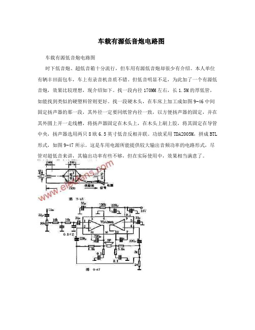
时下低音炮、超低音箱十分流行,但车用有源低音炮却很少有介绍。
本人单位有辆丰田面包车,车上有录音机音质不错。
但低音明显不足,为此加了一个有源低音炮,效果比较理想,现介绍如下。
找一段内径170MM左右,长1.5M 的厚低管,如能找到类似的硬塑料管则更好。
找一段硬木头,在车床上加工成如图9-46中间固定扬声器的那一段,其外径一定要同纸管内径一致,以方便扬声器的固定,并在其外圆上开一走线槽,将扬声器固定在木头上,在木头上刷上胶,将其固定在导管中央,扬声器选用两只8欧6.5英寸低音反相并联。
功放采用TDA2005M,拼成BTL 形式,如图9-47所示。
这是车用电源所能提供较大输出音频功率的电路形式,尽管对超低音来讲,其输出功率有些不够,但在实际使用中,效果相当满意了。
使用时将低音炮旋转在车后座下,低音信号可直接从扬声器上拾取,注意相位不要接错。
此低音炮如能配置50W 以上超低音功放、用于家庭影院系统,其效果也较好。
一款带通式低音炮的设计(图)

一款带通式低音炮的设计(图)
一、电路设计由图1可知,滤波电路是典型的巴特沃斯带通形式。
运放(IC1)选用LM833N,IC1-a与电阻R1、R9及电容C1、C2构成高通滤波器,IC1-b与电阻R4、R10及电容C3、C4构成低通滤波器,各自的截止频率分别由f高=1/2πR1C1和f低=1/2πR4C3计算,按图示值.高通截止频率为20Hz,低通截止频率为300Hz[注意,这两个截止频率各要大于C或小于)带通音箱高低端截止频率约一个倍频程,该低音炮高低截止频率分别为150Hz与40Hz]。
各滤波器的增益可由G高=R2/R3,G低=R5/R6调整,本电路设计为G高=G低=1.5(倍)。
功放选用LM3886TF(IC2),功放增益GA由R7/R8来确定。
另外,由于是专用低音功放,输出电流大,以致耗散功率较高,所以散热器要足够大,并在其与IC2的接触面上涂适量导热硅脂。
电源变压器采用160w、次级电压双26V加上双15V的环牛,功放滤波电容采用四只4700uF国产优质电解,运放的电源由双15V绕组经整流滤渡、稳压(7815、7915)后供给。
二、扬声器选取选用惠威的S8R云母碳化聚丙烯扬声器,其参考数据如下:口径8英寸,fs=28Hz,Po=60W,Qts=0.56,灵敏度89dB/W/m。
三、箱体设计该低音炮的尺寸及内部结构见图2,扬声器置于箱体内部,箱内上下两室用隔板隔开,扬声器下方是一密闭箱,其上方则是带排气口的反射式结构。
扬声器截止频率fs要与倒相管调谐频率相匹配,扬声器的Qts值也要与倒相箱Q值相等,并与密闭箱Q值相匹配,以取得合适的带通特性。
SUB低音炮功放电路

SUB低音炮功放电路
电源及保护电路
电源及保护电路中保护电路具有开机延时和主放大电路输出中点直流过压保护功能。
刚开机时保护电路供电电压经R29,R31支路向C18充电,开始时VT20基极电位低不能导通,导致VD10, VT21截止,继电器K1不能吸合,常开触点断开了功率级与扬声器的连接,避免了开机浪涌电流对扬声器的冲击。
随着C18充电电压的升高,VT20饱和导通,VD10, VT21也随之饱和导通,继电器K1吸合,接通扬声器正常放音。
R29, R31和C18决定开机延时时间的长短。
当功率输出级中点出现正或负的超过安全工作电压时,C16,C17充电,充电电压达到±0.6V以上时,VT18或VT19导通,两管集电极突现低电压导致C18放电,VT20截止,引起VT21也截止,继电器K1释放,断开扬声器,起到保护作用。
此过程中,由于C16, C17和C18容量较大,充放电时间较长,避免了保护电路对短暂超标电压的误动作。
SUB低音炮功放电路
更清晰电路,更多功放电路,功放方案,请打开以下链接查看!朋友!祝您成功!/item.htm?spm=a1z10.3.17.11.2d2fd1&id=16083434391& ,通过本链接,您可以拥有:DVD+功放一体机功放电路,AB类模拟功放,D类数字功放……等,涉及(2.0,2.1,3.1,4.0,5.1,A VR,SUB低音炮……等)家庭功放,汽车功放,专业功放,多媒体音箱……等,功率从几十瓦到几千瓦,输出从单声道到多声道,电路成熟稳定,多数是经过工厂批量生产成品直接输出,部分方案还包括了原理图,PCB图,BOM表……!
朋友!不要错过哦!。
ASW低音炮专用频率均衡放大器的设计制作音响电路图

ASW低音炮专用频率均衡放大器的设计制作音响电路图ASW低音炮专用频率均衡放大器的设计制作本放大器是为笔者的ASW低音炮度身定制的,具有简单可靠、性能优良、使用灵活等特点。
若将其均衡电路参数稍作修改,也适用于其他类型的超低频音箱。
现将其电路原理、制作及安装方法等介绍如下。
一、电路工作原理本放大器包括频率均衡、功率放大、电源等几个部分。
1、频率均衡电路10英寸单元ASW低音炮的低频下限选36Hz,这一指标已很不错,但重放36Hz以下的超低频时份量仍感不足,若使用的是8英寸或6.5英寸单元制作的超低频音箱,低频下限一般只能达到42Hz以上,重放超低频时更是捉襟见肘,力不从心。
这时听到的多半只是超低频的谐音。
故均有必要通过均衡电路预先对40Hz以下的超低频份量予以适当提升,以充分发挥音箱的潜能,改善重放效果。
此外,不同类型超低频音箱的低频上限也各不相同,与主音箱低频下限的配合也就不一定适当,可能造成系统中低频段的响应失真。
故也有必要通过均衡电路对超低频音箱的频率上限进行调整,使之能与主音箱的低频下限完美配合。
而20Hz以下的次低频人耳虽不可闻,但音乐信号中则可能存在(包括噪音),一旦进入音箱,单元锥盆的振幅极大,会产生大量可闻的失真信号(如调制失真、二次、三次谐波失真等),故也需要通过均衡电路予以衰减。
具有上述多种功能的均衡电路通常比较复杂。
为简化起见,本均衡电路选用了最为简单有效的高Q值高通有源滤波器加可调式无源低通滤波器的电路形式(见图1)。
图中,L、R声道信号经R1、R2相加(接解码器超低音输出端子时只需从一个输入端接入),再经音量电位器VR1调节后,送往IC1a与外围阻容元件组成的高Q值高通滤波器。
该滤波器在不同Q值时具有如图2所示的通带特性。
当Q>0.7时,其转折频率fp处会形成一个峰,Q越大,峰越高(提升量越大)。
利用这一特性,且Q值取得适当,便可按要求在提升超低频的同时衰减次低频,且电路十分简单,该滤波器的电路特点是具有等值的滤波元件C、R和一定的增益,且Q值通过电路增益A来控制,其中A=1+R4/R3Q=1/(3-A)Q值决定后,fp处的提升量也就决定了。
车载有源低音炮电路图
车载有源低音炮电路图车载有源低音炮电路图时下低音炮、超低音箱十分流行,但车用有源低音炮却很少有介绍。
本人单位有辆丰田面包车,车上有录音机音质不错。
但低音明显不足,为此加了一个有源低音炮,效果比较理想,现介绍如下。
找一段内径170MM左右,长1.5M的厚低管,如能找到类似的硬塑料管则更好。
找一段硬木头,在车床上加工成如图9-46中间固定扬声器的那一段,其外径一定要同纸管内径一致,以方便扬声器的固定,并在其外圆上开一走线槽,将扬声器固定在木头上,在木头上刷上胶,将其固定在导管中央,扬声器选用两只8欧6.5英寸低音反相并联。
功放采用TDA2005M,拼成BTL 形式,如图9-47所示。
这是车用电源所能提供较大输出音频功率的电路形式,尽管对超低音来讲,其输出功率有些不够,但在实际使用中,效果相当满意了。
使用时将低音炮旋转在车后座下,低音信号可直接从扬声器上拾取,注意相位不要接错。
此低音炮如能配置50W以上超低音功放、用于家庭影院系统,其效果也较好。
school)], 4 4 house building as well as more than 1000 copies of books, more than 10 kinds of collection of newspapers and magazines, fires burnt down. In 1938, the Japanese learned that the national Government established in XI Tang Tomb rotten "clip" taxes, tax officers live in 8 of Yan Dong village farmers home, troops at night, Yao was burned several houses. 1938 new morning of September 18, the Japanese team went to the countryside "sweep" from the kaiyang village line to Tung Yang Jia Qiao yan Temple wall and met Yang Jia溇 Zhou Dana (male) weeks because of long-term illness and can't work in the fields, the Japanese see his face from scratch without calluses, regard him as "Shina", thrust a knife at the scene of his death. The body was stabbed 7 times, wound 13. The same day, Trang bang village heard the Japanese come to "mop-up" are hiding, mother of 9 Zhou Guanbao Zhang Aying todrill a "dry mound", was discovered by the Japanese, a shot in the end. The same day, is 7 zhouhaijiangzhi grandfather Zhou Yingbao to escape the Japanese army, was found on the road, a shot in the end. In March 1939, the Japanese army in Yan Tomb raiding, has arrested 16 people, in fengqiao cigarettes this morning bang, killing 11 people on the River, East meeting point in wood qiaotu in the afternoon killing 4 people on the Riverside. Gu Tong is a Japanese go speak the Shanghai dialect,later to be called Gu Tong as "kill left." On January 18, 1943, theelves, five thousand or six thousand, water and land go hand in hand "mop-up" jiaxing area west of the railway, Yan Tomb area fall. March 6, Niu Shan (County Government II section chief) carrying its child Niu Jun (strict Tomb seventh district Chang) and the District Assistant Yu Xuchu, and players Jin Fuqin, and Shen Baosheng, six people received Wujiang underground County Government notification低成本超重低音炮电路及制作市售的国产有源超重低音音箱价格一般均在1200元以上,进口的产品售价更是价格不菲、本文向读者介绍一款自制的有源超重低音音箱,输出功率达100W,最低频率响应可达26HZ,制作成本500元左右。
TDA2030A BT大功率功放低音炮电路图

TDA2030A BT大功率功放低音炮电路图此功放是以集成电路TDA2030为中心组成的功率放大器,具有失真小、外围元件少、装配简单、功率大、保真度高等特点,很适合无线电爱好者和音响发烧友自制!套件采用4个TDA2030A组成双通道的BTL电路。
套件所用的电阻为金属膜电阻,小电解电容使用22UF,两个大滤波电容为4700UF/25V(实测耐压可达40v左右)小体积电解电容,其它电容采用金属化CBB无极性电容。
电路板设计精良,噪音小,美观大方,一推出就得到广大网友的喜爱。
既然是DIY 产品,就存在升级的地方,比如说将TDA2030A代换成1875表现可能会更出众。
之所以本站没有选用1875的原因是它的成本太高啦!“不惜成本,只求效果”的烧友可以将本板继续DIY一套音响成百上千是很正常的事!TDA2030A是目前性价比最高的功放集成块之一,内部有完善的过载及过热保护,是入门级功放制作的绝佳选择。
TDA2030A的工作电压范围较广,从±6~±22V都可以正常工作。
今天就让我们用TDA2030A来做一款BTL功放。
BTL电路的特点就是在相同的供电电压下,可以得到较普通功放两倍以上的输出功率(这一点音响爱好者都是知道的)。
下图为TDA2030A BTL功放的电路图,在±16V供电的时候可输出34W的功率,想获得更大的输出功率可提高供电电压,但最高不可超过±22V。
TDA2030A BTL电路套件实物图及原理图和电源电路:其中的一个通道,立体声只需做两个同样的电路就可以了。
制作过程:只要跟着一步一步将所需元件装上去,保管一装就OK,无需任何的调试。
先安装电阻和跳线,电阻全部为金属膜电阻。
接着是四个22U/25V和两个10U/50V的电容,电容为电解电容。
还有四个0.1U 以及两个1U的汤姆逊金属化CBB无极性电容。
虽然这些电容较普通电容贵上不少,但高品质的电容换来的是稳定的性能以及较高的信噪比,声音更加圆润顺耳,到主角TDA2030A上场了,一共用了四个TDA2030A,每两个组成一个通道的BTL电路。