BV船级社规范
BV认证

刚果金,安哥拉等国家BV检验CNCA船运证书,另有这几个国家的优势海运NDS CMA MSK PIL DELMAS 等船公司一、概述:流程:做BV首先这个出口商要向进口国申请一个BV号,然后根据这个BV号码和装货清单向上海BV约时间和地点,时间敲定了后上海BV会安排广州这边的BV检验员出来验货。
只有验好的货才可以装柜,一般装柜是根据当时申请BV检验时的装货清单来装箱的。
不能顺便临时随意加二、详细说明:流程:做BV首先这个出口商要向进口国申请一个BV号,然后根据这个BV号码和装货清单向上海BV约时间和地点,时间敲定了后上海BV会安排广州这边的BV检验员出来验货。
只有验好的货才可以装柜,一般装柜是根据当时申请BV检验时的装货清单来装箱的。
不能顺便临时随意加货装柜,加货是要和那个检验员申请的。
货柜装完后,BV检验员会拿出一个BV封条来封箱的,封上后不得随意打开。
你要知道整个货柜装了些什么,因为货柜装完当晚你要发一份清单给BV检验员,他是根据这个实际装货清单来出报告的,同时你还需要发一份装货清单给上海BV。
这两份装货清单必须要一致。
当然我们报关也是需要这份资料的。
特殊情况处理:当货物超重的时候,柜子还不了码头。
这个时候就需要掏箱,掏箱的前提必须要有证据证明你的货物确实是超重了,后期货物到达目的港后这个证据必须要有的,否则到达目的港后清关就特别困难!这个证据就是码头过磅的地方会出具的!今天又遇到一种情况,货柜没有装满,检验员就要封箱。
客户肯定还想继续装货,这种情况比较少见的。
通过了解可以先把柜子落箱不要还到码头去,待第二天再约BV检验员,在BV检验员没有到达之前千万不能打开这个封条,如果打开了整柜子的货物还要继续重新检验!法国BV 船级社(BureauVeritas) 成立于1828 年,是世界上最大的检验公司和船级社之一。
BV 除了提供船舶检验入级外,还在各种工业领域提供广泛的质量检验、认证、咨询、监理和公证等服务。
BV生产船规中文

船体用结构钢(BV)1 适用范围(1)本规范适用于厚度不超过100毫米的船体用结构钢(以下简称钢板)。
(2)对于厚度超出表1规定的钢板,其技术要求由船级社另行规定。
2 分类及代号钢板按表1的规定分类。
表1 船体结构用钢材的等级3 化学成分及脱氧工艺各等级钢的脱氧工艺和化学成分应遵照表2和表3的规定。
表2 一般强度钢的化学成分及脱氧工艺表3:高强度钢-化学成分以及脱氧工艺4. 交货状态不同等级钢的交货状态按照表4和表5执行。
表4:一般强度钢板供货状态5 机械性能钢板的机械性能应符合表6和表7的规定。
表6 一般强度钢的机械性能6 取样6.1备制试验的样品通常应由按下述部位切割:(a )当浇铸于锭模时,相应于钢锭顶的板或型钢的端部(b )当由连续浇铸的钢锭或钢坯轧制时,板或型钢的任一端部,条件是从浇铸开始和结束的过渡区域切除足够的长度(c )卷筒钢板的两端。
从下列位置割取试样品(d )板和宽度≥600mm 的扁钢:距一边缘约1/4宽度(见图1)图1 :板和宽扁钢7 试样备制如各种制品相关的条款中要求的,从样品中切取试样时,其主轴平行(纵向试验)或垂直(横向试验)于轧制方向。
试样的备制和试验程序,参见船规第1章第2节中适用的要求。
7.1 拉伸试验试验结果要符合相关于各种制品的表中规定的数值。
如果拉伸试验期间没有标明屈服应力R eH,则可以用0.2%验证应力R p0.2替代。
7.2 冲击试验平均值要符合相关各种制品的表中规定的最小平均值,并只能有一个值可以小于平均值,但不得小于此值的70%。
最小平均值均相于10×10mm2的标准试样。
对小试样的尺寸和要求,参见船规第1章第2节[4.2.2]。
8 重复测试参考船规第一章第一节第3.5条。
拉力重复试验参考船规第一章第二节第2.3条。
V型切口重复试验参考船规第一章第二节第4.4条。
9 识别和标志9.1厂商要采用某一合适的识别方法,使制品有追踪到原始铸件的可能。
船级社 船舶海工钢 标准

船级社船舶海工钢标准
船舶海工钢是专门用于制造海船和海上设施的一种高强度钢材,具有优良的抗腐蚀性和抗冲击性。
船级社是国际上统一的船舶检验组织,负责审核船舶的设计、建造和维修,以及海上设施的检验。
关于船级社的船舶海工钢标准,以下是一些常见的:
1. DNV GL:挪威船级社(Det Norske Veritas)和美国船级社(American Bureau of Shipping)的合并,是全球最大的船级社之一。
他们的海工钢标准包括DNV GL
的PN 660,PN 780,PN 950等。
2. ABS:美国船级社(American Bureau of Shipping),他们的海工钢标准包括ABS 的A131,A131 Grade AH32, AH36, DH32, DH36等。
3. RINA:意大利船级社(Registro Italiano Navale),他们的海工钢标准包括RINA 的RINA-AH32, RINA-AH36, RINA-DH32, RINA-DH36等。
4. BV:法国船级社(Bureau Veritas),他们的海工钢标准包括BV的BV FH32, BV FH36, BV DH32, BV DH36等。
以上只是一部分,具体的船舶海工钢标准可能会根据不同的船级社和不同的应用需求有所不同。
法国船级社(BV)发布《加注船规范》(2024)

法国船级社(BV)发布《加注船规范》(2024)
佚名
【期刊名称】《船舶标准化工程师》
【年(卷),期】2024(57)2
【摘要】近日,法国船级社(BV)发布了《加注船规范》(2024)(简称《规范》)。
BV 表示,《规范》适用于运载液化天然气(LNG)、液氨或甲醇货物的船舶,旨在确保将此类货物转运至将其作为燃料的船舶。
通常情况下,《规范》附注的要求适用于船舶加注系统和转运系统。
《规范》主要内容包括:1)从加注船到接收船的输送系统,以及接收船到加注船的蒸汽输送系统的设计和安装,包括软管、输送臂和支持输送系统的辅助设备。
【总页数】1页(P4-4)
【正文语种】中文
【中图分类】F42
【相关文献】
1.法国船级社(BV)发布《甲醇和乙醇燃料船规范》
2.法国船级社(BV)发布《智能船符号规范》(R02版)
3.法国船级社(BV)发布《港口设备规范》(2023)
4.法国船级社(BV)发布《薄膜式LNG货物围护系统设计和认证规范》(R02版)
5.法国船级社(BV)发布《加注船规范》(2023)
因版权原因,仅展示原文概要,查看原文内容请购买。
BV入级的要求
1总则1.11.1.1 通过检验以及连带的工作对某船舶授予船级,这些工作是为了确定船舶的入级是否符合本船级社的规范(见第1章第1节[1.3.2]款)。
这些可以通过以下各项达到:·在新造船舶整个过程中进行检验·当船舶的船级在IACS的会员之间变更时,根据IACS会员船级社拟定的协议进行检验,或者·当船舶的船级属于非IACS的船级社,或者根本没有入级,则应根据特许的船级检验2新造程序2.1建造时由本船级社检验的船舶2.1.1 船舶在建造时由本船级社检验者,应该满足本规范现行的,并适合于船舶船级的要求,同时考虑到第1章第1节[2.1]的条款。
2.1.2本船级社:·认可本规范要求提交的图纸和文件·如果需要,对用于造船的材料和设备的设计进行评审,以及在制作中进行检查·进行检验或得到适当的证据以表明船舶构件尺寸和结构符合反映在已认可图纸上的规范要求·参与本规范规定的试验和试航·参照第1章第2节[3.2.1]款;授予建造记号2.1.3通常,本船级社在专门的规范中规定,在检验下造船时,所用的哪些材料和设备通常应鉴定它们的设计和在制作中进行检查,以及应符合哪些特性数据。
2.1.4 船舶建造时,作为验船师行使参与职责的一部分,他将要:·对本规范涉及的船舶各有关部分进行全面检查·当本规范要求时,检查建造的方法和程序·检查涉及规范要求的选定项目·适当而且必要时参与试验和试航2.1.5材料、机械、器具和元件的采用作为一般规则,涉及船级的以及用于或装上受本船级社建造时检验的船舶的所有材料、机械、锅炉、辅助装置、设备、元件等等(一般称作“产品”)都应是新的,而用于第1章第1节[1.2.1]款所限定的主要设施者,应由本船级社进行试验。
应由本船级社和船东专门同意才可以使用旧的材料、机械、器具和元件。
用于船舶各个部分的建造材料的选择要求,和用于这些部分的产品的特性和验收时的检查要求都在C篇和D篇适当的条款中叙述,或者在规范的其他部分,或者在认可图纸中规定。
法国船级社(BV)2000年版
法国船级社船板规范(BV:2000)D部分材料与焊接第二章钢铁产品第一节热轧钢板、型钢及棒材1 通则1.1 范围1.1.1 一般规定本节对用于制造船舶、结构件、锅炉、压力容器及机械部件的热轧钢板、钢带、型钢及棒材作出了一般规定。
通则部分指出了对上面所提到的产品的通用要求,一些特殊要求将在本节2~9部分中阐述。
1.1.2 焊接性能满足本规范的钢材用于正常的焊接工艺及在通过本社认可的焊接条件下应是可焊接的。
1.1.3厚度方向性能产品用于焊接结构件的产品,在厚度方向可能经受特殊应力作用,建议或所要求材料应满足第9条所要求的厚度方向性能。
对于第9条所描述的钢,产品代号有一个附加标识Z。
1.2 制造1.2.1 所有钢材可采用电炉、氧气顶吹转炉或平炉生产。
如采用其他方法生产,应经本社特许。
1.2.2 钢坯可采用模铸或连铸方法生产。
钢坯预先应留有足够的清理余量以保证:·钢锭的两端有足够的坚固性。
·连铸坯过渡部分的化学成分沿纵轴方向均匀。
1.4 材料质量1.4.1 所有产品必须经过人工修整以确保产品没有影响工作及使用性能的表面或内部缺陷。
1.5 外观、尺寸检查及无损检测1.5.1 根据需方要求,制造商在发货前对材料进行外观、尺寸及必要的无损检测。
在前面第一章第一节[3.6]中以及本节中对于不同产品提出的特殊要求都在此适用。
如果对于本节1.4.1中提到的缺陷有疑问,验船师有权要求对其进行无损检验。
1.5.2 钢板或钢带的厚度应在距钢板或钢带边缘至少10mm的任意点测量。
厚度负偏差参照本节中不同产品的有关内容。
1.6 表面缺陷的修整1.6.1 表面缺陷的修磨需要去除的表面缺陷可采用修磨法。
在前面第一章第一节中以及本节中对于不同产品提出的特殊要求都在此适用。
修磨面与邻近表面应光滑过渡。
验船师有权要求采用适当的无损检测方法检查全部缺陷是否被清除掉。
1.6.2表面缺陷焊补整理对于采用1.6.1方法不能除去的表面缺陷可以采用铲削或修磨焊补的方法去除,但是必须征得验船师得同意并在其监督下进行。
气体探测器 船级社标准

气体探测器船级社标准一、概述气体探测器在船舶行业有着广泛的应用,主要用于检测舱室内空气中是否存在有害气体,以确保船员和旅客的安全。
为了规范气体探测器的使用和测试方法,国际海事组织(IMO)和各大船级社均制定了相应的标准和规范。
本文将介绍气体探测器的主要船级社标准。
二、主要船级社标准1. 美国船级社(ABS)ABS是全球领先的船级社之一,其对气体探测器的标准主要依据美国石油协会(API)的规定。
ABS要求在船舶的各个舱室内安装合适的气体探测器,并根据不同舱室可能存在的危险气体类型选择合适的探测器。
例如,对于存在可燃气体或有毒气体的舱室,应选择复合型气体探测器;对于存在氧气不足或氧气过量的舱室,应选择氧气型气体探测器。
2. 法国船级社(BV)BV对气体探测器的标准主要依据法国标准(NF)和欧洲标准(EN)的要求。
BV要求气体探测器的测试方法和性能指标应符合相关标准和规范,并定期进行检测和维护。
此外,BV还要求在船舶的某些特殊区域,如货仓、厨房等,应安装额外的气体探测器以保障安全。
3. 德国船级社(GL)GL对气体探测器的标准主要依据欧洲标准(EN)和德国标准(DIN)的要求。
GL要求气体探测器的设计、制造和测试应符合相关标准和规范,并对其可靠性、灵敏度和响应时间等性能指标进行评估。
此外,GL还要求在船舶的机舱、客舱和货仓等重要区域应安装多台气体探测器,以确保能够及时检测到危险气体的存在。
4. 中国船级社(CCS)CCS对气体探测器的标准主要依据中国国家标准(GB)和相关行业标准的要求。
CCS要求气体探测器的设计、制造和测试应符合相关标准和规范,并对其可靠性、灵敏度和响应时间等性能指标进行评估。
此外,CCS还要求在船舶的各个舱室内安装合适的气体探测器,并根据不同舱室可能存在的危险气体类型选择合适的探测器。
三、测试方法和性能指标各大船级社对气体探测器的测试方法和性能指标主要包括以下几个方面:1. 测试环境:应模拟真实的使用环境,包括温度、湿度、气压等因素。
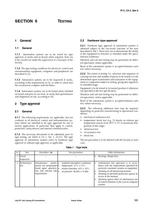
BV船级社型式认可试验标准
of control elements in the case of computer systems
July 2011 with January 2012 amendments
standard atmosphere conditions temperature: 25°C ± 10°C relative humidity: 60% ± 30% air pressure: 96 KPa ± 10 KPa
Other information
• drawings, design data
2-30 Test Db
Humidity: 95%
Duration: 2 cycles (12 + 12 hours)
• measurement of insulation resistance before test
ripple voltage from the charging
device
• +20% to –25% for equipment not
connected to the battery during
charging
4c Pneumatic and
−
Pressure: ± 20%
hydraulic
4a Electric A.C. power supply variations
−
COMBINATION
Voltage variation Frequency varia-
permanent
tion permanent
- 1、下载文档前请自行甄别文档内容的完整性,平台不提供额外的编辑、内容补充、找答案等附加服务。
- 2、"仅部分预览"的文档,不可在线预览部分如存在完整性等问题,可反馈申请退款(可完整预览的文档不适用该条件!)。
- 3、如文档侵犯您的权益,请联系客服反馈,我们会尽快为您处理(人工客服工作时间:9:00-18:30)。
NR 216Chapter 5WELDINGS ECTION1G ENERAL R EQUIREMENTSS ECTION2A PPROVAL OF W ELDING C ONSUMABLESS ECTION3A PPROVAL OF O VER W ELDABLE S HOP P RIMERSS ECTION4A PPROVAL OF W ELDING P ROCEDURESS ECTION5A PPROVAL OF CO2 L ASER W ELDING P ROCEDURESNR 216, Ch 5, Sec 1 SECTION 1G ENERAL R EQUIREMENTS1Scope1.1General1.1.1 This Section specifies the general requirements for fabrication by welding, and the other Sections of the Chap-ter concern the requirements for approval of welding con-sumables ( Sec 2), over weldable shop primers ( Sec 3) and welding procedures ( Sec 4 and Sec 5).1.1.2 The requirements are essentially intended for the welding of weldable steels and aluminium alloy grades cov-ered by the applicable Articles of these Rules.1.1.3 Different materials, applications and procedures, as well as other standards and specifications, may be consid-ered by the Society on a case-by-case basis.2Fabrication by welding2.1General2.1.1 Fabrication by welding is to be carried out in compli-ance with the applicable Society Rules and according to normal good practice, general or specific to the individual processes, to the Surveyor’s satisfaction; in particular the conditions stated at the time of approval and authorisation for the use of individual processes are to be complied with. The welded structures, the relevant details and the size of welds are to comply with the applicable requirements; any other requirements indicated on the approved plans or specified during survey of construction are also to be com-plied with.2.2Approval2.2.1 PlansThe constructional plans are to be submitted for approval when required by the Rules or in individual cases and are to contain the necessary data relevant to the fabrication by welding of the structures and items represented. In particu-lar, material types, welding details, welding processes and weld size are to be indicated; any details not represented in the plans are, in any case, to comply with the applicable requirements.2.2.2 Welding procedures and consumables Welding to be used in hull construction, machinery, pres-sure systems and equipment subject to the inspection of the Society, is to be carried out with approved welding consum-ables and in accordance with approved welding proce-dures. 2.2.3 Welders and welding operatorsWelders for manual welding and for semiautomatic welding processes are to be properly trained and are to be certified by the Society, as required in the individual applications, unless otherwise agreed.Welders are to be certified according to the procedures given in the document NR476 “Approval testing of weld-ers”, except for offshore applications where the Society’s Rule Note “Construction survey of steel structures of off-shore units and installations” referenced NR426 DTO R00 E dated May 1992 is to be used.The certification is to be in due course of validity. Personnel manning the automatic welding machines are to be competent and sufficiently trained.2.2.4 Welding supervisionWelders are to be supervised and assisted, in the course of the welding operation, by an adequate number of compe-tent supervisors, such as to ensure efficient control of the welding production.Certification of the welding inspectors is not compulsory and is left to the discretion of the Manufacturer, except in particular cases where it may be required by the Society. 2.2.5 NDT operatorsNon-destructive tests are to be carried out by qualified per-sonnel certified by the Society or by recognised bodies in compliance with appropriate standards.The qualifications are to be appropriate to the particular application.2.3Welding procedures2.3.1 Approval of consumablesConsumables are to be approved in accordance with the provisions of Sec 2.Requirements for approval of welding procedures, where non-approved welding consumables are allowed to be used, are given in Sec 4.2.3.2 Choice of consumablesRequirements regarding the use of the various grades of approved consumables are indicated in the parts of the Rules concerning the application or at the time of plan approval.In the case of consumables approved for Mo and Cr-Mo weldable steels, the choice of the grade of the consumables is to be made such that the nominal chemical composition of the deposited metal corresponds to that of the base mate-rial; where electrodes are used, they are to be of the basic covered low hydrogen type.NR 216, Ch 5, Sec 1In the case of consumables approved for C, C-Mn and Ni ferritic steels intended for low temperature service, the choice of the grade of consumable is to be made such that the strength of the weld metal is appropriate to the base metal to be welded and the temperature at which the con-sumables satisfy the required impact strength properties is as required in the individual applications; where electrodes are used, they are to be of the basic covered low hydrogen type.In the case of consumables approved for welding stainless steels, the selection of consumables and base metals which can be welded is indicated in Sec 4, [4].In the case of consumables approved for welding alumin-ium alloys, the selection is to be made on the basis of corro-sion resistance and strength as indicated in Sec 4, [6].2.3.3 Manual welding processesManual welding processes using covered electrodes with diameter within the approved range and employing welding techniques according to normal welding practice are con-sidered as ordinary welding processes and, in general, the use of an approved electrode substitutes for qualification tests of the welding procedure.Approval of the welding procedure is, as a rule, required for electrodes for welding quenched and tempered steels and for specific applications such as those relevant to ships intended to carry liquefied gases, in which case the require-ments of the relevant part of the Rules apply.2.3.4 Special welding processesSpecial welding processes are intended to mean those where the heat input from the arc is such as to melt a con-siderable amount of base material and, in any case, those which achieve automatic or semiautomatic welding, in par-ticular:a)processes employing electrodes provided with specialcoatings suitable to obtain a deep penetrationb)automatic or semiautomatic processes employing tubu-lar wires filled with desoxidants and additives with or without shielding gas, or bare wire with shielding gas, including electro-gas and electro-slag processesc)automatic or semiautomatic submerged-arc processes. The welding procedure specifications involving these spe-cial welding processes are to be preliminarily approved for individual users.The special welding processes are to be used within the limits of their approval and in accordance with the condi-tions of use for which the individual Manufacturers have been authorised.2.4Type of joints, edge preparations andsize2.4.1 GeneralThe types of joints and the edge preparations are to be appropriate to the welding processes adopted, to the partic-ular structures and to the stresses to which they are sub-jected, to the satisfaction of the Society.Size and design are to be in accordance with requirements given in the Rules relevant to the applications, approved plans, and specific provisions stipulated for hulls and for pressure systems and machinery.2.5Welding execution and control2.5.1 Edge preparation, surface conditions, assembly pre-and post- weld heating, welding sequences and inspections of the welded structures are to be in accordance with good practice and, where applicable, are to comply with the requirements given in the Rules relevant to the applications.NR 216, Ch 5, Sec 2 SECTION 2A PPROVAL OF W ELDING C ONSUMABLES1General1.1Scope1.1.1 The requirements of this Section apply to the approval and periodical control tests of consumables for welding carbon and carbon manganese steels, high strength quenched and tempered steels, chromium and chromium-molybdenum steels, nickel steels for low temperature appli-cations, austenitic and austenitic-ferritic stainless steels, and aluminium alloys.This Article specifies the requirements common to all the above-mentioned welding consumables, while the appro-priate specific requirements are indicated in Articles [2] to [14].The following categories of welding consumables are con-sidered:•covered electrodes for manual and gravity welding •wire/flux combinations for submerged arc welding •solid wire/gas combinations for continuous wire arc welding•flux cored wires for continuous wire arc welding with or without shielding gas•consumables for electrogas and electroslag welding. 1.2Grading and designation1.2.1 GeneralConsumables are classified depending on the mechanical and chemical properties of the filler metal; different grades or type of consumables may be considered for specific applications or materials on a case-by-case basis.1.2.2 Consumables for C and C-Mn steels and for Q-T steelsWelding consumables intended for welding C and C-Mn steels are divided into groups related to the strength level (minimum specified yield strength) of the steel; each group is subdivided into grades depending on the impact test tem-peratures, as indicated in Tab 1.1.2.3 Consumables for Mo and Cr- Mo steels Consumables intended for welding Mo and Cr-Mo steels are designated by a symbol indicating the nominal Mo and Cr percentage content of the deposited weld metal, as follows:a)M for Mo = 0,5b)C1M for Cr =1,25 and Mo = 0,5c)C2M1 for Cr = 2,25 and Mo = 11.2.4 Consumables for Ni steels for low temperatureapplicationsConsumables intended for welding nickel steels are desig-nated by a symbol indicating the type of nickel steel for which the consumables are intended, as follows:a)N15 for steels with Ni = 1,30 - 1,70 (%)b)N35 for steels with Ni = 3,25 - 3,75 (%)c)N50 for steels with Ni = 4,75 - 5,25 (%)d)N90 for steels with Ni = 8,50 - 10 (%)1.2.5 Consumables for austenitic and austenitic-ferritic (duplex) stainless steels Consumables intended for welding austenitic steels are des-ignated by a symbol corresponding to the AWS designation of the weld deposit, as follows: 308, 308L, 316, 316L, 316LN, 317, 317L, 309L, 309, 309Mo, 310, 310Mo, 347. Consumables intended for welding austenitic-ferritic steels are designated by a symbol indicating the nominal percent-age content of Cr and Ni in the deposited metal (e.g. 2205 means 22% Cr and 5% Ni).Table 1 : Consumable grades for C-Mn steelsWeld metal strength levelConsumable grades based on impact test temperature at (°C)+ 200− 20− 40− 60Normal strength1234−Higher strength (1)•≥ 315, < 360 N/mm2•≥ 360, < 400 N/mm21Y (2)2Y2Y403Y3Y404Y4Y405Y5Y40Extra high strength (1)3Y42, 3Y46, 3Y50,3Y55, 3Y62, 3Y694Y42, 4Y46, 4Y50,4Y55, 4Y62, 4Y695Y42, 5Y46, 5Y50,5Y55, 5Y62, 5Y69(1) The symbol Y, which indicates the high strength groups is followed, for steels having the minimum specified yield strengthequal to or higher than 355N/mm2, by a number related to the minimum specified yield strength value of the weld metal (e.g.42 for a minimum yield strength of 420 N/mm2).(2) Grade not applicable to covered electrodes.NR 216, Ch 5, Sec 21.2.6 Consumables for aluminium alloys Consumables intended for welding aluminium alloys are designated by the initial letter R or W for rod or wire prod-ucts, respectively, and by the letters A, B, C, D depending on the alloy type and strength level used for the approval tests.1.2.7 Additional symbolsFurther symbols may be added, as appropriate, as a prefix or suffix to the grade as indicated in the following :a)Prefix S or SA for semiautomatic welding processb)Prefix A for automatic welding processc)Prefix AV for electrogas or electroslag welding processd)Suffix T, M, TM, U for automatic process with two run(T), multi-run (M), both (TM) or one-side (U) welding techniquese)Suffix H or H15, HH or H10, HHH or H5 for controlledhydrogen content of weld metal as per Tab 8f)Suffix D when mechanical properties on weld metalhave also been verified in the stress relieved condition 1.3Approval procedure1.3.1 Request for approvalThe request for approval is to be submitted to the Society by the Manufacturer, together with the specific information indicated in the Articles relevant to the various consum-ables.1.3.2 Quality of manufacturingThe Manufacturer’s plant, method of production and quality control of welding consumables are to be such as to ensure reasonable uniformity in manufacture.The Manufacturer is to ascertain this uniformity by means of analysis and systematic testing on each production batch. In general, the consumables are to maintain the specified characteristics for a period of time of at least six months after the date of delivery, when properly stored in a dry atmosphere and kept in the original packaging.The consumables are to be supplied so packaged as to ensure compliance with the above requirement; the pack-aging is to be sufficiently strong to resist the usual transpor-tation and handling operations.The Manufacturer is to stamp on each container or bag, as applicable, the markings which are necessary to trace back each production.1.3.3 Approval testsThe welding consumables are approved subject to a satis-factory inspection of the Manufacturer’s works by the Sur-veyor and to satisfactory results of approval tests.The approval tests required are to be performed on samples of consumables representative of the production. Sampling procedures are to be agreed with the Surveyor. In general, the approval tests consist of the following checks:a)check of the operational characteristics of the consum-able and its ability to produce substantially sound welds b)check of the mechanical properties of the depositedmetal and welded joints and of the chemical composi-tion of the deposited metalc)check of the hydrogen contents, where requiredd)check, at the request of the interested parties, of free-dom from hot cracks, under specific test conditions. Welding and inspection of the test samples and mechanical tests are to be carried out in the presence of the Surveyor. The tests are to be carried out in laboratories and test rooms recognised by the Society.Unless otherwise specified, test specimens and procedures are to be in accordance with the applicable Society require-ments or standards recognised by the Society.1.3.4 CertificationUpon satisfactory completion of the approval tests, a certifi-cate of approval, stating the grade under which the consum-able has been approved and the terms of validity of the approval, is issued by the Society to the Manufacturer.The approved welding consumables and relevant grades are entered in the special lists of consumables approved by the Society.1.3.5 Annual inspections and testsThe workshops where approved materials are manufactured are subject to annual inspections by the Surveyor.During the inspection, samples of the approved consum-ables are selected by the Surveyor and subjected to the tests detailed in the Articles relevant to the various products. These tests are to be repeated annually so as to provide an average of at least one test per year.At the Society’s discretion, the consumables to be used in the above tests may be obtained, instead of from the Manu-facturer as stated above, from users or dealers; the consum-ables are to be recently produced (in general less than 6 months).Alternative procedures based on quality control and quality assurance systems may be considered and accepted subject to special approval by the Society, which will state the rele-vant acceptance conditions on a case-by-case basis.1.3.6 Manufacturer’s responsibilitiesAfter the approval has been obtained, and irrespective of the periodical tests carried out by the Society, the Manufac-turer is fully responsible for the quality of the finished prod-uct and compliance with the specified requirements, as verified in the approval and periodical control tests.The Manufacturer is to keep up-to-date records of the man-ufacture of the approved consumables, including details of the history of the single productions and results of associ-ated tests. The Society is to have free access to these records at all times.The Manufacturer is responsible for reporting to the Society any major modifications introduced in the production pro-cedure subsequent to its approval.Full compliance on the part of the Manufacturer with all the requirements stated by the Society in connection with the approval of consumables is an essential condition for grant-ing and renewing such approval.NR 216, Ch 5, Sec 21.3.7 Firms with several workshops or dealers When consumables of the same brand are manufactured in different workshops belonging to the same Manufacturer, the complete series of tests is generally performed in one workshop only. In the other workshops, a reduced test pro-gram, as deemed appropriate in each case, is permitted if the Manufacturer certifies that the material used and the fabrication process are identical to those used in the main works.The same applies to the approval and control tests of con-sumables already approved for one Manufacturer, when the consumables are transferred to another company for sale under a different brand name under the conditions specified by the Society.1.3.8 Changes in gradingChanges in grading of welding consumables are to be con-sidered only at the Manufacturer’s request, in general at the time of annual testing. For upgrading, tests from butt weld assemblies are generally required as a minimum in addition to normal annual tests, as specified here below.F or upgrading referring to impact properties, Charpy V-notch impact tests are to be performed at the upgrade tem-perature on the respective butt weld assemblies required for approval.F or upgrading referring to higher strength steels, all butt weld tests required for the approval are to be effected using higher strength steel as parent metal.For upgrading referring to hydrogen content, tests according to [2.5] are to be carried out as appropriate. Downgrading or withdrawal of the approval occurs when the prescribed tests and re-tests fail to meet the require-ments.1.3.9 Additional testsThe Society may, in some specific cases, request additional tests or requirements as deemed necessary.1.4Preparation and welding of test assem-blies1.4.1 Base materialThe base material used for the test assemblies is to be of the steel grade appropriate to the consumable grade as speci-fied in the various Articles.For the preparation of all weld metal test assemblies, any grade of structural steel may be used. When the chemical composition of welded metal is substantially different from the base material, an overlay of side walls and backing strip may be carried out, as deemed necessary.For the preparation of butt welded assemblies, steel grades are to be chosen depending on the grade of consumables. When a welded joint is performed, the edges of the plates are to be bevelled either by mechanical machining or by oxygen cutting; in the latter case, a descaling of the bev-elled edges is necessary. 1.4.2 Welding conditions and type of current Welding conditions used, such as amperage, voltage, travel speed etc., are to be within the range recommended by the Manufacturer for normal good welding practice.Where it is stated that a filler metal is suitable for both alter-nating current (a.c.) and direct current (d.c.), alternating current is to be used for welding the test assemblies for mechanical tests. When samples for checking the operating characteristics are required, both types of current are gener-ally to be used. When samples for hot cracking tests are required, direct current is to be used.Direct current is identified in the approval documentation with the symbols:•CC+ or DCEP for positive electrode•CC− or DCEN for negative electrode.1.4.3 Post-weld heat treatmentPost-weld heat treatment of the welded assemblies is not allowed where the consumables are to be approved for the as welded condition only.1.5Mechanical tests1.5.1 GeneralThe test specimens for mechanical tests are to be taken from the welded assemblies as indicated in the various Articles; specimen preparation and test results are to comply with the requirements from [1.5.2] to [1.5.6].The requirements relevant to the calibration of the equip-ment, preparation of test specimens and testing procedure, detailed in Ch 1, Sec 2, are also to be complied with, as appropriate.1.5.2 Tensile testsRound test specimens for longitudinal tensile tests and flat test specimens for transverse tensile tests are to be taken as described below:a)round specimen:The longitudinal axis is to coincide with the centre of the weld and mid-thickness of the weld in the all weld metal assemblies and second run in the two run welded assemblies. The specimen is to be in accordance with Ch 1, Sec 2, [2.1.10]; the specimen may be heated to a temperature not exceeding 250°C for a period not exceeding 16 hours, for hydrogen removal prior to test-ing.The yield stress, tensile strength and elongation are to be determined and are to comply with the requirements specified for the various consumables; the reduction of area is to be determined and reported for information.b)flat tensile specimen:The test specimen is to be in accordance with Ch 1, Sec 2, [2.1.11].The tensile strength is to be determined together with the fracture position and is to comply with the require-ments specified for the various consumables.NR 216, Ch 5, Sec 21.5.3 Transverse bend testsFace and root bend test specimens having 30 mm width and full plate thickness are to be machined transverse to the welded joint. The upper and lower surfaces of the weld are to be filed, ground or machined flush with the surface of the plate and the corners in tension rounded to a radius not exceeding 2 mm.Two bend specimens are required; one specimen is to be tested with the face of the weld in tension and the other with the root of the weld in tension.If the plate thickness exceeds 25 mm, it may be reduced to this size by machining on the compression side of the test specimen.Alternatively, two side bend specimens may be taken in lieu of root and face bend specimens; side bend specimens may also be required in addition to or in lieu of root and face bend specimens for specific applications [1.5.4].Bend test specimens are to be bent without fracture or cracks through an angle of 120°, unless a different angle is specified over a former having diameter as indicated in the various Articles; however superficial cracks or open defects not exceeding 3 mm may be disregarded.1.5.4 Side bend testsSide bend test specimens, having full plate thickness and width 10 mm, are generally required in addition to the root and bend tests for the approval of wire/gas combinations, and are required in lieu of the root and bend tests for elec-trogas or electroslag assemblies.1.5.5 Longitudinal bend testsWhen longitudinal face or root bend tests are required, test specimens in accordance with an appropriate standard are accepted.1.5.6 Impact testsCharpy V-notch impact specimens are to be cut with their longitudinal axis transverse to the weld joint and positioned as follows:a)for deposited metal and butt weld test assemblies withmulti-run technique: at mid-thickness of the weldb)for two run welded test assemblies: on the second runside, 2mm below the surfacec)for electroslag and electrogas welded test assemblies: 2mm below the surfaced)for one side automatic welding processes: 2 mm belowthe face side and 2 mm below the root side of the test assemblies; for thicknesses ≥ 30 mm, specimens at mid-thickness are also to be taken.The notch is to be cut in the face of the specimen perpen-dicular to the surface of the plate and to be positioned in the centre of the weld. For electrogas and electroslag weld-ing, an additional set with the notch at 2 mm from the fusion line in the weld metal is to be taken.A set of three specimens is to be prepared and tested. The average impact energy is to comply with the values speci-fied for the various consumables and only one individual value may be lower than the average required, provided it is not lower than 70% of it.1.6Test samples for checking the chemicalcomposition of deposited weld metal1.6.1 For some products (see [11], [12], [13]), the chemical composition of weld metal deposited with electrodes is required to be verified on samples welded for this purpose.1.6.2 The test samples consist of a test plate of the speci-fied steel having minimum sides 80x80 mm2 and 15mm thickness.On the above test plate, whose surface is to be cleaned by grinding to remove any trace of oxide, grease and paint, a weld pad is deposited in layers by welding in the flat posi-tion, each layer being formed by flanked beads. The mini-mum dimensions of the pad are to be as indicated in Tab 2.Table 2 : Pad dimensionsThe width of each bead of each layer is to be 1,5 to 2,5 times the diameter of the electrode. It is recommended that each layer should be deposited in a direction perpendicular to the previous one.The current adopted for welding the test samples is to be within the range recommended by the Manufacturer; in the case of electrodes for use both with a.c. and d.c. current, the welding is to be carried out with alternating current. After each layer has been deposited, the pad may be cooled to room temperature by immersion in water for 30 seconds. The surface of each layer is to be free from slag inclusions and blow holes.1.6.3 After the welding is completed, the top surface of the pad is to be removed by mechanical means and discarded. Shavings sufficient for checking the chemical composition are then to be taken in such a manner that no metal is removed closer to the surface of the base plate than the dis-tance indicated in Tab 3.The use of lubricating oils during the mechanical machining for taking out the shavings is to be avoided.Table 3 : Sampling methodDiameter oftested electrode(mm)Minimum lengthand width of thepad (mm)Minimum thicknessof the pad(mm)2,530 x 30133,25 - max.40 x 4016Diameter of testedelectrode (mm)Minimum distance from the base platefor taking out the shavings (mm)2,563,25 - max.8NR 216, Ch 5, Sec 21.7Re-test procedures1.7.1 GeneralWhen for one or more test samples the execution of the weld, the external examination, the radiographic examina-tion or the fracture produce results which are not consid-ered satisfactory in some respects, and when the respective causes may be traced back to the operator or operating con-ditions, the test samples may be allowed to be repeated, in duplicate if deemed necessary, with the same procedure. In other cases, as well as when cracks are detected, the con-sumable will not be approved.The operating conditions for the re-test samples are to be agreed with the Surveyor, as deemed appropriate.For the approval of the consumable, or for the continuation of the testing program, the re-test samples are to produce satisfactory results.1.7.2 Tensile and bend testsWhere the result of a tensile or bend test does not comply with the requirements, duplicate test specimens of the same type are to be prepared from the same sample and satisfac-torily tested. Where insufficient original welded assembly is available, a new assembly is to be prepared using welding consumables of the same batch. If the new assembly is made with the same procedure (in particular the same num-ber of runs) as the original assembly, only the duplicate re-test specimens need to be prepared and tested. Otherwise, all test specimens are to be prepared for re-testing.1.7.3 Charpy V-notch impact testReference is made to Ch 1, Sec 2, [4.4].2Covered electrodes for manual metal arc welding of C and C-Mn steels2.1Scope2.1.1 GeneralThe requirements of this Article apply to covered electrodes for manual metal arc welding of hull structural steels, of the corresponding grades of steel forgings and castings and of comparable steels intended for other structural applications or pressure systems.2.1.2 DesignationElectrodes are divided, for the various strength levels, into the following grades as defined in [1.2.2] :a)1, 2, 3, 4 for normal strength gradesb)2Y, 3Y, 4Y, 5Y for high strength grades with specifiedminimum yield strength up to 355 N/mm2c)2Y40, 3Y40, 4Y40, 5Y40 for high strength grades withspecified minimum yield strength up to 390 N/mm2. Depending on the hydrogen content of the weld metal, the symbol H15 or H, H10 or HH, H5 or HHH is added to the grade mark as in [1.2.7].The symbols H15, H10, H5 indicate the hydrogen content determined with the mercury method.2.1.3 Information and documentation to besubmittedThe following information and supporting documentation, as appropriate, are generally to be submitted together with the request for approval:a)trade name of the electrodeb)range of diameters and other significant dimensionsc)type of coveringd)grades for which the application is made, includingadditional symbolse)typical chemical composition of the deposited metalf)weld metal recovery (efficiency) according to ISO 2401g)welding technique and type of currenth)proposed range of application and operating character-isticsi)marking and packingj)Manufacturer’s workshop, manufacturing facilities, manufacturing and treatment cycles, methods and pro-cedures of Manufacturer’s quality controlsk)instructions for usel)previous approvals granted to the electrodes with the necessary references.2.2Approval tests2.2.1 GeneralThe approval tests specified in [1.3.3] are to be performed as indicated in [2.3] to [2.7] and summarised in Tab 4 and Tab 5.2.3Tests for checking the operating charac-teristics2.3.1 GeneralThe tests indicated in Tab 4 are required to be performed, at the discretion of the Society, depending on the application and information submitted under [2.1.3].The butt-joint tests of pipes are to be performed, in the spec-ified position, only for electrodes which are considered as suitable for welding pipes.2.3.2 Tee fillet jointThese test samples are required to verify that the electrode concerned, under the actual operational conditions and in the various welding positions for which the approval is requested, is capable of producing a sufficient weld pene-tration and a substantially sound weld.The Tee-joint sample is to be welded with a single fillet, on two plates arranged and having the dimensions as shown in Fig 1.For electrodes having diameter greater than 6 mm (5 mm, in the case of high efficiency electrodes), the test sample is to be 500 mm long and its plates 20 mm thick.The vertical plate is to be perpendicular to the horizontal plate and a proper contact is to be obtained between the facing surfaces.。