WHOLER监听音箱说明书
[教材]PEAVEYVYPYR15音箱中文使用说明书
![[教材]PEAVEYVYPYR15音箱中文使用说明书](https://img.taocdn.com/s3/m/a3af5ad54128915f804d2b160b4e767f5acf80fc.png)
PEAVEY VYPYR 15音箱中文使用说明书刚刚收到vypyr15音箱,简单测试了一下,感觉这款音箱尤其比较适合金属,可惜带的全是外文说明书,为了让买到这款音箱的朋友尽快学会使用,本人根据实际操作做了一个简单的中文操作说明,其实这款音箱的操作很容易入手,并不复杂,这个简单的说明书送给不知如何使用的朋友,错误之处请大家修改补充。
随音箱附带一个中文的“重要的安全说明”,请使用前仔细阅读。
归纳为一句话:音箱注意不要靠近水、火,放置在通风处,注意电源安全可靠,不使用时请拔掉电源及连线。
0-input吉他输入插口,吉他线插入音箱的地方。
1-stompboxes单块选择,vypyr 15不适用。
2-amp音箱模拟选择,旋转这个按钮来选择你想要的音箱类型,同时对应的指示灯亮。
按下去该按钮在音箱的清音和失真通道切换。
如果灯是红的表示在失真通道,如果灯是绿的表示在清音通道。
按下去并保持2秒则进入调音模式,按钮3显示音的高低,如果绿灯在12点钟右侧则需调低,在左侧需调高,当全部灯亮时说明音高标准。
3-effects各种效果选择,按下按钮进入编辑模式,同时编辑指标灯亮(edit mode灯)。
4-pregain前级放大增益,调整失真的大小,在编辑模式下,用来控制效果参数1。
5-low低频调整,在编辑模式下用来控制效果参数2。
6-mid中频调整,在编辑模式下控制延迟的次数。
7-high高频调整,在编辑模式下控制延迟音量,按钮从左到右表示从0到最大值,关到最小时等于无延迟。
8-post gain后级放大增益,控制模拟音箱amp(按钮2)的音量大小,在编辑模式下控制混响数值。
9-Aux输入,可以接mp3、手机、cd机等播放设备。
10-master音箱的主音量。
11-这个vypyr15上没有。
12-power电源开关。
13-presets音色切换按钮,vypyr有12个出厂预置音色。
分A、B、C三组,每组四个音色。
按最左边的按钮bank选组,然后在右边四个音色按钮中选一个音色。
TUBE PREAMP 530 现代汽车音频系统用户手册说明书

professional quality tube sounds in a modern, exceptionally compact 19" rack-mountable package (1 rack space). The two main channels Clean and Lead feature dedicated voicing sections, gain pots and volume controls for precision sound shaping and fine-tuning. The Gain Lo/Hi switch converts the Clean channel to a Crunch channel and, in the Lead channel, the sound spectrum encompasses everything from Heavy Crunch to Ultra Gain. With a 4-band voicing section featuring two midrange bandwidths and ahandy feature is the Defeat function, which bypasses the preamp and routes the guitar signal directly to the output. This feature enables you to connect two preamps in series and this option enlarges the tonal spectrum. The variable Stereo Line Out and a frequency compensated Line O ut give you a wide range of application options, for instance you can patch the preamp signal directly to a mixing console or recording devicewhich is equipped with an impressive array of high-tech features that deliver a wide range of devastating sounds, come highly recommended. The integrated 2 x 1, 5 Watt stereo poweramp is suitable for three different applications:1, practicing with stereo headphones,2. practising with hi-fi stereo speakers, and3, practicing with a conventional guitar speaker cabinet.This preamp is defined by the effort and materials that went into it: intelligent design features, superior craftsmanship, impeccable finishing and quality components. However keep in mind, that a few precautions will radically extend tube life (see handling and care guidness).The entire-Team would like to thank you for your faith in ourproduct; we hope you derive a great deal of joy and satisfaction fromPLEASE NOTE: Read the O perator's Manual carefully and thoroughly, especially the Handling and Care section as well as the guidelines in bold-face type. Avoid operating errors and potential damage to the preamp by heeding the guidelines and cautionary remarks in this manual. The footnotes also cover a few convenient pointers and interesting tips on several functions. These are listed on side 3 of the manual.Gain settings depend on what type of pickups are installed in your guitar. The recommended setting for humbuckers or active pickups lies between the 10 and 1 o ’clock positions and 12 to 3 o ’clock for single coils for a pure clean response.For a crisp glassy tone, set the Bright switch to the On position. This setting boosts the treble response of muddy pickups.To get an idea of this preamp's capabilities in the Clean-Mode, we suggest you set thetone control pots Bass (5), Middle (6) and Treble (7) to the 12 o'clock position.To get Crunch or heavy Rhythm sounds, set this control between the 10 and 1 o ´clock ´s position (depending on the type of pick-up) and leave the Gain Boost (15) pusbuttonin the Off-position. All functions that can be accessed via footswitch can also be switched via the ENGL MIDI Switcher Z- 11. Simply connect the two 1/4" stereo jacks (22) and (23) to the stereo inputs of the Switcher via two cables equipped with 1/4" stereo plugs. You can control switching functions via the buttons on the Switcher. The respective functions (e, g. Lead, Hi -Gain,Contour active, Defeat off) are saved to the desired MIDI program locations. The ENGL MIDI Footswitch Z-12 is ideal for activating MIDI programs. When used in conjunction with the ENGL MIDI Switcher Z-11, this durable footswitch does not require a separateAC power pack. The requisite power is routed via the MIDI cable.To get an idea of this preamp's Lead sounds, we suggest you set the tone control pots Bass (9), Lo Mid (10), Hi Mid (11) and Treble (12) to the 12 o'clock position. The Treble control is important when operating the preamp in combination with a poweramp that does not feature a Presence control: Set the Treble pot between the 7 and 12 o ´clocksposition it suppresses the gritty upper frequencies. The integrated miniature stereo poweramp delivers maximum output of 2 x 1. 5 Watts at 4 ohms. However, you can connect diverse systems with impedances of 4, 8 and 16 ohms as well as headphones with 200 ohms. To the achieve the desired audio result, it is essential that the Selector switch (24) located on the rear panel is set to the proper position. The volume level of the poweramp is determined by the volume level settings for the two channels and the setting of the LINE LEVEL control (29). If the LINE LEVEL pot is turned up fairly high, then the setting for the two volume controls (7) and (14) must be reduced substantially so that the poweramp is not saturated!PLEASE ENSURE YOU HEED THE FOLLOWING: If you are using the amp to drive just one speaker cabinet, connect only one stereo channel via a 1/4" stereo plug. A mono 1/4" plug will short-circuit the poweramp's second channel. If you operate the amp under these conditions at high volumes for a longer period of time, this may destroythe amp or other components!The LINE outputs (25) and (26) provide signals that emulate the response of a 412 guitar cabinet, The signal level is nominally identical to the level at the LINE outputs (27) and (28).However in practice, the level deviates slightly due to frequency compensation. When the preamp is active, the output level of the LINE outputs depends on the following factors:the input level (Gain), the Volume control settings for the respective channels, and in some measure, the voicing section control settings. This is why we recommend that you dial in the desired sound via the front panel control features, set a desired FX level (if you have connected a processor) and then use the LINE LEVEL pot (29) to dial in a suitable level.The following is another conceivable practical application: Patch the outputs (27) and (28) to a stereo poweramp (e.g. ENGL 830/50) to drive two cabinets (e.g. ENGL 412G or S)and the two frequency compensated LINE outputs to the PA mixing console. The emulated 412 signal can be used for the FOH sytem so you do not have to mic your guitar cabinets.The filter stages, integrated LINE amp and the headphones amp can also be used for external application, depending on how you route the signals. Use the two FX LOOP RETURN jacks (30) and (31) as signal inputs. The preamp signal is interrupted when a1/4" jack is inserted. (refer to the Signal Routing Plan).BASSBottom end voicing control for theLead Channel.LO MIDLo Mid-range voicing control (at 500 Hz)for the Lead Channel.LEAD GAINGain control for the Lead channel, controls theamount of distortion in the Lead mode.CAUTION: Extremely high gain and volumelevels in the Lead mode can produce strongfeedback. Avoid feedback squeals, they leadto hearing loss and damaged speakers!TREBLEUpper range voicing control for theClean Channel.7CLEAN VOLUMEVolume control for the Clean channel.BASSBottom end voicing control for theClean Channel.MIDDLEMid-range voicing control for theClean Channel.BRIGHTAlters the EQ by boosting the upper treblerange; (above 2 kHz).Front1INPUTUnbalanced 1/4" (main) input jack.CLEAN GAINHI MIDHi Mid-range voicing control (above 1 kHz)for the Lead Channel.TREBLEUpper range voicing control for theLead Channel.CONTOURPress this button to alter the mid-EQ. When thebutton is pressed, mids between 300 & 500 Hzand mids between 1 & 2 kHz are boostedslightly; the red LED indicates Contour active.This function can also be activated via afootswitch connected to jack (23). Once afootpedal is connected, the channel selectorpushbutton is deactivated.LEAD VOLUMEVolume control for the Lead channel.14GAIN LO / HIThis button increases the gain levels for bothchannels. When you activate it, the Cleanchannel responds more like a Crunch channel,and the Lead channel delivers a hi-gain leadsound. You can also activate this function viafootswitch (Jack 22), the Gain Boost pushbuttonis then no longer functional. The LEDilluminates to indicate Hi-Gain mode is active.CLEAN / LEADChannel selector pushbutton for Clean andLead modes, red LED indicate Lead mode;This function can also be activated via afootswitch connected to jack 22. Once a foot-pedal is connected, the channel selector push-button is deactivated.PREAMP DEFEATThis feature bypasses the preamp when thebutton is depressed. In this case the guitarsignal is routed to the Instrument Outputjack (32) .You can also activate this function viafootswitch (at Jack 23), the Preamp Defeatpushbutton is then no longer functional.The LED above the button illuminates toindicate the preamp is bypassed.POWERAC power on/off.19STEREO HEAD PHONES1/4" stereo output designed for stereoheadphones. you can also connecthi-fi speakers or guitar cabinets. When youconnect a conventional guitar cabinet set theselector switch (24) to ,,Routed to GuitarCabinet."CAUTION! Ensure You Heed The Following:Always use a 1/4 stereo plug. If you use amono plug, it may short-circuit and destroythe poweramp!Rear Planel20AC SocketConnect AC cord here.CAUTION: Ensure you use an intact ACcord with an insulated plug only! Beforeyou power the amp up, ensure the voltagevalue printed beside the AC socketcorresponds to the available current.21AC Fuse BoxContains mains fuse (rear chamber) andspare fuse (front chamber).NOTE: Ensure replacement fuses bearidentical ratings (refer to the table)!22FOOTSWITCH:CLEAN/LEAD; GAIN LO/HI1/4" stereo jack for connecting a dualfootswitch (e.g. ENGL Z-11) or a MIDI-switching system (e.g. ENGL Z-11).The following functions can be executed:1.Channel switching Clean - Lead(mono terminal)2.Gain Lo - Hi (stereo terminal).23FOOTSWITCH:PREAMP DEFEAT; CONTOUR1/4" stereo jack for connecting a dualfootswitch (e.g. ENGL Z-11) or a MIDI-switching system (e.g. ENGL Z-11).The following functions can be executed:1.Preamp Defeat / Bypass(mono terminal).2.Contour switching (stereo terminal).24HEADPHONES OUTPUT:A) Routed To Headphones Or HiFi Cab.B) Routed To Guitar Cab.Rear panel selector switch for front panelheadphones jack. Set the switch to the leftposition A) when you connect stereoheadphones or hi-fi speakers and to theright position B) when you connect aguitar cabinet to ensure proper frequencycompensation for the respective systems.FREQUENCY COMPENSATED LINEOUTPUT: RIGHTLine Out for the preamp's right frequencycompensated signal (1/4" unbalanced jack).This signal can be patched directly to amixing console or a recording device.FREQUENCY COMPENSATED LINEOUTPUT: LEFTLine Out for the preamp's left frequencycompensated signal (1/4" unbalanced jack).This signal can be patched directly to amixing console or a recording device.LINE OUTPUT: RIGHTLine Out for the preamp's right channel(1/4" unbalanced jack).This signal can be routed to a powerampor a FX device via a shielded cable.LINE OUTPUT: LEFTLine Out for the preamp's left channel(1/4" unbalanced jack).This signal can be routed to a powerampor a FX device via a shielded cable.LINE LEVELThis control feature determines the level ofthe LINE outputs 25, 26, 27 and 28. Theinstrument output (32) signal can also beamplified to 15 dB if required.29FX LOOP RETURN: RIGHTSignal input right stereo channel for theFX Loop. Connect this input to a signalprocessor’s right output/send jack via ashielded cable with 1/4" plugs.30FX LOOP RETURN: LEFTSignal input left stereo channel for theFX Loop. Connect this input to a signalprocessor’s left output/send jack via ashielded cable with 1/4" plugs.31INSTRUMENT OUTPUTFX LOOP SENDOutput for patching the preamp signal to apoweramp input or the input of a anotherpreamp or signal processor/FX device.Ensure you use a short shielded cable forthis signal circuit.AUXILIARY INPUTSupplentary preamp input. This circuit is routedin series with the input located on the frontpanel and is used for patching the setup to a19" rack. The front panel input has priority. Inother words, when you insert a plug into thefront panel jack (1), the signal routed in via theAux. Input (33) is interrupted.33The INSTRUMENT OUTPUT (32) delivers a signal similar to the one generated by a guitar'spickups when the preamp is active (PREAMP DEFEAT switch Off), i.e. a high-ohm signal at about the same level as a guitar signal. This feature is relevant when you want to establish the same conditions via a bypass circuit (guitar signal to the INSTRUMENT OUTPUT) for further signal processing, for instance by an FX device, another Preamp connected in series or a poweramp.You can connect a signal processor between the INSTRUMENT OUTPUT (32) and the FX LOOP RETURN jacks (30) and (31) or directly between the LINE OUTPUTS (27) and (28) and a stereo poweramp's inputs. There is a substantial difference between these two applications:When you connect the Processor to the FX LOOP, the send signal is identical to the guitar signal when the preamp is in defeat mode and the preamp signal when the defeat mode is off. The send level only is influenced by the settings of the volume controls in this case.The level of the master output signal routed to the LINE outputs can be increased via the LINE LEVEL (29) pot.However, when you connect the Processor between the LINE outputs and the poweramp,the input (Send) signal to the FX device can be increased via the LINE LEVEL (29) pot and you have two Send signals (left, right) available. This option is recommended for low impedance (0 dB)FX devices that are not equipped with a variable input.Technical DataCaution: Replace fuses only with others of the same rating!INSTRUMENT: -10 dB max. 0 dB LINE OUT: -10 dB max.15 dB Output level (0 dB => 1Veff)Tubes:approx.4 kgV1 => ECC83/12AX7 FirstQuality V2 => ECC83/12AX7 selected Dimensions:Weight:19", 1 rack spaces, depth: 260 mm INPUT: -20 dB max. -3 dB Input level(0 dB => 1Veff) 2 x 1,5 Watts at 4 OhmsHeadphones poweramp:Power Consumption: approx. 16 Watts max.Fuses100 & 120 Volts 400 mAM 500 mATAC Mains: external:internal:230 Volts 200 mAM 250 mATM => medium, T => slowchanged!Internal Signal-path:INSTRUMENTHandling and CareProtect the preamp from mechanical knocks (tubes!).Let the preamp cool down before you transport it (approx. 10 minutes).Tubes need about 20 seconds to warm up after you switch the power on.Avoid storing the preamp in damp or dusty rooms, they are hard on jacks, switches and potentiometers.criteria) to avoid microfonic properties, undesireable noise and feedback.W e r e s e r v e t h e r i g h t t o m a k e u n a n n o u n c e d t e c h n i c a l u p g r a d e s !ENGL Ger ätebau GmbH, Germany; Internet: Text, design, grafics and layout by Horst Langer。
惠威有源演艺音箱 ET1000 说明书
(ET1000)HiVi 惠威.美国11630 Goldring Road,Arcadia,CA 91006,USA Tel:+1 626 930 0606 Fax:+1 626 930 0609HiVi 惠威.中国珠海惠威科技有限公司广东省珠海市联港工业区大林山片区东成路南1号电话:0756-******* 传真:0756-*******、6268052客户服务热线:400-090-9199HiVi Acoustics, Inc.因设计变更等原因,所示资料可能与实物不符,恕不另行通知。
in conformity with product itself. We reserve the right of no prior notice before change.惠威有源演艺音箱产品说明书重要安全注意事项和符号说明小心触电,非拥有相关资质的人员请勿擅自开盖维修。
该标记标示危险的带电端子,当将外接电线连接到这种端子时,必须由“受过专业培训的操作人员”进行连接,或使用可进行安全连接的特制引线或电线。
主箱背板回声音量调节旋钮混响音量调节旋钮总音量调节旋钮感谢阁下选购惠威高品质专业音频有源演艺系列产品。
ET系列有源DSP卡拉OK音箱是惠威专业音响全新推出的一款专业有源二分频全频后导向音箱,其中两只低音单元,由锥形纸盆和高密度阻尼泡沫棉折环构成,大大延长单元的使用寿命,四只高音单元,高频清透明亮,提供更广阔的声音范围,拥有性能优越的单元设计。
ET系列卡拉OK音箱功能齐全,APP控制和遥控控制,内置蓝牙、无线话筒和效果器,FM收音、乐器输入等功能和接口。
适用于专业、家庭、会议及院校等多个应用场景,搭配一台点歌机即可完成一整套的KTV系统。
智能化、操控高效,是不可多得的高性能、高稳定性、高可靠性的优质产品。
其声音清晰、透明,音质同Hi-Fi产品媲美。
产品采用了传统的模拟电流和模拟功放电路,听感舒适,人声突出,音乐细腻。
英顿音响使用说明书

英顿音响使用说明书
第一步:打开蓝牙音响。
音响的蓝牙音响只需打开音响电源开关(其他蓝牙音响需要把开关播到标有蓝牙图标方向,直到听到两声“嘟嘟”或有语音提示蓝牙音响已开启),然后蓝牙指示灯呈现闪烁状态,表示蓝牙已经开启,并已经进入可搜索模式。
第二步:蓝牙搜索。
打开手机蓝牙功能,在手机蓝牙设置中设为“所以有可见”,然后点“搜索”查找蓝牙设备,搜到后点击选择蓝牙设备,蓝牙连接,同时蓝牙音响会“嘟”的一声。
第三步:音乐播放。
接下来就可以同步播放手机里的音乐了。
音响产品说明书指导你正确设置和使用音响设备享受高品质音效

音响产品说明书指导你正确设置和使用音响设备享受高品质音效音响产品说明书-指导你正确设置和使用音响设备,享受高品质音效引言:音响设备在现代生活中扮演着重要角色,无论是在家庭娱乐中还是在职业领域中,都能带来高品质的音效体验。
为了让您充分享受音响设备的优势,本说明书将为您提供详细的设置和使用指南。
通过正确设置和使用音响设备,您将能够获得出色的音响效果,并为您的生活增添更多乐趣。
第一部分:设置音响设备1.选择合适的位置在设置音响设备之前,确定一个合适的位置至关重要。
考虑到音响的声场效果,建议将音响放置在房间的中央位置,以获得最佳的音效覆盖范围。
此外,要确保音响设备远离墙壁和其他家具,以减少反射和共振的干扰。
2.连接音频源将音频源(如电视、音乐播放器或电脑)与音响设备连接起来是设置过程中的重要一步。
在连接过程中,请参考音响设备的用户手册,确保正确地插入音频插孔。
一般来说,使用高质量的音频线材能够提供更好的音质传输效果。
3.电源和电源线设置在将音响设备插入电源之前,请确保电源线符合相关的安全标准,并处于良好的使用状态。
此外,应将插头正确地插入电源插座,并确保电源线不被家具或其他物体压迫,以免造成损坏或电线短路。
第二部分:正确使用音响设备1.调整音量和音调当音响设备设置完毕后,您可以开始调整音量和音调以获得最佳的音效效果。
根据个人的喜好和音频源的特点,选择合适的音量大小和音调设置。
请注意,过高的音量可能对您的听力造成损害,因此请谨慎调整。
2.选择适当的音效模式现代音响设备通常提供多种音效模式,如立体声、环绕声等。
根据您的需求和音频源的类型,选择一个适合的音效模式以获得加强的音频效果。
通过合理使用音效模式,您可以在影视观赏或音乐欣赏中体验更加丰富的感官享受。
3.维护和保养音响设备定期进行音响设备的维护和保养,能够延长其使用寿命并保持其良好的音响效果。
请务必定期清洁音响设备的外壳和音频插孔,以避免灰尘的积累。
此外,定期检查电源线和插头的状态,并确保其连接牢固。
T系列全频专业扬声器产品说明书

T4.64寸6单元全频专业扬声器T系列全频专业扬声器系统产品说明书CN UM-T4.6-20090507 v e r A感谢您购买 产品!请仔细阅读本手册,它将帮助你妥善设置并运行您的系统,使其发挥卓越的性能。
并保留这些说明以供日后参照。
警告:为了降低火灾与电击的风险,请不要将产品暴露在雨中或潮湿环境中。
警告:为了降低电击的风险,非专业人士请勿擅自拆卸该系统。
仅供专业人士操作。
等边三角形中的闪电标记,用以警示用户该部件为非绝缘体,系统内部存在着电压危险,电压。
可能足以引起触电。
可能足以引起触电如系统标有带惊叹号的等边三角形,则是为提示用户严格遵守本用户指南中的操作与维护规定。
注意:请勿对系统或附件作擅自的改装。
未经授权擅自改装将造成安全隐患。
警告:燃不得将明火源(如点的蜡烛)放在器材上面。
1. 请先阅读本说明。
2. 保留这些说明以供日后参照。
3. 注意所有警告信息。
4. 遵守各项操作指示。
5. 不要在雨水中或潮湿环境中使用本产品。
6. 不要将产品靠近热源安装,例如暖气管、加热器、火炉或其它能产生热量的装置(包括功放机 )。
7. 不要破坏极性或接地插头的安全性设置。
如果提供的插头不能插入插座,则应当请专业人员更换插座。
8. 保护好电源线和信号线,不要在上面踩踏或拧在一起(尤其是插头插座及穿出机体以外的部分 )。
9. 使用厂商规定及符合当地安全标准的附件。
10.雷电或长时间不使用时请断电以防止损坏产品。
12. 不要让物体或液体落入产品内——它们可能引起火灾或触电。
13. 请注意产品外罩上的相关安全标志。
. 仅与厂商指定或与电器一同售出的推车、架子、三脚架、支架或桌子一起使用。
推动小车/电器时,应谨防翻倒。
11注意事项产品的安装调试须由专业人士操作。
在使用非本厂规定的吊装件时,要保证结构的强度并符合当地的安全规范。
警告:1扬声器及扬声器系统的产品有限保修期为自正式购买日起的3年。
由于用户不合理的应用而导致音圈烧毁或纸盆损坏等故障,不包含于产品保修项目。
朗文音响子woofer MO说明书

Subwoofer MODELXTRPRO102XTRPRO104XTRPRO122XTRPRO124XTRPRO152XTRPRO154OWNER'S MANUALFEATURES1 2 315414135 1211 67 Figure 1Figura 1Abbildung 110 9 81Polypropylene dust cap - moisture and UV resistant.2Oversized NBR (Nitrile-butadiene Rubber) surround for linear controlled long excursion.3Paper cone - moisture and UV resistant.4Custom cast aluminum frame.5Vented Aluminum voice coil former (2.5" voice coil former).68mm steel front plate.7Large 2 stack ceramic magnets.88mm steel back plate/pole piece T yoke assembly.9 1.125" vent. Part of the enhanced voice coil cooling system (forcedconvection).10PVC magnet protector.11High temperature Copper dual 2 ohm or dual 4 ohm voice coil.12Venting in voice coil former. Part of the enhanced voice coil cooling system (forced convection).13Dual Interlaced Conex spider with stitched and looped tinsel leads attached.14Custom terminal blocks.15ABS Trim Ring.2 o h m2 o h m2 o h m2 o h mWIRING CONFIGURATIONSSeries - One Speaker (dual 2 ohm voice coils)One dual 2 ohm voice coil woofer with voice coils in connected in series results in a 4 ohm load to the amplifier.___+Figure 2 Figura 2Abbildung 2++1.Connect the woofer in series by connecting the negative (-) of one terminal to the positive (+) terminal of the other coil.2.Wire the positive (+) terminal of the first coil to the positive (+) terminal on the amplifier. Wire the negative (-) terminal of the second coil to the negative (-)terminal on the amplifier.Parallel—One Speaker (dual 2 ohm voice coils)One dual 2 ohm voice coil woofer with voice coils in parallel results in a 1 ohm load to the amplifier._ __Figure 3+Figura 3 ++Abbildung 31.Connect the speaker in parallel by connecting the two positive (+) terminalstogether and the two negative (-) terminals together.2.Wire the positive (+) terminals of the woofer to the positive (+) terminal on the amplifier. Wire the negative (-) terminals of the woofer to the negative (-)terminal on the amp.4 o h m4 o h mParallel — One Speaker (dual 4 ohm voice coils)One dual 4 ohm voice coil woofer with voice coils in parallel results in a 2 ohm load to the amplifier._ __Figure 4+Figura 4 ++Abbildung 41.Connect the speaker in parallel by connecting the two positive (+) terminalstogether and the two negative (-) terminals together.2.Wire both positive (+) terminals of the woofer to the positive (+) terminal onthe amplifier. Wire both negative (-) terminals of the woofer to the negative (-)terminal on the amplifier.4 o h m4 o h m4 o h m4 o h mParallel - Two Speaker (dual 4 ohm voice coils)Two dual 4 ohm voice coil woofers with voice coils in parallel and the two woofers in parallel results in a 1 ohm load to the amplifier.- -- -++++Figure 5 Figura 5 Abbildung 51.Connect the speaker in parallel by connecting the four positive (+) terminals together and the four negative (-) terminals together.2.Wire the positive (+) terminals of the woofers to the positive (+) terminal onthe amplifier. Wire the negative (-) terminals of the woofers to the negative (-)terminal on the amplifier.2 o h m2 o h mSeries/Parallel - Two Speakers (dual 2 ohm voice coils)Note: Verify and ensure that the woofer wiring is connected as shown with the negative connection from the first woofer coil connected to the positive connection of the second woofer coil.Two dual 2 ohm voice coil woofers with voice coils in series and then parallel the two series woofers results in a 2 ohm load to the amplifier.- -- -+ + ++1.Connect each woofer in series by connecting the negative (-) of the first coil to the positive (+) terminal of the second coil.2.Wire the positive (+) terminal of the first coil on each woofer to the positive (+)terminal on the amplifier. Wire the negative (-) terminal of the second coil on each woofer to the negative (-) terminal on the amplifier.Three dual 4 ohm voice coil woofer with voice coils of each woofer wired in series and then parallel the three woofers for a resulting 2.67 ohm load to the amplifier.-+1. Connect each woofer in series by connecting the negative (-) of the first coil to the positive (+) terminal of the second coil.2. Wire the positive (+) terminal of each woofer’s first coil to the positive (+) terminal on the amplifier. Wire the negative (-) terminal of each woofer’s second coil to the negative (-) terminal on the amplifier.Three dual 2 ohm voice coil woofer with voice coils of each woofer wired in series and then parallel the three woofers for a resulting 1.33 ohm load to the amplifier.-+1. Connect each woofer in series by connecting the negative (-) of the first coil to the positive (+) terminal of the second coil.2. Wire the positive (+) terminal of each woofer’s first coil to the positive (+) terminal on the amplifier. Wire the negative (-) terminal of each woofer’s second coil to the negative (-) terminal on the amplifier.4 o h m4 o h m4 o h m4 o h m4 o h m4 o h mFour dual 4 ohm voice coil woofers should be wired with the voice coils on each woofer in series and then parallel the four woofers for a resulting 2 ohm load to the amplifier.--------+ +++1. Connect each woofer in series by connecting the negative (-) of the first coil to the positive (+) terminal of the second coil.2. Wire the positive (+) terminals of the first coil of each woofer to the positive (+) terminal on the amplifier. Wire the negative (-) terminal of the second coil of each woofer to the negative (-) terminal on the amplifier.2 o h m2 o h m2 o h m2 o h m2 o h m2 o h m2 o h m2 o h mFour dual 2 ohm voice coil woofers should be wired with the voice coils on each woofer in series and then parallel the four woofers for a resulting 1 ohm load to the amplifier-------+ + ++ ++ ++1. Connect each woofer in series by connecting the negative (-) of the first coil to the positive (+) terminal of the second coil.2. Wire the positive (+) terminals of the first coil of each woofer to the positive (+) terminal on the amplifier. Wire the negative (-) terminal of the second coil of each woofer to the negative (-) terminal on the amplifier.2 o h m--++-Figure 11 Figura 11 Abbildung 111. Connect one of the speaker’s voice coils to the first amplifier by connectingthe positive (+) terminal and the negative (-) terminal from the speaker to the respective positive (+) terminal and the negative (-) terminal from the first amplifier.2. Connect the other of the speaker’s voice coils to the second amplifier by connecting the positive (+) terminal and negative (-) terminal from the speaker to the respective positive (+) terminal and the negative (-) terminal from second amplifier.4 o h m--++-Figure 12 Figura 12 Abbildung 121. Connect one of the speaker’s voice coils to the first amplifier by connectingthe positive (+) terminal and the negative (-) terminal from the speaker to the respective positive (+) terminal and the negative (-) terminal from the first amplifier.2. Connect the other of the speaker’s voice coils to the second amplifier by connecting the positive (+) terminal and negative (-) terminal from the speaker to the respective positive (+) terminal and the negative (-) terminal from second amplifier.SPECIFICATIONSModel/Part Number XTRPRO102XTRPRO104XTRPRO122 Thiele/Small ParametersFs (free-air resonance, Hz)33.232.230.5 Vas (equivalent compliance, cu. ft.)0.5070.586 1.198 Vas (equivalent compliance, liters)14.3716.6133.950 Qms (Q, mechanical) 5.42 5.17 6.02 Qes (Q, electrical)0.480.520.62 Qts (total driver Q)0.460.470.56Re (DC resistance, ohms)47.2 4.1Z (nominal impedance, ohms)484Le (inductance, mh) 1.94 2.88 2.06 Efficiency (1W @ 1M, dB)81.382.183.7 Efficiency (2.86 V @ 1M, dB)85.282.887.2 Xmax (one way linear excursion, in.)0.7020.7020.702 Xmax (one way linear excursion, mm)17.82517.82517.825 Pe (continuous power handling, watts rms)500500500 Peak power handling (music, watts) *100010001000 Mms (total moving mass, grams)181.17166.82244.17 Cms (mechanical compliance, mm/N)0.1270.1460.112Bl (motor strength, Tesla-M)17.5821.5817.05Sd (effective radiating area, sq. cm.)283.529283.529463.770 Sd (effective radiating area, sq. m.)0.0280.0280.046 Sd (effective radiating area, sq. in.)43.96443.96471.912 Frequency range (Hz)28 - 50032.1 - 50030.5-500 Energy Bandwidth Product (EBP) **696249 Driver Physical DimensionSpeaker Displacement (cu ft)0.0680.0680.091 Mounting hole diameter (inches/mm)9.61/2449.61/24410.91/277 Mounting depth (inches/mm) 5.86/149 5.86/149 6.45/164 Magnet Weight (Oz)96.0096.0096.00 Basket diameter (inches/mm)10.23/26010.23/26012.28/312 Recommended EnclosuresTypical sealed enclosure (cu. ft.)0.750.75 1.50 Vented enclosure (cu. ft.) ***0.750.75 1.50 Port tuning frequency (Hz)44.0044.0040.00 Port diameter (inside, inches) 3.00 3.00 4.00 Port square equivalent (inches) 2.659 x 2.659 2.659 x 2.659 3.545 x 3.545SPECIFICATIONSModel/Part Number XTRPRO124XTRPRO152XTRPRO154 Thiele/Small ParametersFs (free-air resonance, Hz)32.323.428.7 Vas (equivalent compliance, cu. ft.) 1.256 3.464 3.207 Vas (equivalent compliance, liters)35.59098.13090.860 Qms (Q, mechanical) 5.89 5.49 5.93 Qes (Q, electrical)0.660.670.84 Qts (total driver Q)0.590.610.73Re (DC resistance, ohms)7.1 4.27.2Z (nominal impedance, ohms)848Le (inductance, mh) 2.82 1.96 3.05 Efficiency (1W @ 1M, dB)84.486.385.9 Efficiency (2.86 V @ 1M, dB)85.189.286.9 Xmax (one way linear excursion, in.)0.6800.6800.680 Xmax (one way linear excursion, mm)17.2517.2517.25Pe (continuous power handling, watts rms)500500500 Peak power handling (music, watts) *100010001000 Mms (total moving mass, grams)214.58296.76290.58 Cms (mechanical compliance, mm/N)0.1130.1140.106Bl (motor strength, Tesla-M)21.6216.5721.18Sd (effective radiating area, sq. cm.)471.435779.311779.311 Sd (effective radiating area, sq. m.)0.0470.0780.078 Sd (effective radiating area, sq. in.)73.100120.839120.839 Frequency range (Hz)32.3-50023.4-50028.7-500 Energy Bandwidth Product (EBP) **493534 Driver Physical DimensionSpeaker Displacement (cu ft)0.0910.1430.143 Mounting hole diameter (inches/mm)10.91/27713.85/35213.85/352 Mounting depth (inches/mm) 6.46/1647.48/1907.48/190 Magnet Weight (Oz)96.0096.0096.00 Basket diameter (inches/mm)12.28/31215.27/38815.27/388 Recommended EnclosuresTypical sealed enclosure (cu. ft.) 1.50 2.00 2.00 Vented enclosure (cu. ft.) *** 1.50 3.00 3.00 Port tuning frequency (Hz)40.0036.0036.00 Port diameter (inside, inches) 4.00 4.00 4.00 Port square equivalent (inches) 3.545 x 3.545 3.545 x 3.545 3.545 x 3.545Enclosure Details1. Parameters listed are for conventional applications only, for further help pleasecall Audio Tech Support.2. At least 0.75" MDF (Medium Density Fiberboard) is recommend for any XTRPROenclosure.3. Recommended enclosures are NET box volumes, speaker and port displacementare calculated into the volume of the enclosure, you will not need to add these volumes to calculate GROSS volume for the enclosure.Notes* Due to the high power capabilities and long excursion of the XTRPRO woofers, the Thiele/Small Parameters were calculated and measured using a Klippel analyzer system.** Energy Bandwidth Product (EBP) is determined by the following formula Fs/ Qes=EBP. EBP values of 50 and lower suggest a sealed enclosure is best, 50 to90 means the subwoofers versatile and 90 and above mean vented Enclosure is recommended.*** Subsonic filter should always be used and adjusted specifically for vented box designs.Figure 13Figura 13Abbildung 13XTRPRO102XTRPRO104XTRPRO122XTRPRO124XTRPRO152XTRPRO154 Dimensions inches/mm, Dimensions po/mm, Dimensiones plg./mm, Abmessungen Zoll/mm, Dimensioni pollici/millimetri, Dimensões polegadas/mmA 5.87/149 5.87/149 6.46/164 6.46/1647.49/1907.49/190B 2.84/72 2.84/72 2.84/72 2.84/72 2.84/72 2.84/72C 6.15/156 6.15/156 6.15/156 6.15/156 6.15/156 6.15/156D8.87/2258.87/22510.91/27710.91/27713.87/35213.87/352ENCLOSURE RECOMMENDATIONSEnclosure Details1. External dimensions calculated for 3/4” building material2. Includes speaker displacement3. Volumes given are net tuning volume4. Enclosures include a minimal amount of damping material. Just enough material to line the inside of the enclosure is required.XTRPRO102 & 104 Sealed Enclosure RecommendationsBox Properties— Description —T ype: Closed BoxShape: Prism, Square— Box Parameters —Vb = 0.75 cu.ftV(total) = 0.791 cu.ftQtc = 0.598QL = 7F3 = 50.61 HzFill = noneExternal DimensionsA = 12 in. (305 mm)B = 15.5 in. (394 mm)C = 10.8 in. (274 mm)Internal DimensionsA = 10.5 in. (267 mm)B = 14 in. (356 mm)C = 9.3 in. (236 mm)Wall ThicknessFront = 0.75 in. (19 mm)Side = 0.75 in. (19 mm)T op &BottombFront &BackSides—Box Parts—Box Shape: Square Prism1 T op, 1 Bottom:depth (c) = 10.8 in. (274 mm)width (b) = 15.5 in. (394 mm)thickness = 0.75 in. (19 mm)1 Front, 1 Back:height (a) = 10.5 in. (267 mm)width (d) = 14 in. (356 mm)thickness = 0.75 in. (19 mm)2 Sides: height (a) = 10.5 in. (267 mm)depth (c) = 10.8 in. (274 mm)thickness = 0.75 in. (19 mm)F i gure 14F i gura 14—Driver Mounting—Mounting: Front— Description — Type: Vented BoxShape: Prism, Square— Box Parameters — Vb = 0.75 cu.ft V(total) = 0.841 cu.ft Fb = 44 Hz QL = 7 F3 = 35.24 HzFill =none — Vents —No. of Vents = 1Vent shape = round Vent ends = one flush Dv = 3 in. (76 mm)Lv= 11.19 in. (284 mm)F i gure 15 F i gura 15Abb i ldung 15External DimensionsA = 12 in. (305 mm)B = 15.5 in. (394 mm)C = 11.39 in. (289 mm)Internal DimensionsA = 10.5 in. (267 mm)B = 14 in. (356 mm)C = 9.89 in. (251 mm)Wall ThicknessFront = 0.75 in. (19 mm) Side = 0.75 in. (19 mm)T op &BottombFront & BackhSides—Box Parts—Box Shape: Square Prism 1 T op, 1 Bottom:depth (c) = 11.39 in. (289 mm) width (b) = 15.5 in. (394 mm) thickness = 0.75 in. (19 mm) 1 Front, 1 Back:height (a) = 10.5 in. (267 mm) width (d) = 14 in. (356 mm) thickness = 0.75 in. (19 mm)height (a) = 10.5 in. (267 mm) depth (c) = 11.39 in. (289 mm) thickness = 0.75 in. (19 mm)—Driver Mounting— Mounting: FrontVent Parts 1 Duct:outside diameter (e) = 3.25 in. (83 mm) inside diameter (g) = 3 in. (76 mm) length (h) = 11.19 in. (284 mm)— Description —T ype: Closed BoxShape: Prism, Square— Box Parameters —Vb = 1.5 cu.ftV(total) = 1.55 cu.ftQtc = 0.717QL = 6.886F3 = 43.09 HzFill = noneExternal DimensionsA = 16 in. (406 mm)B = 16 in. (406 mm)C = 14.24 in. (362 mm)Internal DimensionsA = 14.5 in. (368 mm)B = 14.5 in. (368 mm)C = 12.74 in. (324 mm)Wall ThicknessFront = 0.75 in. (19 mm)Side = 0.75 in. (19 mm)T op &BottombFront &BackSides—Box Parts—Box Shape: Square Prism1 T op, 1 Bottom:depth (c) = 14.24 in. (362 mm)width (b) = 16 in. (406 mm)thickness = 0.75 in. (19 mm)1 Front, 1 Back:height (a) = 14.5 in. (368 mm)width (d) = 14.5. (368 mm)thickness = 0.75 in. (19 mm)2 Sides:height (a) = 14.5 in. (368 mm)depth (c) = 14.24 in. (362 mm)thickness = 0.75 in. (19 mm)F i gure 16F i gura 16Abb i ldung 16—Driver Mounting—Mounting: Front— Description —Type: Vented BoxShape: Prism, Square— Box Parameters — Vb= 1.5 cu.ftV(total) = 1.637 cu.ftFb = 40 HzQL = 6.886F3 = 32.19 HzFill = none— Vents —No. of Vents = 1Vent shape = roundVent ends = one flushDv = 4 in. (102 mm)Lv = 11.26 in. (286 mm)F i gure 17F i gura 17Abb i ldung 17External DimensionsA = 13.5 in. (343 mm)B = 18.5 in. (470 mm)C = 15.36 in. (390 mm)Internal DimensionsA = 12 in. (305 mm)B = 17 in. (432 mm)C = 13.86 in. (352 mm)Wall ThicknessFront = 0.75 in. (19 mm)Side = 0.75 in. (19 mm)T op &BottombFront &BackhSides—Box Parts—Box Shape: Square Prism1 T op, 1 Bottom:depth (c) = 15.36 in. (390 mm)width (b) = 18.5 in. (470 mm)thickness = 0.75 in. (19 mm)1 Front, 1 Back:height (a) = 12 in. (305 mm)width (d) = 17 in. (432 mm)thickness = 0.75 in. (19 mm)height (a) = 12 in. (305 mm)depth (c) = 15.36 in. (390 mm)thickness = 0.75 in. (19 mm)—Driver Mounting—Mounting: FrontVent Parts1 Duct:outside diameter (e) = 4.25 in. (108 mm)inside diameter (g) = 4 in. (102 mm)length (h) = 11.26 in. (286 mm)— Description —Type: Closed BoxShape: Prism, Square— Box Parameters — Vb= 2 cu.ftV(total) = 2.078 cu.ftQtc = 0.963QL = 5.281F3 = 37.55 HzFill = noneExternal DimensionsA = 17.5 in. (445 mm)B = 17.5 in. (445 mm)C = 15.52 in. (394 mm)Internal DimensionsA = 16 in. (406 mm)B = 16 in. (406 mm)C = 14.02 in. (356 mm)Wall ThicknessFront = 0.75 in. (19 mm)Side = 0.75 in. . (19 mm)Top &BottombFront &BackSides—Box Parts—Box Shape: Square Prism1 Top, 1 Bottom:depth (c) = 15.52 in. (394 mm)width (b) = 17.5 in. (445 mm)thickness = 0.75 in. (19 mm)1 Front, 1 Back:height (a) = 16 in. (406 mm)width (d) = 16 in. (406 mm)thickness = 0.75 in. (19 mm)2 Sides:height (a) = 16 in. (406 mm)depth (c) = 15.52 in. (394 mm)thickness = 0.75 in. (19 mm)F i gure 18F i gura 18Abb i ldung 18—Driver Mounting—Mounting: Front1 Duct:outside diameter (e) = 4.25 in. (108 mm)inside diameter (g) = 4 in. (102 mm)length (h) = 5.422 in. (138 mm)XTRPRO152 & 154 Vented Enclosure RecommendationsBox Properties— Description —Type: Vented BoxShape: Prism, Square— Box Parameters — Vb= 3 cu.ftV(total) = 3.116 cu.ftFb = 36 HzQL = 5F3 = 29.7 HzFill = none— Vents —No. of Vents = 1Vent shape = roundVent ends = one flushDv = 4 in. (102 mm)Lv = 5.422 in. (138 mm)F i gure 19F i gura 19Abb i ldung 19External DimensionsA = 18.5 in. (470 mm)B = 23.5 in. (597 mm)C = 15.9 in. (404 mm)Internal DimensionsA = 17 in. (432 mm)B = 22 in. (559 mm)C = 14.4 in. (366 mm)Wall ThicknessFront = 0.75 in. (19 mm)Side = 0.75 in. (19 mm)T op &BottombFront &BackSides—Box Parts—Box Shape: Square Prism1 T op, 1 Bottom:depth (c) = 15.9 in. (404 mm)width (b) = 23.5 in. (597 mm)thickness = 0.75 in. (19 mm)1 Front, 1 Back:height (a) = 17 in. (432 mm)width (d) = 22 in. (559 mm)thickness = 0.75 in. (19 mm)height (a) = 17 in. (432 mm)depth (c) = 15.9 in. (404 mm)thickness = 0.75 in. (19 mm)—Driver Mounting—Mounting: FrontVent Parts --- Square。
XY Cinematic 18 英寸扬声器用户手册 Wangongdan说明书
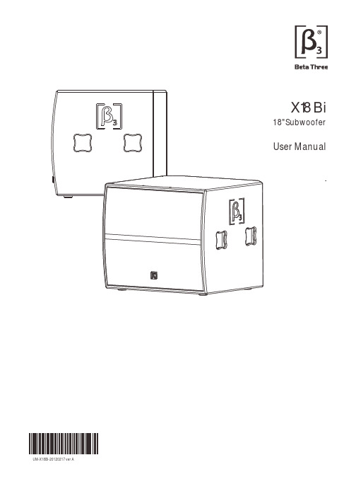
UM-X18Bi-20120217 ver AX18Bi18"SubwooferUser Manual11. 2. 3. 4. 5. 6. 7. 8. 9. 10. Read the instruction first before using this product.Pay attention to all warnings.Obey all operating instructions.Do not expose this product to rain or moisture.Do not block any ventilation openings. Install according to instructions .Do not install this product near any heat source, such as , heater, burner, or any other equipment with heat radiation .Only use spare parts by manufacturer.Pay attention to the safety symbol on the of the cover.manual Please keep this manual for future reference Clean this equipment with a dry cloth.manufacturer's a supplied theoutside PLEASE READ THIS MANUAL FIRSTThank you for a buying product. Read this manual first as it will help you operate the system properly. Please keep this manual for future reference.WARNING:This product must be installed by professionals. When using hanging brackets or rigging other than those supplied withthe product, please ensure they comply with the local safety codes.The exclamation point within an equilateral triangle is intended to alert you to the presence of important operating and servicing instructions.ATTENTION: Don't refit the system or spare parts without being authorized as this will .void the warranty WARNING: Don't (such as candles) the equipment.place naked flames close to2X18BiCONTENTProduct information subjects to be updated without notification, please visit for latest update.4533334446667CONTENTFeatures Description Applications Frequency Response And Impedance Curve CONNECTIONNL4 ConnectionINSTALLATIONINTRODUCTIONSystem Connection Reference Technical Sheet2D DimensionTECHNICAL SPECIFICATIONSpeakon 18"Subwoofer3X18BiX18Bi18"SubwooferFeaturesDescriptionINTRODUCTIONSingle 18phase inverted subwoofer."Computer aided design to optimize frequency and phase response.Frequency response range: 36Hz - 2kHz (-3dB).Sensitivity 97dB, MAX.SPL 121dB/127dB (PEAK).Rated power 500W, 2000W (PEAK).ApplicationsBars and Dancing halls Night Clubs Touring Clubs18"SubwooferX18Bi is a compact low frequency speaker system applied to small and medium-sized spaces that require high reliability. Arrayed with X8i and X12i full range speakers to form a high-performance full-range system. X18Bi adopts a 18-inch woofer, which achieves a fast transient response. The low-frequency driver uses 100mm high power voice coil rounded with copper wire inside and outside. The voice coil skeleton is made of high-strength TIL materials to make voice coil more strengthful and power handling. The RMS is 500W, short-term maximum power can be 2000W(GB/T9396-1996standard). Symmetrical magnetic circuit design makes odd harmonic distortion much lower, which fully satisfied the requirement of low-frequency sound. Equipped with XC2.6professional speaker controller can be realized modular quick adjustments.X18Bi adopts multifunctional structure design that is suitable for touring or fixed installation. The cabinet is made of wood laminate with Polyurethane spray processing to have superior weather resistance. X18Bi can be fast and reliably installed under different environments.4X18BiNL4LFNL4CONNECTIONTwo NL4 connectors are available for amplifier connections. Paralelled connector is very convenient for another speaker connection.Attention: The impedance of connected speaker must match the impedance of amplifier output.Attention: Make sure the polarity of speaker and amplifier correctly.System Connection ReferenceNL4 Connection1. Connect2. DisconnectTerminal Plate18"SubwooferX18Bi18"Subwoofer Warning:Make sure the mounting accessoriessafety factor not less than 5:1 or meet the localstandard during installation .INSTALLATIONInstallation Reference56S e n s i t i v i t y (d B )2070809010011012020050126Frequency (Hz )I m p e d a n c e (O h m s )501002005002k5k10k20k1k10025X18Bi18"SubwooferFrequency Response And Impedance CurveTECHNICAL SPECIFICATIONSpeaker Testing Method1. Frequency responseUse Pink noise to test the speaker in the anechoic room, adjust the level to make the speaker work at its rated impedance and the power output is 1W, then test the frequency response 1m away from the speaker.2. SensitivityUse full range Pink noise which was modified by EQ curve to test the speaker in the anechoic room, enlarge the signal to make the speaker work at its rated impedance and the power output is 1W, then test the sensitivity 1m away from the speaker.3. MAX.SPLUse full range Pink noise which was modified by EQ curve to test the speaker in the anechoic room, enlarge the signal to make the speaker work at its instant power output level, then test the SPL 1m away from the speaker.4. Rated PowerUse the pink noise according to IEC#268-5 to test the speaker, enlarge the signal for continuous 100hours, the rated Power is the power when the speaker will not incur hot damage or mechanics damage.1 x 18LF "Technical SheetPassive full range wooden speaker System:System components :36Hz-2kHz 1Frequency response(-3dB):97dB8 Ohms121dB/127dB(PEAK)4500W (RMS)1000W (MUSIC)2000W (PEAK )23Sensitivity(1W@1m):Max.SPL(1m):Power:Rated impedance:Handle: 4 x Wooden handlesCabinet coated by Polyurethane paint;grille is powder coated Painting: Cabinet dimension:(W x D x H)Package dimension:N.W.(pc):G.W.(pc):Connector:Nl4 x 250.5kg(111.1 lbs)54.5kg(119.9 lbs)750 x 690 x 630mm (29.5 x 27.2 x 24.8in)880 x 800 x 775mm (34.6 x 31.5 x 30.5in)(W x D x H)7X18Bi630m m (24.8i n )750mm(29.5in)18"SubwooferTECHNICAL SPECIFICATIONToy viewFront viewSide viewBack view2D DimensionNotes:。
- 1、下载文档前请自行甄别文档内容的完整性,平台不提供额外的编辑、内容补充、找答案等附加服务。
- 2、"仅部分预览"的文档,不可在线预览部分如存在完整性等问题,可反馈申请退款(可完整预览的文档不适用该条件!)。
- 3、如文档侵犯您的权益,请联系客服反馈,我们会尽快为您处理(人工客服工作时间:9:00-18:30)。
AMP1-SDA1U Digital Audio Speaker Monitorwith SDI Input and Loop-Through on BNCs,AES Digital Input on BNC, AES Output FromSDI on BNC, Two Analog Inputs on XLRs,Selected Stereo Analog Outputs on XLRs, Two26-Segment Level Meters, and Phase IndicationDocument P/N821531 Rev-BUser Manual© 2002 Wohler Technologies Inc. ALL rights reserved1© 2007Wohler Technologies, Inc. ALL rights reservedAMP1-SDA User Manual P/N 821531 Rev-BGeneral Featuresand SpecificationsDescriptionFeaturesApplicationsSpecificationsOther Options3© 2002 Wohler Technologies Inc. ALL rights reserved4© 2002 Wohler Technologies Inc. ALL rights reservedThe AMP-1 Digital series of audio monitors provides self-powered, full-fidelity stereo monitoring in the smallest rack space possible. All models in the AMP1 Digital series contain four high performance transducers driven by three power amplifiers: two amplifier/driver combinations handle midrange and high frequency information in stereo, while the third center channel reproduces information below the 500 Hz crossover point.All AMP1 Digital models come equipped with a ganged stereo volume control and balance pot, power indication LED, and headphone output. Output limiter circuits are incorporated to protect the speakers, and extensive magnetic shielding allows placement immediately adjacent to video monitors with no color impurities.The AMP1-SDA model features an SDI input and loop-through on BNC connectors, an AES input on an unbalanced BNC connector,an AES output (converted from the SDI input) on a BNC connector, analog inputs on two balanced XLR connectors, and a stereo analog output of the selected source on two XLR connectors. Toggle switches on the front panel allow selection of subgroup 1or 2(Channel 1/2 or 3/4) of the SDI input, SDI or AES input sources, and a choice of the selected digital source or the analog source inputs. Two red LEDs indicate the presence and error status of the selected AES and/or SDI signals entering the unit.Two high-resolution 26-segment tri-color LED bargraph level meters display the audio levels for the left and right selected sources.Wohlers proprietary three-LED stereo phase indication feature allows monitoring of phase relationships of the selected stereo inputs.AMP1-SD A1U Digital/Analog Audio Stereo Speaker Monitor• 98 dB SPL at two feet• Only one rack space high• Excellent high frequency response for positive detection ofbackground whine and noise• Audible and visual indication of phase/polarity problems• Thorough magnetic shielding for placement next to videomonitors• Two high-resolution 26-segment tri-color LED bargraphlevel meters• SDI input and loop-through on unbalanced BNC connectors• AES/EBU input on unbalanced BNC connector• Analog stereo inputs on two balanced XLR connectors• AES output (converted from SDI input) on BNC connector • Analog output of selected input on two balanced XLR connectors • SDI signal status indication LED • AES signal status indication LED • SDI subgroup 1 or 2 (of Group I.D. #1) source selection via front panel toggle switch • SDI/AES source selection via front panel toggle switch • Digital/analog source selection via front panel toggle switch • Headphone output • Power indication LED • Numerous control and input options • Quick and easy installation: simply slide in the rack and connect audio and AC powerThe AMP1 Digital series is ideally suited for use in VTR bays, mobile production vehicles, teleconferencing installations, multimedia systems, satellite links and cable TV facilities, and on-air radio studios. Designed and manufactured in the U.S., the AMP1-SDA is backed by a strong warranty and a satisfaction guaranteed return policy.AMP1-SDA Front PanelCE. 0 dbV ref. 0.775V RMS. Features and specifications subject to improvement without notice.5© 2002 Wohler Technologies Inc. ALL rights reserved6© 2002 Wohler Technologies Inc. ALL rights reservedAMP1-SDA User Manual P/N 821531 Rev-BInstallationFront Panel FeaturesRear Panel Features7© 2002 Wohler Technologies Inc. ALL rights reserved8© 2002 Wohler Technologies Inc. ALL rights reservedMountingNOTE: If you wish to set the AES Input Termination, AES Status Error Type, AES Input Level Gain, Line Level Calibration, Meter Gain Calibration, and/or Bargraph Display Mode via the DIP switches (accessed on the rear panel) be sure to do so BEFORE installing the unit into an enclosed rack or console. See pages 12 and 14 for setting information.The unit should be mounted where convenient for operating persons, ideally at approximately ear level for best high frequency response. Its superior magnetic shielding eliminates concerns about locating it adjacent to most types of CRT monitors, including even high-resolution color monitors.Heat DissipationHeat dissipated by the speaker amps is conducted directly to the left side of the chassis; no special considerations for cooling are necessary as long as the ambient temperature inside the rack area does not exceed approximately 40°C (104°F).Sympathetic VibrationSympathetic vibration from other equipment (cables, etc.,) in the rack may be serious enough to interfere with the unit’s sound quality out in the listening area. The use of thin card stock and/or felt or foam weather-stripping type materials between adjacent vibrating surfaces, or tying up loose cables, etc., may be required to stop vibrations external to the unit.Mechanical BracingEven though the unit is fairly heavy, the chassis is securely attached to the front panel at eight points along its surface, not just at the four corners of the chassis ears. This feature will reduce or eliminate rear bracing requirements in many mobile/portable applications. The weight of internal components is distributed fairly evenly around the unit.Audio ConnectionsConnection of the audio feeds is straightforward. Please refer to the system interconnect block diagram on page 22 for clarification of the general signal paths into and out of the AMP1-SDA unit.For digital inputs, Impedances are 75 Ω for the unbalanced BNC connectors and 110 Ω for the balanced XLR connectors. Analog inputs have an impedance of 40k Ω for the balanced XLR connectors.Care should be exercised to avoid mismatched cable types and other similar causes of undesired reflections in RF signal systems.Electrical InterferenceAs with any audio equipment, maximum immunity from electrical interference requires the use of shielded cable; however, satisfactory results can sometimes be obtained without it. The internal circuitry common is connected to the chassis.AC PowerThe unit's AC mains connection is via a standard IEC inlet, with safety ground connected directly to the unit's chassis. The universal AC input (100-240VAC, 50/60H z) switching power supply is a self-resetting sealed type, with automatic over-voltage and over-current shutdown. There is no user-replaceable fuse in either the primary or secondary circuit.9© 2002 Wohler Technologies Inc. ALL rights reservedPlease refer to Figure-2a on the following page to familiarize yourself with the front panel features of the AMP1-SDA unit. The following sections describe these functions and are referenced, by number, to Figure-2a.1 SpeakersThe AMP1-SDA internal speaker system is comprised of two mid-range speakers (left and right) and two woofer speakers (left and right). The two mid-range speakers reproduce, in stereo, only the mid and high frequencies, while the two woofer speakers monorally reproduce the low frequencies.2Volume Control - Rotary PotThis controls the loudness of the audio reproduced by the internal speakers or connected headphone.3 Headphone Output - 1/4" JackWhen you plug in headphones, the internal speakers will mute. This jack accepts a standard 1/4” phone type stereo plug. 4Power Indication - Green LEDThis LED glows green to indicate the AMP1-SDA is connected to operational mains power.5Phase Indication - Bi-Color LEDs (red/green)These three LEDs offer instant visual verification of phase (polarity) conditions in the pair of channels selected for monitoring in the Left/Right channel speakers. The two smaller LEDs, labeled Φ+andΦ-(above and below), show instantaneous phase relationships in the signal, while the larger LED, labeled "A VG" (center), indicates the average phase condition.The small Φ+ LED (top) glows (or blinks) green when signals are in-phase. The small Φ- LED (bottom) glows (or blinks) amber for out-of-phase signals. The larger A VG LED (middle) indicates the average phase condition by glowing green for in-phase conditions, or red for out-of-phase conditions.In general, it is sufficient to regard the A VG LED (average phase condition) as adequate for proper phase monitoring. While it is normal for stereo signals to contain some intermittant instantaneous out-of-phase and in-phase conditions (small LEDs),a steady red glow of the larger LED almost always indicates an out-of-phase alarm condition.6 Audio Level Meters - 26-Segment LED Bargraph DisplaysAudio levels for the selected input sources are displayed via these two 26-segment tri-color (green, amber, red) LED bargraph display level meters. These two bargraph displays are user adjustable for Line Level Calibration,Meter Gain Calibration, and Bargraph Display Mode via a DIP switch on the rear panel. See Item H on page 14 for more information regarding the level meter DIP switch location and settings.7 Bargraph Brightness Adjust - Recessed Trim PotThis control is recessed into the front panel and can be accessed using a small flathead screwdriver. Turning the trim pot clockwise will simultaneously increase the relative brightness of the LED segments in both bargraphs.8 SDI Signal Status Indication - Bi-Color LED (Green/Red)This LED indicates the status of any SDI signal entering the unit regardless of any monitor selection settings. This LED is OFF when no valid SDI signal is present, GREEN when a valid signal is present, or RED when the signal is not properly received or audio is not de-embedded.9 AES/EBU Signal Status Indication - Bi-Color (Green/Red) LEDThis LED indicates the status of any AES signal entering the unit regardless of any monitor selection settings. This LED is GREEN when a valid signal is present, or RED to indicate errors. There are two DIP switch selectable modes of fault detection that will create a RED LED error indication. See Item C, page 12 for more information about this setting.10SDI/AES Source Select - 2-Position Toggle SwitchThis switch selects between the AES and SDI input sources (Item E, page 12 and Item G, page 14). However, to monitor either of these selected digital sources, the Analog/Digital Source Select switch (Item 12) must be set set to DIGITAL. 11SDI Group Select - 2-Position Toggle SwitchThis switch selects between GROUP 1 (subgroup 1, channels 1/2) and GROUP 2 (subgroup 2, channels 3/4) to be monitored within the SDI input stream. All available subgroups/channels are derived from SDI Group I.D. #1.12Analog/Digital Source Select - 2-Position Toggle SwitchWhen this toggle switch is set to ANALOG, the unit will monitor the analog input signals from the ANALOG IN XLR connectors on the rear panel (Item B, page 12). When this toggle switch is set to DIGITAL, the unit will monitor the digital source (SDI or AES) as selected by the SDI/AES Source Select switch (Item 10).13Balance Control - Rotary PotThis pans the volume balance between the left and right speakers. If the balance is adjusted hard left or hard right, a slight left/right channel mix is retained (only in low bass frequencies) so that phase discrepancies can be audibly discerned.10© 2002 Wohler Technologies Inc. ALL rights reservedPlease refer to Figure-2b on the following page to familiarize yourself with the rear panel features of the AMP1-SDA unit. Thefollowing sections describe these features and are referenced, by letter, to Figure-2b.A Power - IEC-320 ConnectorAttach a standard IEC-320 power cord between this connector and mains power (100 - 250VAC, 50/60 Hz). The front panel power LED (Item 4, page 10) will glow green to indicate operating voltages are present.B Analog Inputs (Channel A (L) and Channel B (R) - 3-Pin Female XLR ConnectorsThese two balanced (40k Ω) XLR connectors accept standard analog audio signals. The unit will monitor signals input on these two connectors when the Analog/Digital Source Select switch on the front panel (Item 12, page 10) is set to ANALOG .For XLR pinout information see the diagram at the bottom of page 14.C AES/EBU Termination and AES Error Fault Type - 4-Section DIP SwitchAES Input Termination: In the event that the AES input channel is fed to downstream equipment (via a "Y" or "T"connector), then DIP switch Section S2 must be placed in the Unterminated (UP ) position. If there is no downstream equipment connected, then Section S2 must be placed in the Terminated (DOWN ) position. See below left for diagram of termination settings.Note: Sections S3 (x) and S4 (Term 2) are not used.AES Error Indication Fault Type: There are two DIP switch selectable modes of fault detection that will create a red error indication in the AES/EBU Signal Status Indication LED;1) Reception errors: errors in reception of data or no data stream at all (S1=DOWN )or 2) Reception and data errors: errors in reception and data errors identified by the sending device (possibly invalid) (S1=UP ). See below right for diagram of AES error settings.Note: Sections S3 (x) and S4 (Term2) are not used.D AES Out (From SDI) - Female BNC ConnectorsThe AES/EBU OUT connector outputs an AES/EBU signal as converted from the SDI input and as selected by the SDI Group Select switch (Item 11, page 10). This connector is configured for an unbalanced, 75 Ω connection.E AES/EBU In - Female BNC ConnectorsThe AES/EBU IN input connector is meant to receive standard AES/EBU signals. This BNC connector is configured for an unbalanced, 75 Ω connection. Note that the unit will monitor the AES/EBU input only when the Analog/Digital Source Select switch (Item 12, page 10) is set to DIGITAL and the SDI/AES Select switch (Item 10, page 10) is set to AES .F AES/EBU Input Level Gain Calibration - 2-Section DIP SwitchInput Level Gain Calibration, the analog level which corresponds to a given digital input value, is settable via this DIP switch.The factory setting is +4 dB (analog) = -20 dBFS (digital). See the silk-screened chart on the rear panel or the diagram below for Gain Calibration settings.G SDI In and Out - Female BNC ConnectorsThe SDI IN input connector is meant to receive standard SDI signals. The SDI OUT loop-through connector outputs a reclocked (regenerated) copy of the signal entering the SDI IN input connector. Both connectors are configured for unbalanced, 75Ω connections. Note that the unit will monitor the SDI input only when the Analog/Digital Source Select switch (Item 12, page 10) is set to DIGITAL and the SDI/AES Select switch (Item 10, page 10) is set to SDI.H Level/Gain Calibration and Display Mode - 6-Position DIP SwitchThis DIP switch sets the Line Level Calibration, Meter Gain Calibration, and Bargraph Display Mode.Line Level Calibration: The unit is calibrated at the factory. To recalibrate:1)Turn on the power.2) Apply a reference level (nominal 0) signal to all four channels.3)Make sure the Gain Calibration DIP sections (S2,S3) are set to the nearest level (i.e., 0, +4, +6 or +8).4) Place section S1 of the DIP switch in the DOWN position.5) Wait 10 seconds. The unit will remove the previous calibration. The unit will make sure that all four channels are within+/- 4 dB of nominal zero. If all four channels are within this range then the new calibration will be applied. If any channel is outside this range then no new calibration will be applied.6) Place section S1 of the DIP switch in the UP position and return unit to service.If one wishes to calibrate again, turn off the power to the unit and repeat steps 1 through 6. See diagram below for settings.Meter Gain Calibration: DIP switch sections S2 and S3 determine the Gain Calibration, which adjusts the level of the input signal and the resultant "0" level displayed on the LED bargraphs. Factory setting is +4 dB. See diagram below for all settings.Bargraph Display Mode: DIP switch sections S4 and S5 determine how peak levels are displayed for the four associated meters on the front panel. S4 selects either the PPM level or a new auto-reset Peak Hold of the VU level (NOT the PPM value). When S3 is set for "VU Peak", S5 sets the Hold time to either 3 or 10 seconds. If S4 is set for "PPM Peak", S5 determines whether it is displayed in the original "floating PPM dot" mode (no hold, continuous decay of 20 dB in 1.5 seconds) or as a 3 second auto-reset Hold. The factory default setting is "PPM Peak - No Hold" (continuous decay of 20 dB in 1.5 seconds). See diagram below for all settings.Note: Section S6 on the DIP switch is not used.I Selected Analog Outputs (from Digital Source) - 3-Pin Male XLR ConnectorsThe SEL. OUT [CH A(L) and CH B(R)] output connectors are analog outputs of the selected digital source as selected for the left and right speakers and level meters. Both connectors are configured for low impedance connections. The output is not affected by the volume/balance controls or headphone mute. For all XLR pinout information see the diagram below.Gnd Pin-2Pin-1Gnd Pin-2Low (-)Female XLR PinoutTechnical Information• General Technical Observations• SDI to AES Converter Module (919096)• AES/EBU to Analog Converter Module Circuit Description (919117)• General Level Meter PCB Descriptions• LED Bargraph Level Meter Specifications• AMP1-SDA Interconnect Block DiagramGeneral Mechanical ObservationsElimination of cabinet and component sympathetic vibrations (resonances) requires considerable attention to mechanical details. Because of this, and the physical constraints of the speaker’s acoustic enclosures, even minor changes to any of the mechanical details of the unit can seriously impair its acoustic performance. This especially applies to the speaker baffles. If mechanical work on the unit is necessary, be sure to make adequate notes to permit accurate reassembly.Unfortunately, the unusual and wholly proprietary method of magnetic shielding is usually degraded slightly by any disassembly of the unit, except removal of the rear panel. Almost any maintenance or repair will require removal of the cover. If an immediately adjacent video monitor shows magnetic interference after reassembly of the unit, it must be returned to the factory to restore the shielding completely.General Audio Circuitry ObservationsSince a single-sided power supply is used, all amplifier sections are “biased” with a 1/2 supply reference, so all opamp signal terminals on the main board should have a DC level of +12V, +/-0.7V. Signal inputs to the main audio board from any of the input select circuits are via the balanced input stage, in lieu of the XLR analog inputs on the basic unit. Signal feed points for level meters and the phase indicator are immediately after the input stage, and before the volume control section.The signal pick-off for the headphones is after the volume and balance controls. Speaker muting is controlled by circuitry that senses connection of headphones to the jack.The power amps are attached to an aluminum heatsink plate (which is also connected to the circuit common for these devices). The heatsink plate forms an operational module separate from the chassis, which allows access to the solder side of the circuit board while power is applied to the circuitry. To avoid thermal shutdown of the power amp(s), they should NOT be operated without their tabs being fastened to the heatsink plate.Variations in the frequency response of different production runs of drivers has sometimes required minor adjustments in the equalization/crossover components in individual runs of units. Some of these components may have values slightly different than those indicated in the schematic, which are the nominal ones. If any of the drivers (speakers) are replaced, it may be helpful to change some of these components to achieve maximum flatness of response.The operating threshold of the woofer limiter is critical to both satisfactory reproduction of musical transients and preventing damage to, or destruction of, the speaker itself. The side speaker output limiter circuits are similarly important, though not as critically adjusted.The woofer power amps are arranged in a bridge configuration; care must be taken to avoid letting EITH ER speaker terminal contact the chassis (common) OR THE GROUNDED LEAD OF ANY TEST EQUIPMENT so as not to short out the power amps. The side speaker outputs are single-ended, so these precautions are not necessary for them.The 919096 (Serial Digital to AES/EBU Converter PCB) allows selected Wohler Technologies audio monitoring systems to be connected directly to a serial digital video signal containing embedded audio. Two levels of component signals (eg., D1, D5, and Digi Betacam type) are currently supported; synchronous audio at 48 KHz with either 20-bit data packets or audio and extended data packets. The 919096 demultiplexes (extracts) the audio data from the video data, reformatting it to the AES/EBU standard. A companion digital to analog converter module (AES/EBU Input) is required to convert the AES/EBU signal to analog audio.A front panel toggle switch selects channels one and two (first subgroup) or channels three and four (second subgroup) from group i.d. #1 for demuxing. Access to group two through four is optional.There are four primary and three ancillary sections comprising the 719117 AES/EBU digital to analog converter:1) Input source selection.2) audio data extraction.3) Digital to analog conversion.4) Analog buffer/output amplifiers.5) Power suppy, Reset, and Error indication.Input Source Selection (IC13)Each of the two selectable signal inputs are transformer-coupled to the inputs of a one-of-two active buffer/switch (IC13). The output of this switch is applied to the receiver stage of the AES receiver/unframer.Audio Data Extraction (IC11)"Header" and ancillary data are removed from the recovered input datastream, yielding a datastream having only alternating left/right channel audio data which is output on pin 26 of IC11.Digital to Analog Conversion (IC10)The "pure" audio datastream, along with a data clock and a channel ID (left/right) clock, are applied to a 20 bit two channel D to A converter (IC10), where the datastream is converted into left and right analog outputs.Analog buffer (IC4) / Output Amplifiers (IC8, IC9)Buffer/amps provide balanced left and right channel outputs as well as single ended outputs. Gain calibration, the analog level which corresponds to a given digital value, is settable via a DIP switch. The default factory setting is 20 dB below "full code" (digital zero) to equal +4 dbu (0.775V). The other three settings possible are for -18 dBfs = 0 dBu, -9 dBfs = +6 dBu, and -20 dBfs = +8 dBu. See page 12 for DIP switch location and settings.Power SupplyThe 24V rail internal to the rest of the unit is converted to +5V for digital portions of the 919117 PCB by switching regulator IC12. Error IndicationThe AES status LED is a bicolor LED (Red/Green). It is green as long as a valid digital data strean is being received. The 8412 receiver is capable of distinguishing two types of error conditions: 1) Faulty data; data identified by the sending device (possibly invalid), or 2) Faulty reception; errors in reception of data or no data stream at all. The red LED indication may be set to occur for only faulty reception (section 1 closed) or with either faulty data OR faulty reception (section 1 open). See Item B, page 12 for more information regarding this setting.Power CharacteristicsA +5 voltage (DC) is fed directly to a 4-channel Input Level Meter Engine PCB (919174). Bargraph brightness is regulated from the Bargraph Driver PCB(s) (919173).4-Channel Input Level Meter Engine Boards (919174)The analog input signals or digital input signals (after conversion from digital to analog) are inputted to a discrete Input Level Meter Engine PCB. Each Input Level Meter Engine PC boards responsibility is to process tasks such as Digital Signal Processing (DSP),frequency response, integration time, VU or PPM “dot” display mode, and phase correlation (special order option). The ADSP-2184chip on each input board handles the entire processing function. During the assembly of an AMP1-SDA unit, software is programmed and loaded to a socket chip for a specific unit in-house.A standard factory calibration of "0" indication when input level is +4 dB is set for the calibration level unless specified differently by the end user. A bank of DIP switch sections is located at the rear of these boards, which can be accessed from the rear panel. A combination of DIP switch settings can be use to calibrate the line level input to "0", set the Gain Calibration, or select the Display Mode (VU, PPM). See page 14 for for information regarding these DIP switch settings.Bargraph Driver (919173) and Bargraph Display Boards (919172)All the signal information processed from the Input Level Meter Engine PC boards are transfered to the Bargraph Driver PC boards through a 10-pin color coded cable. The Bargraph Display PC board holds the actual LED bargraph modules at the front panel and is mounted in front of the Bargraph Driver PC board and connected to it directly by header/housing connections. The Bargraph Driver PC Boards accept fixed-length word serially, and latch the outputs for the bargraph segments corresponding to those bits in the received word, which are set high.Brightness of the bargraph displays can be adjusted to a desired setting by adjusting the trimpot located on the front panel. Both bargraph displays are simultaneously adjusted with this one trimpot.26-Segment Bargraphs with Analog ScaleLevel meter type:Segment quantity:Meter display modes (DIP switch selectable):PPM peak hold properties (DIP switch select):VU peak hold properties (DIP switch select):Level gain (DIP switch selectable):Level meter scale:Dynamic range:Midscale resolution:Bargraph Length:LED segment size:LED segment pitch:Segment display color:Peak emmision wavelength:Segment brighness, (If = 20 mA):Segment brightness, uniformity:Adjacent segment "Off" brightness:LED bargraph 26VU (bar)or PPM (dot)20 dB decay in 1.5 seconds or 3 second hold 3 second hold or 10 second hold 0, +4, +6, +8 dBu +12 to -50 dB 62 dB 2 dB1.078" (27.85 mm)0.14" x 0.028" (3.57 x 0.7 mm)0.041" (1.05 mm)Tri-color (red, amber, green)Green: 570 nm, Red: 630 nm 3.5 mcd<10% difference between segments <1% of brightness of active segmentSOURCEA M P 1-S D A I n t e r c o n n e c tB l o c k D i a g r a mS A n a l o g S A n a l o A n a l o g A n a l (F r o D i g i t D I (A A S L e f t W o o f e r S p e a k e re f t i d e p e a k e ri g h t i d e p e a k e rR i g h t W o o f e r S p e a k e r(R e v -A , 05/04/02)。