msi使用手册
MSI N1000a (v1.X) Network System用户手册说明书
(v1.X) Network Systemi1Thank you for choosing the N1000a, an excellent network system.The N1000a features Intel® Pentium® and Celeron® product families andthe industry’s latest technologies to deliver high-performance, feature-rich network solutions for a wide array of business applications.1-1-1System Overviewh System I/O & Controls123449101167851System Power ButtonPress the system power button to turn the system on or off.2System Reset ButtonPress the system reset button to reset the system.Antenna ConnectorThe antenna connector is provided for 3G/LTE/WiFi antennas.2This chapter provides you with the information on hardware setup proce-dures. While doing the installation, be careful in holding the componentsand follow the installation procedures. For some components, if you in-stall in the wrong orientation, the components will not work properly.Use a grounded wrist strap before handling computer components. Staticelectricity may damage the components.1-2-13This chapter provides information on the BIOS Setup program and allowsusers to configure the system for optimal use.Users may need to run the Setup program when:■An error message appears on the screen at system startup and requests users to run SETUP.■Users want to change the default settings for customized features.• Please note that BIOS update assumes technician-level experience.• As the system BIOS is under continuous update for better system performance, the illustrations in this chapter should be held forreference only.2-3-1MainUse this menu for basic system configurations, such as time, date, etc. AdvancedUse this menu to set up the items of special enhanced features.SecurityUse this menu to set supervisor and user passwords.BootUse this menu to specify the priority of boot devices.Save & ExitThis menu allows you to load the BIOS default values or factory default settings into the BIOS and exit the BIOS setup utility with or without changes.BIOS Information, Memory Information, SATA InformationThese items show the firmware and hardware specifications of your system. Read only.System DateThis setting allows users to set the system date. The date format is <Day>, <Month> <Date> <Year>.System TimeThis setting allows users to set the system time. The time format is <Hour> <Min ute> <Second>.CPU ConfigurationThis menu shows the processor information.▶EISTEIST (Enhanced Intel SpeedStep Technology) allows the system tonamically adjust processor voltage and core frequency, which can result in decreased verage power consumption and decreased average heat pro duction.▶C StatesC-state performance indicates the ability to run the processor in lower pow er states when the PC is idle. This setting enables/disables the C-State Configuration for power saving purposes.State After G3Select S0 or S5 for ACPI state after G3.Chassis IntrusionThis setting enables/disables the feature of recording the chassis intrusion status and issuing a warning message if the chassis is once opened. Primary DisplayThis setting selects the primary display.State After G3Select S0 or S5 for ACPI state after G3.Chassis IntrusionThis setting enables/disables the feature of recording the chassis intrusion status and issuing a warning message if the chassis is once opened.Console RedirectionConsole Redirection operates in host systems that do not have a monitor and keyboard attached. This setting enables/disables the operation of console re direction. When set to [Enabled], BIOS redirects and sends all contents that should be displayed on the screen to the serial COM port for display on the terminal screen. Besides, all data received from the serial port is interpreted as keystrokes from a local keyboard.Console Redirection SettingsTerminal TypeTo operate the system’s console redirection, you need a terminal support ing ANSI terminal protocol and a RS-232 null modem cable connected be tween the host system and terminal(s). This setting specifies the type of terminal device for console redirection.Bits per second, Data Bits, Parity, Stop Bitssetting specifies the transfer rate (bits per second, datastop bits) of Console Redirection.Wake System from S5This field specifies whether the RTC (real-time clock) alarm will awaken the system from the S5 power saving mode.Security Device SupportThis setting enables/disables BIOS support for security device. When set to [Disable], the OS will not show security device. TCG EFI protocol and INT1A interface will not be available.Administrator PasswordAdministrator Password controls access to the BIOS Setup utility. Users will be prompted for Administrator password only when they enter BIOS Setup.User PasswordUser Password controls access to the system at boot and access to the BIOS Setup utility. Users will be prompted for User password when they power the system or enter BIOS Setup. In BIOS Setup, users will have Administrator rights.Setup Prompt TimeoutThis setting specifies the number of seconds to wait for setup activation key. Bootup NumLock StateThis setting is to set the Num Lock status when the system is powered on. Setting to [On] will turn on the Num Lock key when the system is powered on. Setting to [Off] will allow users to use the arrow keys on the numeric keypad.Quiet BootThis BIOS feature determines if the BIOS should hide the normal POST messag es with the motherboard or system manufacturer’s full-screen logo. When it is enabled, the BIOS will display the full-screen logo during the boot-up sequence, hiding normal POST messages.When it is disabled, the BIOS will display the normal POST messages, instead of the full-screen logo.Please note that enabling this BIOS feature often adds 2-3 seconds of delay to the booting sequence. This delay ensures that the logo is displayed for a suffiient amount of time. Therefore, it is recommended that you disable this BIOS feature for a faster boot-up time.Boot Option PrioritiesThe items allow you to set the sequence of boot devices where BIOS attempts to load the disk operating system. First press <Enter> to enter the sub-menu. Then you may use the arrow keys ( ↑↓ ) to select the desired device, then press <+>, <-> or <PageUp>, <PageDown> key to move it up/down in the priority list.Save Changes and ResetSave changes to CMOS and reset the system.Discard Changes and ResetAbandon all changes and reset the system.Restore DefaultsRestore the factory defaults.Boot OverrideThis setting allows booting from a specific device immediately.Launch EFI Shell from filesystem deviceThis setting helps to launch the EFI Shell application from one of the available file system devices.4This chapter provides information on system drivers.• Please note that firmware update assumes technician-levelexperience.• As the system firmware is under continuous update for better system performance, the illustrations in this chapter should be held forreference only.2-4-1Download Websitethe MSI website for technical guides, BIOS updates, driver updates other information.。
MSI 27英寸IPS屏Windows 11 Home系统电脑说明说明书
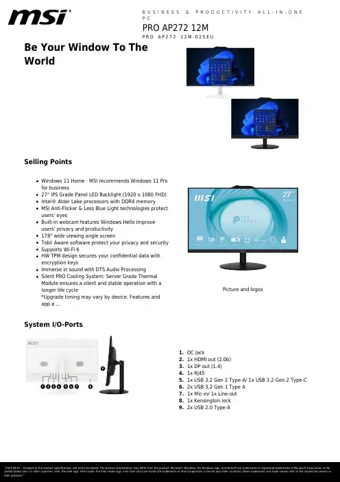
Be Your Window To TheWorldSelling PointsWindows 11 Home - MSI recommends Windows 11 Pro for business27" IPS Grade Panel LED Backlight (1920 x 1080 FHD)Intel® Alder Lake processors with DDR4 memoryMSI Anti-Flicker & Less Blue Light technologies protect users' eyesBuilt-in webcam features Windows Hello improve users’ privacy and productivity 178° wide viewing angle screenTobii Aware software protect your privacy and security Supports Wi-Fi 6HW TPM design secures your confidential data with encryption keysImmerse in sound with DTS Audio ProcessingSilent PRO Cooling System: Server Grade Thermal Module ensures a silent and stable operation with a longer life cycle*Upgrade timing may vary by device. Features and app a ...Picture and logosSystem I/O-PortsDC Jack1.1x HDMI out (2.0b)2.1x DP out (1.4)3.1x RJ454.1x USB 3.2 Gen 2 Type-A/ 1x USB 3.2 Gen 2 Type-C5.2x USB 3.2 Gen 1 Type A6.1x Mic-in/ 1x Line-out7.1x Kensington lock8.2x USB 2.0 Type-A9.SpecificationOperating Systems Windows Windows 11 ProDisplay Screen Size27" (69 cm)Active Display Area (mm)N/ACurvature FlatPanel Type IPSResolution1920x1080 (FHD) Pixel pitch0.2745(H)X0.2745(V) Brightness (nits)250Contrast Ratio1200:1Signal Frequency N/AResponse Time (GTG)14msView Angles178°(H)/178°(V) Surface Treatment Anti-GlareTouch Screen Non-touchDisplay Colors16.7MI/O Ports Lock type KensingtonProcessor CPU model Intel Core i7-12700CPU Clock 2.1GHzCPU Cores12CPU TDP65WCPU Cache25 MB Intel® Smart Cache CPU Threads20Chipset Motherboard Chipset H610Memory Memory Capacity16GB(8GB*2) Memory Type DDR4 SDRAM Memory Speed1600(3200)MHz Memory Module Form Factor SO-DIMM Memory Slot (Total/Free)2/0Memory Max Capacity Max 64GBStorage Total SSD Storage Capacity1TBTotal HDD Storage Capacity N/AM.2 Slot (1) Installed SSD1TB*1M.2 Slot (1) Interface PCIe GEN3x4 w/o DRAM NVMe M.2 Slot (1) Form Factor M.2-2280 M-KEYM.2 slots (Total/Free)1/0HDD (1) RPM N/AHDD (1) Form Factor N/AHDD (1) Interface N/A3.5" Drive Bays (Total/Free)0/2.5" Drive Bays (Total/Free)1/1ODD(Type)N/AODD Height N/AODD Type N/ACommunications LAN Controller Realtek RTL8111H Wireless LAN Controller INTEL/AX201.NGWG.NVW Wireless LAN standard802.11ax 2x2+BT Bluetooth Version 5.2Audio Audio Codec Realtek ALC897 Audio Support 2.1 Channel HD AudioI/O Ports (Front)USB 480Mbps (USB 2.0)2I/O Ports (Rear)USB 5Gbps (USB 3.2 Gen 1 Type-A)4LAN Ports (RJ45)1HDMI™1x (v1.4) COM Port1Power AC Adapter Output120W Battery N/A Battery Whrs N/AIn The Box Keyboard Interface N/A Mouse Interface N/A Power Cord1 AC Adaptor1 Warranty Card N/A Quick Guide2 User Manual N/A VESA Mount kit N/A Keyboard N/A Mouse N/ARegulatory Compliance Storage Operating Temperature Range0° C ~ 35° C ; -20° C ~ 60° C Storage Operating Humidity Range0% ~ 85%;0% ~ 90%CertificationsFCC(Class B)CB/CEUL(CUL)BSMIDesign Adjustment (Tilt)-5°~20°(+/-2°) Adjustment (Swivel)N/A Adjustment (Height)N/A Adjustment (Pivot)N/AProduct Dimension with Stand (WxDxH)Product Dimension with Stand (WxDxH) (mm)541.9 x 227.9 x 425.5 Product Dimension with Stand (WxDxH) (inch)21.33 x 8.97 x 16.75Dimension & Weight Weight (Net kg) 4.63Weight (Gross kg)8Product Dimension with Holder (WxDxH) (mm)N/AProduct Dimension with Holder (WxDxH) (inch)N/AInside Carton Dimension with Holder (WxDxH)(mm)N/AInside Carton Dimension with Holder (WxDxH)(inch)N/AInside Carton Dimension with Stand (WxDxH)(mm)696 x 218 x 490 Inside Carton Dimension with Stand (WxDxH)(inch)27.4 x 8.58 x 19.29 Outer Carton Dimension with Holder (WxDxH)(mm)N/AWarranty Warranty36M。
MSI H410M PRO 主板用户手册说明书
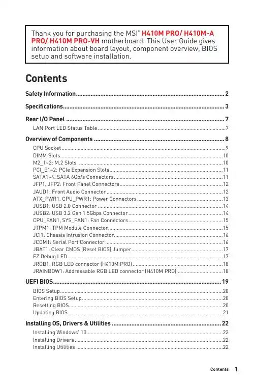
1ContentsContentsSafety Information ...........................................................................................2Specifications ...................................................................................................3Rear I/O Panel .................................................................................................7LAN Port LED Status Table . (7)Overview of Components (8)CPU Socket .................................................................................................................9DIMM Slots................................................................................................................10M2_1~2: M.2 Slots ...................................................................................................10PCI_E1~2: PCIe Expansion Slots ..............................................................................11SATA1~4: SATA 6Gb/s Connectors ...........................................................................11JFP1, JFP2: Front Panel Connectors .......................................................................12JAUD1: Front Audio Connector ................................................................................12ATX_PWR1, CPU_PWR1: Power Connectors ...........................................................13JUSB1: USB 2.0 Connector ......................................................................................14JUSB2: USB 3.2 Gen 1 5Gbps Connector .................................................................14CPU_FAN1, SYS_FAN1: Fan Connectors .................................................................15JTPM1: TPM Module Connector ...............................................................................15JCI1: Chassis Intrusion Connector ...........................................................................16JCOM1: Serial Port Connector .................................................................................16JBAT1: Clear CMOS (Reset BIOS) Jumper ...............................................................17EZ Debug LED ...........................................................................................................17JRGB1: RGB LED connector (H410M PRO) ..............................................................18JRAINBOW1: Addressable RGB LED connector (H410M PRO) ...............................18UEFI BIOS . (19)BIOS Setup ................................................................................................................20Entering BIOS Setup .................................................................................................20Resetting BIOS ..........................................................................................................20Updating BIOS...........................................................................................................21Installing OS, Drivers & Utilities . (22)Installing Windows ® 10..............................................................................................22Installing Drivers ......................................................................................................22Installing Utilities .. (22)Thank you for purchasing the MSI ® H410M PRO/ H410M-A PRO/ H410M PRO-VH motherboard. This User Guide gives information about board layout, component overview, BIOS setup and software installation.Safety Information∙The components included in this package are prone to damage from electrostatic discharge (ESD). Please adhere to the following instructions to ensure successful computer assembly.∙Ensure that all components are securely connected. Loose connections may cause the computer to not recognize a component or fail to start.∙Hold the motherboard by the edges to avoid touching sensitive components. ∙It is recommended to wear an electrostatic discharge (ESD) wrist strap when handling the motherboard to prevent electrostatic damage. If an ESD wrist strap is not available, discharge yourself of static electricity by touching another metal object before handling the motherboard.∙Store the motherboard in an electrostatic shielding container or on an anti-static pad whenever the motherboard is not installed.∙Before turning on the computer, ensure that there are no loose screws or metal components on the motherboard or anywhere within the computer case.∙Do not boot the computer before installation is completed. This could cause permanent damage to the components as well as injury to the user.∙If you need help during any installation step, please consult a certified computer technician.∙Always turn off the power supply and unplug the power cord from the power outlet before installing or removing any computer component.∙Keep this user guide for future reference.∙Keep this motherboard away from humidity.∙Make sure that your electrical outlet provides the same voltage as is indicated on the PSU, before connecting the PSU to the electrical outlet.∙Place the power cord such a way that people can not step on it. Do not place anything over the power cord.∙All cautions and warnings on the motherboard should be noted.∙If any of the following situations arises, get the motherboard checked by service personnel:▪Liquid has penetrated into the computer.▪The motherboard has been exposed to moisture.▪The motherboard does not work well or you can not get it work according touser guide.▪The motherboard has been dropped and damaged.▪The motherboard has obvious sign of breakage.∙Do not leave this motherboard in an environment above 60°C (140°F), it may damage the motherboard.2Safety Information3Specifications4Specifications5SpecificationsPlease refer to http:///manual/mb/DRAGONCENTER2.pdf formore details.6SpecificationsH410M-A PRO)Audio 7.1-channel ConfigurationTo configure 7.1-channel audio, you have to connect front audio I/O module to JAUD1 connector and follow the below steps.1. Click on the Realtek HD Audio Manager > Advanced Settings to open the dialog below.2. Select Mute the rear output device, when a front headphone plugged in.3. Plug your speakers to audio jacks on rear and front I/O panel. When you plug intoa device at an audio jack, a dialogue window will pop up asking you which device is current connected.7Rear I/O PanelOverview of Components* Distance from the center of the CPU to the nearest DIMM slot. 8Overview of Components9Overview of ComponentsImportant∙Always unplug the power cord from the power outlet before installing or removing the CPU.∙Please retain the CPU protective cap after installing the processor. MSI will deal with Return Merchandise Authorization (RMA) requests if only the motherboard comes with the protective cap on the CPU socket.∙When installing a CPU, always remember to install a CPU heatsink. A CPU heatsink is necessary to prevent overheating and maintain system stability.∙Confirm that the CPU heatsink has formed a tight seal with the CPU before booting your system.∙Overheating can seriously damage the CPU and motherboard. Always make sure the cooling fans work properly to protect the CPU from overheating. Be sure to apply an even layer of thermal paste (or thermal tape) between the CPU and the heatsink to enhance heat dissipation.∙Whenever the CPU is not installed, always protect the CPU socket pins by covering the socket with the plastic cap.∙If you purchased a separate CPU and heatsink/ cooler, Please refer to the docu-mentation in the heatsink/ cooler package for more details about installation.10Overview of ComponentsImportant∙Always insert memory modules in the DIMMA1 slot first.∙To ensure system stability for Dual channel mode, memory modules must be of the same type, number and density.∙Some memory modules may operate at a lower frequency than the marked value when overclocking due to the memory frequency operates dependent on its Serial Presence Detect (SPD). Go to BIOS and find the DRAM Frequency to set the memory frequency if you want to operate the memory at the marked or at a higher frequency. ∙It is recommended to use a more efficient memory cooling system for full DIMMs installation or overclocking.∙The stability and compatibility of installed memory module depend on installed CPU and devices when overclocking.∙Please refer for more information on compatible memory.M2_1~2: M.2 SlotsPlease install the M.2 device into the M.2 slot as shown below.13StandoffSupplied11Overview of Componentsunplug the power supply power cable from the power outlet. Read the expansion card’s documentation to check for any necessary additional hardware or software changes.∙If you install a large and heavy graphics card, you need to use a tool such as MSI Gaming Series Graphics Card Bolster to support its weight to prevent deformationof the slot.SATA1~4: SATA 6Gb/s ConnectorsThese connectors are SATA 6Gb/s interface ports. Each connector can connect to one SATA device.⚠Important∙Please do not fold the SATA cable at a 90-degree angle. Data loss may result during transmission otherwise.∙SATA cables have identical plugs on either sides of the cable. However, it is recommended that the flat connector be connected to the motherboard for space saving purposes.∙SATA4 will be unavailable when installing M.2 SATA SSD in the M.2 slot.JFP1, JFP2: Front Panel ConnectorsJAUD1: Front Audio Connector12Overview of ComponentsATX_PWR1, CPU_PWR1: Power ConnectorsImportantMake sure that all the power cables are securely connected to a proper ATX power supply to ensure stable operation of the motherboard.13Overview of Components14Overview of ComponentsJUSB2: USB 3.2 Gen 1 5Gbps ConnectorImportantNote that the Power and Ground pins must be connected correctly to avoid possible damage.JUSB1: USB 2.0 ConnectorImportant∙Note that the VCC and Ground pins must be connected correctly to avoid possible damage.∙In order to recharge your iPad,iPhone and iPod through USB ports, please install MSI® DRAGON CENTER utility.15Overview of ComponentsImportantYou can adjust fan speed in BIOS > Hardware Monitor.CPU_FAN1, SYS_FAN1: Fan ConnectorsPWM Mode fan connectors provide constant 12V output and adjust fan speed with speed control signal. When you plug a 3-pin (Non-PWM) fan to a fan connector in PWM mode, the fan speed will always maintain at 100%, which might create a lot ofnoise.JTPM1: TPM Module ConnectorThis connector is for TPM (Trusted Platform Module). Please refer to the TPMJCI1: Chassis Intrusion Connector(default)intrusion event Using chassis intrusion detector1. Connect the JCI1 connector to the chassis intrusion switch/ sensor on thechassis.2. Close the chassis cover.3. Go to BIOS > SETTINGS > Security > Chassis Intrusion Configuration.4. Set Chassis Intrusion to Enabled.5. Press F10 to save and exit and then press the Enter key to select Yes.6. Once the chassis cover is opened again, a warning message will be displayed onscreen when the computer is turned on.Resetting the chassis intrusion warning1. Go to BIOS > SETTINGS > Security > Chassis Intrusion Configuration.2. Set Chassis Intrusion to Reset.3. Press F10 to save and exit and then press the Enter key to select Yes. JCOM1: Serial Port Connector16Overview of ComponentsJBAT1: Clear CMOS (Reset BIOS) JumperThere is CMOS memory onboard that is external powered from a battery located on the motherboard to save system configuration data. If you want to clear the system(default)BIOSResetting BIOS to default values1. Power off the computer and unplug the power cord.2. Use a jumper cap to short JBAT1 for about 5-10 seconds.3. Remove the jumper cap from JBAT1.4. Plug the power cord and power on the computer.EZ Debug LEDThese LEDs indicate the status of the motherboard.CPU - indicates CPU is not detected or fail.DRAM - indicates DRAM is not detected or fail.VGA - indicates GPU is not detected or fail.BOOT - indicates booting device is not detected or fail.17Overview of ComponentsJRGB1: RGB LED connector (H410M PRO)Important∙The JRGB connector supports up to 2 meters continuous 5050 RGB LED strips (12V/G/R/B) with the maximum power rating of 3A (12V).∙Always turn off the power supply and unplug the power cord from the power outlet before installing or removing the RGB LED strip.∙Please use MSI’s software to control the extended LED strip. JRAINBOW1: Addressable RGB LED connector (H410M PRO)The JRAINBOW connector allows you to connect the WS2812B Individually Addressable RGB LED strips 5V.CAUTIONDo not connect the wrong type of LED strips. The JRGB connector and the JRAINBOW connector provide different voltages, and connecting the 5V LED strip to the JRGB connector will result in damage to the LED strip.⚠Important∙The JRAINBOW connector supports up to 75 LEDs WS2812B Individually Address-able RGB LED strips (5V/Data/Ground) with the maximum power rating of 3A (5V). In the case of 20% brightness, the connector supports up to 200 LEDs.∙Always turn off the power supply and unplug the power cord from the power outlet before installing or removing the RGB LED strip.∙Please use MSI’s software to control the extended LED strip.18Overview of ComponentsUEFI BIOSMSI UEFI BIOS is compatible with UEFI (Unified Extensible Firmware Interface) architecture. UEFI has many new functions and advantages that traditional BIOS cannot achieve, and it will completely replace BIOS in the future. The MSI UEFI BIOS uses UEFI as the default boot mode to take full advantage of the new chipset’s capabilities. However, it still has a CSM (Compatibility Support Module) mode to be compatible with older devices. That allows you to replace legacy devices with UEFI compatible devices during the transition.⚠ImportantThe term BIOS in this user guide refers to UEFI BIOS unless otherwise noted. UEFI advantages∙Fast booting - UEFI can directly boot the operating system and save the BIOS self-test process. And also eliminates the time to switch to CSM mode during POST.∙Supports for hard drive partitions larger than 2 TB.∙Supports more than 4 primary partitions with a GUID Partition Table (GPT).∙Supports unlimited number of partitions.∙Supports full capabilities of new devices - new devices may not provide backward compatibility.∙Supports secure startup - UEFI can check the validity of the operating system to ensure that no malware tampers with the startup process.Incompatible UEFI cases∙32-bit Windows operating system - this motherboard supports only 64-bit Windows 10 operating system.∙Older graphics card - the system will detect your graphics card. When display a warning message There is no GOP (Graphics Output protocol) support detected in this graphics card.⚠ImportantWe recommend that you to use a GOP/ UEFI compatible graphics card.How to check the BIOS mode?19UEFI BIOSBIOS SetupThe default settings offer the optimal performance for system stability in normal conditions. You should always keep the default settings to avoid possible system damage or failure booting unless you are familiar with BIOS.⚠Important∙BIOS items are continuous update for better system performance. Therefore, the description may be slightly different from the latest BIOS and should be held for reference only. You could also refer to the HELP information panel for BIOS item description.∙The BIOS items will vary with the processor. Entering BIOS SetupPress Delete key, when the Press DEL key to enter Setup Menu, F11 to enter Boot Menu message appears on the screen during the boot process.Function keyF1: General HelpF2: Add/ Remove a favorite itemF3: Enter Favorites menuF4: Enter CPU Specifications menuF5: Enter Memory-Z menuF6: Load optimized defaultsF7: Switch between Advanced mode and EZ modeF8: Load Overclocking ProfileF9: Save Overclocking ProfileF10: Save Change and Reset*F12: Take a screenshot and save it to USB flash drive (FAT/ FAT32 format only). Ctrl+F: Enter Search page* When you press F10, a confirmation window appears and it provides the modification information. Select between Yes or No to confirm your choice. Resetting BIOSYou might need to restore the default BIOS setting to solve certain problems. There are several ways to reset BIOS:∙Go to BIOS and press F6 to load optimized defaults.∙Short the Clear CMOS jumper on the motherboard.⚠ImportantPlease refer to the Clear CMOS jumper section for resetting BIOS.20UEFI BIOSUpdating BIOSUpdating BIOS with M-FLASHBefore updating:Please download the latest BIOS file that matches your motherboard model from MSI website. And then save the BIOS file into the USB flash drive.Updating BIOS:1. Insert the USB flash drive that contains the update file into the USB port.2. Please refer the following methods to enter flash mode.▪Reboot and press Ctrl + F5 key during POST and click on Yes to reboot the system.▪Reboot and press Del key during POST to enter BIOS. Click the M-FLASH button and click on Yes to reboot the system.3. Select a BIOS file to perform the BIOS update process.4. When prompted click on Yes to start recovering BIOS.5. After the flashing process is 100% completed, the system will reboot automatically.Updating the BIOS with Dragon CenterBefore updating:Make sure the LAN driver is already installed and the internet connection is set properly.Updating BIOS:1. Install and launch MSI DRAGON CENTER and go to Support page.2. Select Live Update and click on Advance button.3. Click on Scan button to search the latest BIOS file.4. Select the BIOS file and click on Download icon to download and install the latest BIOS file.5. Click Next and choose In Windows mode. And then click Next and Start to start updating BIOS.6. After the flashing process is 100% completed, the system will restart automatically.21UEFI BIOSInstalling OS, Drivers & UtilitiesPlease download and update the latest utilities and drivers at Installing Windows® 101. Power on the computer.2. Insert the Windows® 10 installation disc/USB into your computer.3. Press the Restart button on the computer case.4. Press F11 key during the computer POST (Power-On Self Test) to get into BootMenu.5. Select the Windows® 10 installation disc/USB from the Boot Menu.6. Press any key when screen shows Press any key to boot from CD or DVD...message.7. Follow the instructions on the screen to install Windows® 10. Installing Drivers1. Start up your computer in Windows® 10.2. Insert MSI® Driver Disc into your optical drive.3. Click the Select to choose what happens with this disc pop-up notification,then select Run DVDSetup.exe to open the installer. If you turn off the AutoPlayfeature from the Windows Control Panel, you can still manually execute theDVDSetup.exe from the root path of the MSI Driver Disc.4. The installer will find and list all necessary drivers in the Drivers/Software tab.5. Click the Install button in the lower-right corner of the window.6. The drivers installation will then be in progress, after it has finished it will promptyou to restart.7. Click OK button to finish.8. Restart your computer.Installing UtilitiesBefore you install utilities, you must complete drivers installation.1. Open the installer as described above.2. Click the Utilities tab.3. Select the utilities you want to install.4. Click the Install button in the lower-right corner of the window.5. The utilities installation will then be in progress, after it has finished it willprompt you to restart.6. Click OK button to finish.7. Restart your computer.22Installing OS, Drivers & Utilities。
MSI 迷你笔记本 SteelSeries Engine 使用手册说明书
[Troubleshooting] SteelSeries EngineThis document applies to all MSI Notebook which supports SteelSeries Engine.To know whether the product supports SteelSeries Engine or not, please visit MSI website and find the Overview page (Control) of your product.This document provides basic troubleshooting instructions for SteelSeries Engine and its common Q&A. Refer to the troubleshooting instructions if SteelSeries Engine doesn’t work properly, stops responding or crash unexpectedly. The common Q&A provides useful information when using SteelSeries Engine.Find the latest features, updates and fixes in SteelSeries Engine release note and follow the clean installation/update guide to perform the update.Outline1.Basic Troubleshooting (2)1.1.Confirm the Software Support (2)1.2.SteelSeries Engine Update (2)1.3.BIOS, EC Update & EC Reset (2)1.4.System Restore (2)1.5.Problem Report on Customer Support System (2)mon Q&A (3)1.Basic Troubleshooting1.1. Confirm the Software SupportMake sure that your notebook supports SteelSeries Engine by visiting theproduct Overview page (Control) on MSI website.1.2.SteelSeries Engine UpdateRefer to the general update guide to perform a clean installation of the latest SteelSeries Engine release on MSI website.1.3. BIOS, EC Update & EC ResetFollow the update guide to update the latest BIOS, EC firmware and do the EC reset. This may help re-initializing maltiple settings such as OC, keyboard and other power related setups.P.S. BOIS and EC update file can be found under product’s driver download page from MSI website.1.4. System RestoreIf the problem still remains after going through all steps above, try to restore the system back to the factory setting by using F3 recovery, Recovery Media created by MSI BurnRecovery tool or Windows 10 recovery function.1.5. Problem Report on Customer Support SystemIf the problem still remains after the system restore, create a ticket for theproblem on the online customer support system. Provide the systeminformation exported by using MSI Help Desk, detail problem symptomdescription and the clear problem replication steps.P.S. Provide the complete information (screen captures, recorded video, system information and the clear problem replication steps) can help shorten the troubleshooting time.mon Q&AQ: How to know if my notebook supports keyboard backlight adjustment?Visit the Specifications page of your product on MSI website, notebook which bundled with “Full-color backlighting SteelSe ries keyboard” supports keyboard backlight adjustment via SteelSeries Engine.*Note 1: Some old models support Keyboard Backlight Manager(KLM) for the keyboardbacklight adjustment function instead of SteelSeries Engine.*Note 2: 18“ series (e.g. GT80) do esn’t support the keyboard backlight adjustment eventhough it supports SteelSeries Engine, because it has only “Single color backlighting (red)SteelSeries keyboard”.Q: How can I enable the Audio mode for my keyboard backlight in SteelSeries Engine?When set the keyboard layout to Audio mode in SteelSeries Engine (SSE), the keyboard backlight only works when there is an audio signal playing (e.g. playing music, video…) from the speakers of the laptop with the volume 30% or above.*Note: If the speakers are muted or the audio is output from external devices via HDMI/DP connection, then the keyboard backlight won’t work.Q: Why does the keyboard backlight or the LED light on the front (e.g. GT72) isn’t lighting up?The keyboard backlight and the LED lights are controlled by the SteelSeriesEngine.If you have the self-installed system, make sure the SteelSeries Engine isinstalled properly.*Note: Visit the Utility download page of your product to download the latest SteelSeriesEngine.Q: How to avoid seeing blank options in SteelSeries Engine (SSE3) when running Windows 7 system with Chinese Tranditional or Simplified Chinese language?Update IE browser to IE 11 to avoid seeing the blank options in SteelSeriesEngine (SSE3).Q: What should I do if SteelSeries Engine stops working after performing the F3 system recovery?Refer to the update guide to re-install the latest SteelSeries Engine.Q: Why does the keyboard backlight keep flickering when playing games?This is a new feature “GAME SENSE” from SteelSeries Engine 3 which presents the game status (e.g. health and kills) of your character via keyboard backlight.*Note 1: Currently GAME SENSE supports DOTA2, CS:GO and MINECRAFT.*Note 2: Refer to the screen shot below for game settings of GAME SENSE.*Note 3: More SteelSeries Engine 3 introduction, please refer to the video tutorial.。
msi使用手册
msi使用手册摘要:1.MSI 使用手册概述2.MSI 的含义和作用3.MSI 的安装过程4.MSI 的卸载方法5.MSI 的使用注意事项正文:一、MSI 使用手册概述MSI(Microsoft Installer)是微软公司推出的一款软件安装程序,它可以帮助用户方便地安装、卸载和修复软件。
本文将为您详细介绍如何使用MSI,包括安装、卸载以及使用过程中的注意事项。
二、MSI 的含义和作用MSI(Microsoft Installer)是一种软件包安装程序,其主要作用是安装、卸载和修复软件。
通过MSI,用户可以方便地安装软件,同时可以避免软件安装过程中的一些常见问题,如版本冲突等。
三、MSI 的安装过程1.下载MSI 文件:首先,您需要从互联网上下载相应的MSI 文件。
通常,软件下载网站都会提供MSI 格式的文件。
2.双击运行MSI 文件:找到下载的MSI 文件,双击运行它。
这时,系统会自动启动MSI 安装程序。
3.按照提示进行操作:在安装过程中,您需要根据安装程序的提示进行操作,如选择安装目录、接受用户许可协议等。
4.等待安装完成:在完成上述操作后,您只需等待安装程序完成软件的安装。
四、MSI 的卸载方法1.通过“控制面板”卸载:打开“控制面板”,找到并点击“程序”,然后选择需要卸载的软件,点击“卸载”按钮。
2.通过MSI 命令卸载:打开命令提示符窗口,输入以下命令:```msiexec /i [软件的MSI 文件名].msi UNSIGNED```按回车键执行命令,按照提示操作,即可完成软件的卸载。
五、MSI 的使用注意事项1.在安装软件时,请确保选择正确的安装目录,以免影响其他软件的正常运行。
2.在卸载软件时,请务必按照提示进行操作,以免造成软件残留或系统损坏。
3.使用MSI 时,建议您在操作系统中启用“管理员”权限,以确保安装和卸载过程的顺利进行。
通过以上介绍,相信您已经了解了如何使用MSI 安装和卸载软件。
msi使用手册
msi使用手册摘要:1.MSI 使用手册概述2.MSI 的含义和作用3.MSI 的安装过程4.MSI 的使用方法5.MSI 的卸载方式6.MSI 的优点和局限性7.总结正文:一、MSI 使用手册概述MSI(Microsoft Installer)是微软公司推出的一种软件安装打包工具,广泛应用于Windows 操作系统中的软件安装与卸载。
本文将为您详细介绍如何使用MSI 制作安装包以及安装和使用软件。
二、MSI 的含义和作用1.MSI 的含义:MSI(Microsoft Installer)是微软公司推出的一种软件安装打包工具,它用于在Windows 操作系统上安装和卸载软件。
2.MSI 的作用:MSI 可以方便地制作软件安装包,实现软件的快速部署。
同时,MSI 具有较强的可定制性,可以根据需要自定义安装过程,满足不同用户的需求。
三、MSI 的安装过程1.准备工作:首先,需要下载并安装Visual Studio(建议使用VisualStudio 2010 及以上版本)。
2.打开Visual Studio,创建一个新的Windows Forms 应用程序项目。
3.在解决方案资源管理器中,右键单击项目名称,选择“添加”→“新建项”。
4.在弹出的对话框中,选择“安装程序”,然后点击“添加”。
5.在“安装向导”中,按照提示设置相关参数,如产品名称、公司名称、安装目录等。
6.在“安装选项”对话框中,可以选择安装方式(如典型安装、自定义安装等),以及需要安装的组件和功能。
7.在“完成安装向导”对话框中,确认设置无误后,点击“完成”。
四、MSI 的使用方法1.运行制作好的MSI 安装包,按照提示进行安装。
2.安装过程中,根据需要选择安装目录、组件和功能等。
3.安装完成后,可以运行安装的软件,并开始使用。
五、MSI 的卸载方式1.在“控制面板”中,找到并打开“程序和功能”。
2.在列表中找到需要卸载的软件,右键单击,选择“卸载”。
MSI G27C7 曲面游戏显示器说明书
See beyond the Game.Visualize your victory.Visualize your victory with MSI G27C7 Curved Gaming™ monitor.Equipped with a 1920x1080, 165hz Refresh rate, 1ms responsetime panel, G27C7 will give you the competitive edge you need totake down your opponents. Built with AMD Free sync premium,G27C7 can match the display's refresh rate with your GPU for ultra-smooth gameplay. Make sure you can hit your mark with all thelatest technologies built-in the MSI Curved Gaming™ monitor forcompetitive play.Picture and logos SELLING POINTS1500R曲面電競顯示器,滿足玩家沉浸於遊戲世界1920x1080 (FHD)165Hz刷新率 - 讓影像更加流暢、無殘影1ms反應時間有助於消除螢幕幀率不穩定情況產生廣色域-色彩表現最精準夜間模式-方便玩家針對遊戲中較昏暗的畫面進行螢幕的亮度調整AMD FreeSync -自動同步顯示卡及顯示器畫面更新率防閃爍減藍光設計,防止眼睛疲勞178°寬視角無邊框設計1.1x HDMI™ 1.42.1x HDMI™ 2.03.1x Display Port 1.2a4.1x DC Jack5.1x Earphone outSPECIFICATIONBarcode Info EAN4719072779726 UPC824142235393 UCC1410824142235390Model Part No9S6-3CC61Q-004 MKT Name Optix G27C7 MKT Spec Optix G27C7 Color ID1/Black-BlackDisplay Screen Size27" (69 cm)Active Display Area (mm)596.736 (H) x 335.664 (V) Curvature Curve 1500RPanel Type VAResolution1920x1080 (FHD)Pixel pitch0.3108(H)X0.3108(V)Aspect Ratio16:9Dynamic Refresh Rate technology FreeSync PremiumHDR (High dynamic range)N/ASDR Brightness (nits)250Contrast Ratio3000:1DCR (Dynamic Contrast Ratio)100000000:1Signal Frequency104~186.8 KHz(H) / 30~165 Hz(V) Activated Range48Hz~165HzRefresh Rate165HZResponse Time (MPRT)1ms(MPRT)Response Time (GTG)4msView Angles178°(H)/178°(V)Surface Treatment Anti-glareNTSC (CIE1976 area percentage/overlap)103%/84%NTSC (CIE1931 area percentage/overlap)85%/78%sRGB (CIE1976 area percentage/overlap)118%/99%sRGB (CIE1931 area percentage/overlap)120%/99%Adobe RGB (CIE1976 area percentage/overlap)101%/89%Adobe RGB (CIE1931 area percentage/overlap)89%/82%DCI-P3 (CIE1976 area percentage/overlap)94%/93%DCI-P3 (CIE1931 area percentage/overlap)89%/88%Rec.709 (CIE1976 area percentage/overlap)118%/99%Rec.709 (CIE1931 area percentage/overlap)120%/99%Display Colors16.7MColor bit8 bitsNote_DP1920 x 1080 (Up to 165Hz)Note_HDMI™1920 x 1080 (Up to 165Hz)Note_DVI N/AI/O Ports HDMI™2HDMI™ version 2.0HDMI™ HDCP version 2.2 DisplayPort1DisplayPort version 1.4 DisplayPort HDCP version 2.2 Headphone-out1Lock type Kensington LockPower Power Type External Adapter 19V 2.1A Power Input100~240V, 50/60HzEnergy Efficiency Rating FAdapter's KC safety Number HU10182-9054/HU10104-12329 Power Cord Type C5In The Box DisplayPort Cable1 HDMI™ Cable0 DVI Cable0 USB Type A to Type B Cable0 USB Type C to Type A Cable0 USB Type C to Type C Cable0 Thunderbolt Cable0 VGA Cable0 3.5mm audio Cable0 3.5mm combo audio Cable0 Power Cord1 AC Adaptor1 Warranty Card1 Quick Guide1Design Adjustment (Tilt)-5° ~ 20°VESA Mounting100x100mm Frameless Design YesOuter Carton Dimension (WxDxH)Outer Carton Dimension (WxDxH) (mm)711 x 181 x 488 Outer Carton Dimension (WxDxH) (inch)27.99 x 7.13 x 19.21Product Dimension with Stand (WxDxH)Product Dimension with Stand (WxDxH) (mm)611.3 x 228.4 x 447.5 Product Dimension with Stand (WxDxH) (inch)24.07 x 8.99 x 17.62Product Dimension without Stand (WxDxH)Product Dimension without Stand (WxDxH) (mm)611.3 x 78.3 x 372.5 Product Dimension without Stand (WxDxH) (inch)24.07 x 3.08 x 14.67Stand Dimension (WxDxH)Stand Dimension (WxDxH) (mm)474 x 228.4 x 267.3 Stand Dimension (WxDxH) (inch)18.66 x 8.99 x 10.52Dimension & Weight Inside Carton Dimension (WxDxH) (mm)696 x 166 x 463 Inside Carton Dimension (WxDxH) (inch)27.4 x 6.54 x 18.23 Weight (Net kg) 4.7Weight (Gross kg)7Warranty Warranty36M。
promega+msi分析系统, 1.2 版本+产品使用说明说明书
技术手册MSI Analysis System, Version 1.2 MSI分析系统, 1.2版本MD1641产品使用说明MSI 分析系统,1.2 版本1. 产品介绍 (2)1.A. MSI 分析系统 .............................................................................................................................................. 2 1.B. 微卫星不稳定性(MSI )简介 ................................................................................................................. 4 1.C. 内标(Internal Lane Standard 600, ILS 600) ........................................................................................ 4 2. 产品组分和储存条件 ............................................................................................................................................ 5 3. DNA 提取方法 ......................................................................................................................................................... 5 4. 用MSI 分析系统进行DNA 扩增 .. (6)4.A. 扩增体系的建立 ......................................................................................................................................... 6 4.B. 扩增循环参数的设置 ................................................................................................................................. 7 5. 使用ABI PRISM® 310遗传分析仪检测扩增片段 (9)5.A. Matrix 生成(或光谱校正) ...................................................................................................................... 9 5.B. 样品准备 ................................................................................................................................................... 10 5.C. 仪器准备 ................................................................................................................................................... 10 6. 用ABI PRISM® 3100遗传分析仪,用1.0.1或1.1版本的数据收集软件,检测扩增片段 (11)6.A. 光谱校正 ................................................................................................................................................... 11 6.B. 样品准备 ................................................................................................................................................... 12 6.C. 仪器准备 ................................................................................................................................................... 12 7. 使用ABI PRISM® 3100或3100-Avant 遗传分析仪,2.0版本的数据收集软件,或使用Applied Biosystems 3130或3130xl 遗传分析仪,检测扩增片段 ................................................................................................... 14 7.A. 光谱校正 ................................................................................................................................................... 15 7.B. 样品准备 ................................................................................................................................................... 15 7.C. 仪器准备 ................................................................................................................................................... 16 8. 数据分析 .. (17)8.A. MSI 分析概述 ............................................................................................................................................. 17 8.B. 将Panels 和Bins 文件导入GeneMapper®软件(4.0和4.1版本) ..................................................... 20 8.C. 用GeneMapper®软件(4.0和4.1版本)创建数据分析方法 .............................................................. 20 8.D. 创建片段大小标准(Size Standard ) ..................................................................................................... 22 8.E. 数据处理 ................................................................................................................................................... 23 8.F. 复审片段大小标准(Size Standard ) ...................................................................................................... 23 8.G. 复审样本数据分析 ................................................................................................................................... 23 9. 常见问题与解决方案 .......................................................................................................................................... 24 10. 附录 . (26)10.A. 相关产品 ................................................................................................................................................. 26 10.B. 单核苷酸重复基因座的等位基因频率 . (27)所有技术文献的英文原版均可在/protocols 获得。
msi使用手册
msi使用手册摘要:一、MSI概述与功能二、MSI的安装与配置三、MSI的使用方法与技巧四、MSI的高级功能与应用五、MSI的常见问题与解决方案六、MSI的升级与维护七、总结与建议正文:一、MSI概述与功能MSI(Microsoft System Image)是一款功能强大的系统映像制作工具,主要用于Windows操作系统的部署。
它可以帮助用户轻松创建和管理可启动的系统映像,以便在计算机出现问题时快速恢复。
MSI具有以下主要功能:1.创建可启动的系统映像2.部署操作系统、应用程序和驱动程序3.集成工具和脚本,实现自动化任务4.支持多种存储介质,如U盘、DVD或网络存储5.强大的压缩算法,减小映像文件大小二、MSI的安装与配置1.下载与安装:从官方网站或可靠来源下载最新版本的MSI,并根据安装向导完成安装。
2.配置环境:确保计算机满足MSI的系统要求,如CPU、内存和硬盘空间。
3.选择语言:在安装过程中,选择合适的操作系统语言。
4.输入许可证密钥:根据购买的许可证输入相应的密钥。
三、MSI的使用方法与技巧1.创建映像:选择“创建新映像”,根据向导选择操作系统、应用程序和驱动程序等信息。
2.导入现有映像:若已有MSI映像文件,可通过“导入现有映像”功能添加。
3.编辑映像:在映像编辑器中,可以添加、删除或修改组件。
4.压缩与加密:设置映像压缩级别和加密选项,以减小文件大小并提高安全性。
5.制作启动媒体:根据需求选择U盘、DVD或网络存储作为启动媒体。
6.部署映像:使用启动媒体引导计算机,按照屏幕提示完成部署过程。
四、MSI的高级功能与应用1.网络部署:通过局域网或互联网部署映像,实现远程安装。
2.无人值守安装:设置自动化安装脚本,实现无人值守的部署过程。
3.集成第三方软件:通过MSI插件或脚本,集成第三方软件和工具。
4.定制用户界面:根据需求自定义启动画面、提示信息和安装向导界面。
五、MSI的常见问题与解决方案1.映像文件无法启动:检查映像文件是否正确,并确保启动媒体正常。
MSI Trident X 11th Meg Trident X 11 桌面电脑说明书
Launching The DesktopParagonsPicture and logosSELLING POINTSWindows 10 Home免費升級為 Windows 11*最高搭載Intel Core i9-11900K 處理器最高搭載MSI GeForce® RTX 3090顯示卡簡單拆卸升級零組件10公升體積大小,最輕巧的電競桌機配置第三代寂靜風暴冷卻系統,獨立氣室散熱設計支援高速40Gbps Thunderbolt 4,8K高畫質解析度遊戲體驗和充電技術配置最新Wi-Fi 6E(802.11ax)全透明鋼化玻璃側板設計可輕鬆升級、重量輕便於攜帶Nahimic 3音頻增強技術Mystic Light RGB LED燈效設計MSI軟體應用程式豐富玩家體驗1.1x USB 3.2 Gen 1 Type C2.1x USB 3.2 Gen 1 Type A3.1x USB 2.0 Type A4.1x Mic-in / 1x Headphone-out5.3x Audio jacks6.2x Thunderbolt 4 (USB-C)/ 2x mini DP for thunderbolt passthrough7.1x RJ45 (2.5 LAN) / 2x USB 3.2 Gen 2 Type A / 2x USB 2.0Type A/ 2x USB 3.2 Gen 1 Type A8.1x DP out (1.4) / 1x HDMI™ out (2.0b)SPECIFICATIONOperating Systems Operating Systems Windows 10 Home免費升級為 Windows 11*Barcode Info EAN4719072811389Model Part No9S6-B92681-1687MKT Name MEG Trident X 11TDMKT Spec MEG Trident X 11TD-1687TW Color ID1/Black-Black-BlackProcessor CPU Number Intel Core i7-11700K CPU Clock 3.6GHzCPU Cores8TDP125WCache16 MB Intel® Smart Cache Threads16CPU Cooler Air coolingChipset Chipsets Z590Discrete Graphics VGA I/O Port HDMIx1, Display Portx3VGA MKT Name GeForce RTX 3070 VENTUS 2X OC GPU1 VRAM Size8GMemory Memory Size32GB(16GB*2) Memory Type DDR4 SDRAM Memory Speed1600(3200)MHz Module Type U-DIMM Memory Slot (Total/Free)2/0Max Capacity Max 64GBStorage SSD Size1TBHDD1 Size N/ASSD Config1TB*1SSD Interface PCIe GEN4x4 NVMe SSD Form Factor M.2-2280 M-KEY M.2 slots (Total/Free)2/1HDD1 RPM N/AHDD1 Form Factor N/AHDD1 Interface N/A3.5" Drive Bays (Total/Free)0/2.5" Drive Bays (Total/Free)2/2ODD(Type)N/AODD Height N/AODD Type N/ACommunications LAN Realtek RTL 8125B WLAN INTEL/AX210.NGWG.NV WLAN Version802.11a/b/g/n/ac 2x2+BT BT Version 5.2Audio Audio Chipset Realtek ALC1220 Audio Type7.1 Channel HD AudioI/O Ports (Front)Thunderbolt N/A USB 2.0 Type A1 USB 3.2 Gen 1 Type A1 USB 3.2 Gen 1 Type C1 Audio Mic-in1 Audio Headphone-out1I/O Ports (Rear)USB 3.2 Gen 2 Type A (R)2USB 3.2 Gen 1 Type A (R)2USB 2.0 Type A (R)2Thunderbolt (R)OptionalRJ451WiFi Antenna2HDMI™ out1x (v2.0b)DP out1x (v1.4a)mini DP in2x (for Thunderbolt passthrough) Audio jack3Flash BIOS Button1Power Power750WPower Certification80PLUSE GLOD Formfactor SFXType POWER SUPPLYIn The Box Power Cord1 AC Adaptor N/A Warranty Card1 Quick Guide4 User Manual N/A VESA Mount kit N/A Keyboard N/A Mouse N/ARegulatory Compliance Operating, Storage Temperature0° C ~ 35° C ; -20° C ~ 60° C Operating, Storage Humidity0% ~ 85%;0% ~ 90% Regulatory ComplianceFCC(Class B)CB/CEUL(CUL)BSMIVCCIRCM(C-Tick)Dimension & Weight Product Dimension (WxDxH) (mm)396.57 x 137.06 x 410.39 Product Dimension (WxDxH) (inch)15.61 x 5.4 x 16.16 Inside Carton Dimension (WxDxH) (mm)532 x 230 x 501Inside Carton Dimension (WxDxH) (inch)20.94 x 9.06 x 19.72 Outer Carton Dimension Standard (WxDxH) (mm)N/AOuter Carton Dimension Standard (WxDxH) (inch)N/AWeight (Net kg)7.15Weight (Gross kg)10.2Liter10.36Warranty Warranty36months。
- 1、下载文档前请自行甄别文档内容的完整性,平台不提供额外的编辑、内容补充、找答案等附加服务。
- 2、"仅部分预览"的文档,不可在线预览部分如存在完整性等问题,可反馈申请退款(可完整预览的文档不适用该条件!)。
- 3、如文档侵犯您的权益,请联系客服反馈,我们会尽快为您处理(人工客服工作时间:9:00-18:30)。
MSI使用手册旨在帮助用户更好地了解和操作MSI,以充分发挥其功能。
本手册将介绍MSI的定义、作用、工作原理以及使用方法。
一、MSI的定义与作用
MSI是一种基于Windows Installer技术的软件安装程序包,通常以.msi为扩展名。
它可以帮助用户快速安装、卸载和修复软件,同时支持安装过程中的用户交互,以满足不同用户的需求。
二、MSI的工作原理
MSI是基于Windows Installer技术的一种安装程序包。
在安装过程中,它会对目标计算机的软硬件环境进行检测,并根据用户的选择和设置,将软件安装到目标计算机上。
MSI还可以对已安装的软件进行卸载和修复,同时支持多个语言包和多国语言包的安装。
三、MSI的使用方法
打开MSI文件:双击要安装的MSI文件,即可启动安装程序。
选择安装路径:在安装过程中,用户可以选择将软件安装到哪个磁盘上,以及在哪个文件夹中存放安装文件。
配置安装选项:用户可以根据自己的需求选择安装选项,如是否创建桌面图标、是否添加启动项等。
等待安装完成:在安装过程中,MSI会检测目标计算机的软硬件环境,并根据用户的选择和设置进行安装。
用户可以等待安装完成。
验证安装结果:安装完成后,用户可以验证软件是否成功安装,并测试软件的功能是否正常。
四、MSI的常见问题及解决方案
MSI安装失败:可能是由于目标计算机的软硬件环境不兼容或配置不当所致。
建议检查目标计算机的软硬件环境是否符合要求,并检查是否有冲突的软件或驱动程序。
MSI无法卸载:可能是由于卸载程序损坏或权限不足所致。
建议使用管理员权限运行卸载程序,并尝试使用第三方卸载工具进行卸载。
MSI安装过程中出现错误:可能是由于MSI文件损坏或目标计算机存在网络问题所致。
建议重新下载MSI文件或检查网络连接是否正常。