AVR软件延时精确计算指导
AVR 产生长延时
AVR 133: Long Delay Generation Using the AVR MicrocontrollerBackgroundWhen a microcontroller-based application requires the implementation of long delays, the designer can choose among several solutions.One solution consists of using the on-chip hardware timer. Since a typical timer is only 16 or 24 bits wide, this solution implies that the system clock be slow enough to cope with long delay. For example, a 24-bit timer running on a 1 MHz system clock can only lead to a delay of a few tens of seconds. This may be not enough in many applica-tions. In addition, this solution impacts overall system performance since it imposes a processing speed.Another solution involves a software overhead used to count a certain amount of timer overflows. However, it complicates the software and prevents the core from remaining in a low power mode while waiting for the delay.A third solution relies on an external low speed oscillator. The timer is configured as an external event counter and can generate very long delays; however, system cost is impacted since additional components are necessary.The solution presented here shows how the AVR AT90 series microcontrollers (AT90S2313, AT90S4414 and A T90S8515) generate and handle long delays. On-chip timers are used without any software intervention, thus allowing the core to be in a low-power mode during the delay. Since the timers are clocked by the system clock, there is no need of any additional components.Due to the very long timing capability, this implementation combines high system per-formance with long delay generation. For example, an AVR Microcontroller running at 20 Mips can generate delays as long as half an hour.ApplicationsThe list below shows some applications where long delays are needed:•Timeouts in man-machine interfaces•Environmental measurement instruments (sound level, pollution)•Regulation and process controlAVR Microcontrollers Timers/CountersThe following section briefly describes the timers used in AVR Microcontrollers. For more information, please refer to the AVR Enhanced RISC Microcontroller Data Book.8-bit Microcontroller2AVR1331268B–AVR–01/04Timer/CountersThe AT90 series provides two general purpose Timer/Counters, one 8-bit T/C and one 16-bit T/C. The Timer/Counters have individual prescaling selection from the same 10-bit prescaling timer. Both Timer/Counters can either be used as a timer with an internal clock time base or as a counter with an external pin connection which triggers the count-ing.The Timer/Counter PrescalerFigure 1 shows the general Timer/Counter prescaler.The four different prescaled selec-tions are: CK/8, CK/64, CK/256 and CK/1024, where CK is the oscillator clock. For the two Timer/Counters, added selections such as CK, external source and stop can be selected as clock sources. Figure 1. Timer/Counter Prescaler.The 8-Bit Timer/Counter0 Figure 2 below shows the block diagram for Timer/Counter0.The 8-bit Timer/Counter0 can select clock source from CK, prescaled CK, or an external pin. In addition it can be stopped as described in the specification for the Timer/Counter0 Control Register (TCCR0). The overflow status flag is found in the Timer/Counter Interrupt Flag Register (TIFR). Control signals are found in the Timer/Counter0 Control Register (TCCR0). The interrupt enable/disable settings for Timer/Counter0 are found in the Timer/Counter Interrupt Mask Register (TIMSK).When Timer/Counter0 is externally clocked, the external signal is synchronized with the oscillator frequency of the CPU. To assure proper sampling of the external clock, the minimum time between two external clock transitions must be at least one internal CPU clock period. The external clock signal is sampled on the rising edge of the internal CPU clock.The 8-bit Timer/Counter0 features both a high-resolution and a high-accuracy usage with lower prescaling opportunities. Similarly, high prescaling opportunities make the Timer/Counter0 useful for lower speed functions or exact timing functions with infre-quent actions.3AVR1331268B–AVR–01/04Figure 2. Timer/Counter0 Block Diagram.The 16-BitTimer/Counter1Figure 3 shows the block diagram for Timer/Counter1.The 16-bit Timer/Counter1 can select clock source from CK, prescaled CK, or an exter-nal pin. In addition it can be stopped as described in the specification for the Timer/Counter1 Control Registers (TCCR1A and TCCR1B). The different status flags (overflow, compare match and capture event) and control signals are found in the Timer/Counter1 Control Registers (TCCR1A and TCCR1B). The interrupt enable/dis-able settings for Timer/Counter1 are found in the Timer/Counter Interrupt Mask Register (TIMSK).When Timer/Counter1 is externally clocked, the external signal is synchronized with the oscillator frequency of the CPU. To assure proper sampling of the external clock, the minimum time between two external clock transitions must be at least one internal CPU clock period. The external clock signal is sampled on the rising edge of the internal CPU clock.The 16-bit Timer/Counter1 features both a high-resolution and a high-accuracy usage with lower prescaling opportunities. Similarly, high prescaling opportunities makes the Timer/Counter1 useful for lower speed functions or exact timing functions with infre-quent actions.The Timer/Counter1 supports two Output Compare functions using the Output Compare Register 1 A and B (OCR1A and OCR1B) as the data sources to be compared to the Timer/Counter1 contents. The Output Compare functions include optional clearing of the counter on compareA match, and actions on the Output Compare pins on both com-pare matches.4AVR1331268B–AVR–01/04Figure 3. Timer/Counter1 Block DiagramHardware ConfigurationTo derive a long delay from a fast system clock, the prescaler and the two on-chip Timer/Counters are cascaded. The hardware configuration is illustrated in Figure 4.The Timer/Counter1 is configured as a timer. It is programmed to divide the system clock by a user-defined ratio and toggles the OC1A pin each time it reaches the value written in the Timer/Counter0 output compare register (OCR1AH-OCR1AL). When OC1A toggles, the Timer/Counter1 register (TCNT1H-TCNT1L) is reloaded with 0000and restarts counting.Since OC1A is connected to T0 at the board level, the toggle on OC1A can trigger an event on Timer/Counter0. The latter is configured as a counter and increments at each rising edge on T0. When Timer/Counter0 overflows, a flag is set in TIFR, and an inter-rupt is eventually triggered. This indicates the programmed delay has elapsed. The longest programmable delay can be calculated as follows: Timer1 prescaler maximum ratio: 1024 Timer1 maximum division ratio: 65536The toggle on OC1A implies an additional division ratio of 2Counter0 maximum division ratio: 256.More generally, the value of the programmed delay is given by the formula below:5AVR1331268B–AVR–01/04where:F S = System Clock FrequencyT1P = prescaler ratio defined in TCCR1B to be either 8,64, 256 or 1024.Figure 4. AVR Microcontroller Hardware Configuration for Long Delay SupportExample SoftwareThis short program shows how to configure the Timer/Counters to implement a 1-hour delay with a 1 MHz system clock. (Processing power equivalent to 80C51.)During the startup phase, the Timer/Counters and the interrupt controller are configured.Then idle mode is entered. After an hour, the delay elapses and an interrupt is triggered. This event wakes up the core which executes the user-defined task. In the exam-ple the task is just a toggle on an output pin (PA.0). When this task is complete, the core re-enters the idle mode. This cycle continues indefinitely. The commented source code follows.; Constants definitions ----------------------------------------.EQU PORTA = $1B .EQU DDRA = $1A .EQU DDRD = $11.EQU TCCR1A = $2F .EQU OCR1AH = $2B .EQU OCR1AL = $2A .EQU MCUCR = $35.EQU TIMSK = $39.EQU TCCR0 = $33.EQU TCCR1B = $2E .EQU TCNT1L = $2C .EQU TCNT1H = $2D .EQU TCNT0 = $32.EQU SREG = $3F .EQU SPH = $3E .EQU SPL = $3D; Interrupt service routines -----------------------------------T 2F S ⁄T 1P OCR 1A 256TCNT 0–()⋅⋅⋅=6AVR1331268B–AVR–01/04.ORG $0000rjmp startreti ; INT0 service reti ; INT1 servicereti ; T/C1 capture servicereti ; T/C1 compare match A service reti ; T/C1 compare match B service reti ; T/C1 overflow service reti ; T/C0 overflow servicereti ; SPI transfer complete service reti ; UART receive servicereti ; UART data reg empty service reti ; UART transmit servicereti; Analog comparator service; Peripherals configuration -----------------------------------------start:ldi r17, $01; Register initldi r16, $01; Program PORTA.0 as an outputout DDRA, r16ldi r16, $01; Initialize stack pointer ...out SPH, r16; ... to 0x100ldi r16, $00out SPL, r16ldi r16, $20; Program OC1A as an outputout DDRD, r16ldi r16, $40; Program TCCR1A to toggle ...out TCCR1A, r16; ... OC1A on each compare match ldi r16, $6D ; Program the output compare ...out OCR1AH, r16; ... register for a division ...ldi r16, $DD ; ... ratio of 28125out OCR1AL, r16ldi r16, $20; Configure sleep modeout MCUCR, r16ldi r16, $02; Enable T/C0 interruptout TIMSK, r16ldi r16, $80; Global interrupt enableoutSREG, r16; Infinite loop -----------------------------------------------------loop:rcall main ; Call the main routineldir16, $06; Reload counter 0 for a division7AVR1331268B–AVR–01/04...out TCNT0, r16; ... ratio of 250ldi r16, $06; Start counter 0 for ...out TCCR0, r16; ... external pin T0 sourceldi r16, $00; Reset timer 1 value out TCNT1H, r16ldi r16, $00out TCNT1L, r16ldi R16, $0C ; Start timer 1 for a prescale ...out TCCR1B, r16; ... ratio of 256sleep ; Wait for delayldi r16, $00; Stop timer 1out TCCR1B, r16ldi r16, $00; Stop timer 0outTCCR0, r16rjmp loop; Main routine -------------------------------------------------; This routine just toggles PORTA.0main:in r16, PORTA eor r16, r17out PORTA, r16retDisclaimer: Atmel Corporation makes no warranty for the use of its products, other than those expressly contained in the Company’s standard warranty which is detailed in Atmel’s Terms and Conditions located on the Company’s web site. The Company assumes no responsibility for any errors which may appear in this document, reserves the right to change devices or specifications detailed herein at any time without notice, and does not make any commitment to update the information contained herein. No licenses to patents or other intellectual property of Atmel are granted by the Company in connection with the sale of Atmel products, expressly or by implication. Atmel’s products are not authorized for use as critical components in life support devices or systems.Atmel CorporationAtmel Operations2325 Orchard Parkway San Jose, CA 95131, USA Tel: 1(408) 441-0311Fax: 1(408) 487-2600Regional HeadquartersEuropeAtmel SarlRoute des Arsenaux 41Case Postale 80CH-1705 Fribourg SwitzerlandTel: (41) 26-426-5555Fax: (41) 26-426-5500AsiaRoom 1219Chinachem Golden Plaza 77 Mody Road Tsimshatsui East Kowloon Hong KongTel: (852) 2721-9778Fax: (852) 2722-1369Japan9F, Tonetsu Shinkawa Bldg.1-24-8 ShinkawaChuo-ku, Tokyo 104-0033JapanTel: (81) 3-3523-3551Fax: (81) 3-3523-7581Memory2325 Orchard Parkway San Jose, CA 95131, USA Tel: 1(408) 441-0311Fax: 1(408) 436-4314Microcontrollers2325 Orchard Parkway San Jose, CA 95131, USA Tel: 1(408) 441-0311Fax: 1(408) 436-4314La Chantrerie BP 7060244306 Nantes Cedex 3, France Tel: (33) 2-40-18-18-18Fax: (33) 2-40-18-19-60ASIC/ASSP/Smart CardsZone Industrielle13106 Rousset Cedex, France Tel: (33) 4-42-53-60-00Fax: (33) 4-42-53-60-011150 East Cheyenne Mtn. Blvd.Colorado Springs, CO 80906, USA Tel: 1(719) 576-3300Fax: 1(719) 540-1759Scottish Enterprise Technology Park Maxwell BuildingEast Kilbride G75 0QR, Scotland Tel: (44) 1355-803-000Fax: (44) 1355-242-743RF/AutomotiveTheresienstrasse 2Postfach 353574025 Heilbronn, Germany Tel: (49) 71-31-67-0Fax: (49) 71-31-67-23401150 East Cheyenne Mtn. Blvd.Colorado Springs, CO 80906, USA Tel: 1(719) 576-3300Fax: 1(719) 540-1759Biometrics/Imaging/Hi-Rel MPU/High Speed Converters/RF DatacomAvenue de Rochepleine BP 12338521 Saint-Egreve Cedex, France Tel: (33) 4-76-58-30-00Fax: (33) 4-76-58-34-80Literature Requests/literature1268B–AVR–01/04© Atmel Corporation 2004. All rights reserved. Atmel ® and combinations thereof, AVR ®, and AVR Studio ® are the registered trademarks of Atmel Corporation or its subsidiaries. Microsoft ®, Windows ®, Windows NT ®, and Windows XP ® are the registered trademarks of Microsoft Corpo-ration. Other terms and product names may be the trademarks of others。
AVR定时器中断初值计算方法
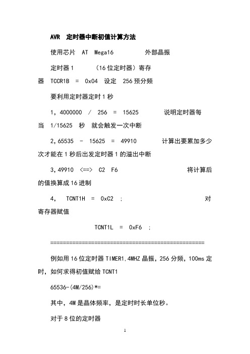
AVR 定时器中断初值计算方法使用芯片AT Mega16 外部晶振定时器1 (16位定时器)寄存器TCCR1B = 0x04 设定256预分频要利用定时器定时1秒1,4000000 / 256 = 15625 说明定时器每当1/15625 秒就会触发一次中断2,65535 - 15625 = 49910 计算出要累加多少次才能在1秒后出发定时器1的溢出中断3,49910 <==> C2 F6 将计算后的值换算成16进制4,TCNT1H = 0xC2 ; 对寄存器赋值TCNT1L = 0xF6 ;=================================================例如用16位定时器TIMER1,4MHZ晶振,256分频,100ms定时,如何求得初值赋给TCNT165536-(4M/256)*=其中,4M是晶体频率,是定时时长单位秒。
对于8位的定时器T=(2^8-计数初值)*晶振周期*分频数=(2^8-计数初值)/晶振频率*分频数计数初值=2^8-T/晶振周期/分频数=2^8-T*晶振频率/分频数因为AVR一指令一周期IAR For AVR 精确延时C语言中,想使用精确的延时程序并不容易。
IAR 中有这样的一个函数__delay_cycles(),该函数在头文件中定义,函数的作用就是延时N个指令周期。
根据这个函数就可以实现精确的延时函数了(但不能做到100%精确度)。
实现的方法:建立一个的头文件:#ifndef __IAR_DELAY_H#define __IAR_DELAY_H#include <>#define XTAL 8 //可定义为你所用的晶振频率(单位Mhz)#define delay_us(x) __delay_cycles ( (unsigned long)(x * XTAL) )#define delay_ms(x) __delay_cycles ( (unsigned long)(x * XTAL*1000) )#define delay_s(x) __delay_cycles ( (unsigned long)(x * XTAL*1000000) )#endif注意:__delay_cycles(x),x必须是常量或则是常量表达式,如果是变量则编译报错!关于溢出中断不管是哪个单片机都是不断累加,使其寄存器溢出触发中断,然后跳转到中断函数处执行中断服务程序。
AVRGCC延迟小解

AVRGCC延迟小解AVRGCC包含了很多的库函数,现对延迟函数剖析。
调用延迟函数有两个先决条件:1 必须设置晶振值,这个不需要多说;2:设置优化等级,这个下面会解释。
函数_delay_us()和_delay_ms()是对微秒级和毫秒级的延迟,_delay_us()最多延迟768us(晶振1M),_delay_ms()最多延迟262ms(晶振1M)也许很多人不明白为什么_delay_us()函数最大只能延迟768us。
其实我们查看delay的头文件很快就会明白。
The maximal possible delay is 768 us / F_CPU in MHz. If the user requests a delay greater than the maximal possible one, _delay_us() will automatically call _delay_ms() instead. The user will not be informed about this case.以上是文件中对_delay_us()函数的注释,大意是在1M晶振条件下,延迟最大可达768us;如果我们吵过这个延迟就会自动调用_delay_ms()这个函数。
以下是具体的函数:void _delay_us(double __us) {uint8_t __ticks;double __tmp = ((F_CPU) / 3e6) * __us; //微秒位单位3000000if (__tmp < 1.0) __ticks = 1;else if (__tmp > 255){_delay_ms(__us / 1000.0); //当吵过最大延迟数时,调用_delay_ms()return;}else__ticks = (uint8_t)__tmp;_delay_loop_1(__ticks); //_delay_loop_1()延迟3us*_ticks 下面分析}查看上面程序就可以得到为什么_delay_us()最大延迟为768us (256*3us),具体的晶振可以自己换算。
AVR软件 延时精确计算指导(不错)

/*************************************************************************** 延时 M32 7.3728M 粗略计算 */ void Delay100us(uint8 x) { uint8 i; //4clock
for(i=147;x!=0;x--) while(--i); //5 * i clock
在运行到第一个中断的时候 stop watch 的值是 6.68,当运行到第二个中断的时候,stop watch 的值为 148.11,可以得到 delay(254) 这条语句的执行时间约为 148.11—6.86=141.25us。我们看到软件仿真的时钟周期是 1028 个,与上面计算的 1020 个有一定差距,因为 上面的计算我们忽略了调用程序所花的时间。
void main(void) { init_devices(); delay(254);/*计算结果,本条语句延时约 138 微秒,avr studio 仿真结果延时 141 微妙,以仿真的为 准。*/
while(1) ; }
正常编译,按照常规方法打开 JTAG 下载并进入调试。我们要想办法获取程序的运行指令个数。 按下图操作调出汇编程序框:
我们由此得到语句的条数是 3+3*(n+1),这里是 3+254*(3+1)=1020 条。在普通的计算中,我们可以这样认为,for 循环的语句 数量是 n*4+4。 AVR 多数指令的执行时间是晶振频率分之一,也就是一个时钟周期,部分指令的时钟周期是 2-4 个时钟周期,详细内容请查看数据 手册。那么 delay(254);的总运行时间 1020 个时钟周期,即为 1020/(7.3728×1000000)秒,约和 1020/7.3728 =138 微秒。在要求不 高的延时中,就可以使用 for 循环来多次调用这个 delay 作为 100 微秒使用,而不用考虑外层 for 循环造成的时钟周期延时。 结语:这里只是给出了一个软件延时的简单例子,并不具有很强的使用性,实际操作中可以定义 delay100us,delay1ms,delay1s 等函数直接使用。
延时程序计算公式
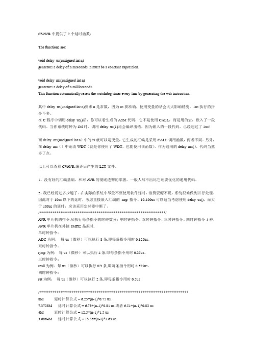
CV A VR中提供了2个延时函数:The functions are:void delay_us(unsigned int n)generates a delay of n mseconds. n must be a constant expression.void delay_ms(unsigned int n)generates a delay of n milliseconds.This function automatically resets the watchdog timer every 1ms by generating the wdr instruction.其中delay_us(unsigned int n)要求n是常数,因为us要准确,使用变量的话会大大影响精度。
1us执行的指令不多。
在C程序中调用delay_us()后,你可以看生成的ASM代码,它不是使用CALL,而是用的宏,嵌入了一段代码。
当你系统时钟为1M时,调用delay_us(1)还会编译出错,因为嵌入的一段代码,已经超过了1us!而delay_ms(unsigned int n)中的N就可以是变量,它生成的汇编是采用CALL调用函数,两者不同。
另外,在delay_ms()中还清WDT(就是你使用了WDT,也能使用该函数)。
作为通用的delay_ms(),代码当然多了点。
以上可以查看CV A VR编译后产生的LST文件。
1。
没有好的汇编基础,和对A VR的彻底透彻的掌握,一般人写不出比它还要优化的通用代码。
2。
我已经说过多少遍了。
在实际的系统中尽量不要使用软件延时,浪费资源不说,系统很难做到并行处理。
因此对于10us以下的延时,考虑直接嵌入汇编的_nop_指令。
10-100us可以适当考虑使用delay_us(),而大于100us的延时,应该采用定时器中断了。
/******************************************************************/A VR单片机的指令,从执行每条指令的时钟数分:单时钟指令、双时钟指令、三时钟指令、四时钟指令4种,A VR单片机在外接8MHZ晶振时,单时钟指令:ADC为例,每us(微秒)可以执行8条,即每条指令用时0.125us。
AVR 软件延时宏(汇编)

.IF (@0==9)
RCALL DL_9
.ENDIF
.IF (@0==10)
RCALL DL_10
.ENDIF
.IF (@0==11)
RCALL DL_11
.ENDIF
.IF (@0==12)
RCALL DL_12
.ENDIF
.IF (@0==13)
;0B01000001-8T 1+5
;0B01111111-194 5+63*3
.MACRO DL6_194
; DL194: ;(10--+3),(11--+3),(00--+4),(01--+5)
SBRC @0,7
RJMP pc+3
SBRC @0,6
RJMP PC+1
.IF (@0==32)
RCALL DL_32
.ENDIF
.IF (@0==33)
RCALL DL_33
.ENDIF
.IF (@0==34)
RCALL DL_34
.ENDIF
.IF (@0==35)
RCALL DL_35
.ENDIF
.IF (@0>35)
LDI DL_TEMP,((@0-7)/3)
;======================================================================
;======================================================================
;DL0 (0<@0≤767);@0=0不操作;仅当@0>5使用TEMP0
AVR单片机常用的延时函数
AVR单片机常用的延时函数/******************************************************************** *******///C header files:Delay function for AVR//MCU:ATmega8 or 16 or 32//Version: 1.0beta//The author:/******************************************************************** *******/#include<AVRdef.h>void delay8RC_us(unsigned int time) //8Mhz内部RC震荡延时Xus{do{time--;}while(time>1);}void delay8RC_ms(unsigned int time) //8Mhz内部RC震荡延时Xms{while(time!=0){delay8RC_us(1000);time--;}}/******************************************************************** **********/void delay1M_1ms(void) //1Mhz延时1ms{unsigned char a,b,c;for(c=1;c>0;c--)for(b=142;b>0;b--)for(a=2;a>0;a--);}void delay1M_xms(unsigned int x) //1Mhz延时xms{unsigned int i;for(i=0;i<x;i++){delay1M_1ms();}/******************************************************************** **********/void delay2M_1ms(void) //2Mhz延时1ms{unsigned char a,b;for(b=4;b>0;b--)for(a=248;a>0;a--);NOP();}void delay2M_xms(unsigned int x) //2Mhz延时xms{unsigned int i;for(i=0;i<x;i++){delay2M_1ms();}}/******************************************************************** **********/void delay4M_1ms(void) //4Mhz延时1ms{unsigned char a,b,c;for(c=7;c>0;c--)for(b=8;b>0;b--)for(a=34;a>0;a--);}void delay4M_1us(void) //4Mhz延时1us{NOP();NOP();}void delay4M_xms(unsigned int x) //4Mhz延时xms{unsigned int i;for(i=0;i<x;i++){delay4M_1ms();}/******************************************************************** **********/void delay73782M_1us(void) //7.3782Mhz延时1us{unsigned char a;for(a=2;a>0;a--);}void delay73782M_1ms(void) //7.3782Mhz延时1ms{unsigned char a,b,c;for(c=1;c>0;c--)for(b=254;b>0;b--)for(a=13;a>0;a--);}void delay73782M_xms(unsigned int x) //7.3782Mhz延时xms{unsigned int i;for(i=0;i<x;i++){delay73782M_1ms();}}/******************************************************************** **********/void delay8M_1ms(void) //8Mhz延时1ms{unsigned char a,b,c;for(c=11;c>0;c--)for(b=4;b>0;b--)for(a=89;a>0;a--);}void delay8M_1us(void) //8Mhz延时1us{unsigned char a,b;for(b=1;b>0;b--)for(a=1;a>0;a--);}/******************************************************************************/void delay12M_1us(void) //12Mhz延时1us{unsigned char a,b;for(b=1;b>0;b--)for(a=3;a>0;a--);}void delay12M_1ms(void) //12Mhz延时1ms{unsigned char a,b;for(b=129;b>0;b--)for(a=45;a>0;a--);}void delay12M_xms(unsigned int x) //12Mhz延时xms{unsigned int i;for(i=0;i<x;i++){delay12M_1ms();}}/******************************************************************** **********/void delay16M_1us(void) //16Mhz延时1us{unsigned char a,b;for(b=1;b>0;b--)for(a=5;a>0;a--);}void delay16M_1ms(void) //16Mhz延时1ms{unsigned char a,b,c;for(c=17;c>0;c--)for(b=134;b>0;b--)for(a=2;a>0;a--);}void delay16M_xms(unsigned int x) //16Mhz延时xms{unsigned int i;for(i=0;i<x;i++){delay16M_1ms(); }}。
AVR延时函数不同频率最大值
很多刚学习AVR的同学对于延时函数的使用可能不是很清楚,AVR 的延时和外接晶振密切相关,而外接晶振需要设置熔丝位,关于熔丝位的设置请见我上传的另一篇文章《SLISP的使用以及熔丝位设置》,在不了解熔丝位的情况下切勿自行设置熔丝位,否则后悔莫及。
不同频率下有不同的最大取值,我测试过8M晶振的AVR,超过32的数值一律按照32计算。
其他的没测试,具体不详,应该是这么回事。
GCC中delay_ms,delay_us延时函数在不同工作频(常用)下的最大值如下:
_delay_ms(double __ms)
The maximal possible delay is 262.14 ms / F_CPU in MHz.
工作频率最大延时值(ms)
20M 13ms
16M 16ms
12M 21ms
11.0592M 23ms
8M 32ms
7.3728M 35ms
4M 65ms
2M 131ms
1M 262ms
_delay_us(double __us)
The maximal possible delay is 768 us / F_CPU in MHz.
工作频率最大延时值(us) 20M 38us
16M 48us
12M 64us
11.0592M 69us
8M 96us
7.3728M 104us 4M 192us
2M 384us
1M 768us。
AVR延时函数
AVR的精确延时程序(2009-12-28 06:41:30)标签:avr延时杂谈分类:技术1.毫秒级的延时延时1ms;void delay_1ms(void){unsigned int i;for(i=1;i<(unsigned int)(xtal*143-2_;i++);}在上式中,xtal为晶振频率,单位为MHz.当晶振频率为8M时,延时函数软件仿真的结果为1000.25μs.当晶振频率为4M时,延时函数软件仿真结果为999.5μs.如果需要准确的1ms延时时间,则本计算公式只供参考,应通过软件仿真后,再确定循环的次数及循环初值,并且循环中还必须关闭全局中断,防止中断影响延时函数的延时时间。
下面的函数可以获得1ms的整数倍的延时时间:void delay(unsigned int n){unsigned int i;for(i=0;i<n;i++)delay_1ms();}如果需要准确的延时时间,则本计算公式只供参考,应通过软件仿真后,再确定循环的次数及循环初值.2.微秒延时晶振频率为8MHz时1μs延时函数:void delay_1us(void){asm("nop");}当然也可以使用宏定义来实现1μs延时:#define delay_1us();asm("nop");asm("nop");asm("nop");asm("nop");asm("nop");asm("nop");asm("nop");asm("nop")如果小于1μs的延时,只有使用宏定义实现,当然,也可以直接插入在线汇编asm("nop");语句实现延时。
在程序中需要微秒级的延时时,可以用以下函数实现。
void delay_us(unsigned int n){unsigned int i;for(i=0;i<n;i++)delay_1us();}说明:如果需要准确的延时时间,则还必须关中断,并通过软件仿真后,再确定循环的次数及循环初值.强调:在实际应用中一般不直接使用软件进行长时间的延时,因为MCU一直停留延时函数中(称为阻断),不能再干其它的事睛(除了中断外),只有非常简单的应用或者简单的演示时才能使用延时函数实现长时间延时。
IAR使用时报错处理与AVR精确延时
IAR使用时报错处理与AVR精确延时一、出现“IAR AVR unknown or ambiguous symbol.main”project==>;options==>;linker,format设置成debug。
IAR下必须进入DEBUG模式才能进行调试,如果不连接开发工具的话,断点也是不行的二、处于调试状态,但是不能在C语言上单步运行,也不能设置断点project==>;options==>;C/C++Compiler,将Generate debug information打上勾。
三、IAR For AVR软件的精确延时好了,废话不多说,不浪费中断的情况下的精确延时啊~~,当然是软件自带的单周期的空操作了~~,你懂得为什么,比如_nop_();(当然这个家伙是51单片机中用到的c程序,汇编就是nop;喽)在IAR for AVR中的库函数#include"intrinsics.h"里面有个单周期的延时函数__delay_cycles();(相当于_nop_();),如果__delay_cycles(100)就是100个mclk的周期延时。
然后就是下面的操作了:1)建立一个.h文件,用Keilc51这个是必须懂得,我就不多解释了2)输入代码:#ifndef __delay_h#define __delay_h#include"intrinsics.h"#define xtal 8 //这里就是你要使用的晶振的频率(单位NHZ)#define delay_us(x) __delay_cycles((unsigned long)(x*xtal))#define delay_ms(x) __delay_cycles((unsigned long)(x*xtal*1000))#define delay_s(x) __delay_cycles((unsignedlong)(x*xtal*1000000))#endif3)就是在你用到延时的函数里面调用#include"Delay.h"(这里是不区分大小写的,哈,不用担心这个)这就在不浪费中断情况下的软件延时,当然你要非得精确,那非得定时计数器不可了补充一下:我用的是IAR for AVR,别的软件什么的似乎也有延时函数,如果没有可以用下面的这个延时(听说也是相当准的,在8MHZ晶振下,不管是外接还是内部晶振,哈都一样)://------------------------------------------------------------------------------//延时函数void delay_ms(uint k){uint i,j;for(i=0;ifor(j=0;j<1140;j++);}还有一个:差点忘记(这个不知道是那个哥们想到的,也可以改变晶振的~~~都贴出来,反正没事干)://------------------------------------------------------------------------------//延时1ms的函数,没有参数传递void delay_1ms(){uint i;for(i=1;i<(uint)(xtal*143-2);i++);}//------------------------------------------------------------------------------//延时nms的函数,有参数传递void delay_nms(uint n){uint i=0;while(i{delay_1ms();i++;}}。
- 1、下载文档前请自行甄别文档内容的完整性,平台不提供额外的编辑、内容补充、找答案等附加服务。
- 2、"仅部分预览"的文档,不可在线预览部分如存在完整性等问题,可反馈申请退款(可完整预览的文档不适用该条件!)。
- 3、如文档侵犯您的权益,请联系客服反馈,我们会尽快为您处理(人工客服工作时间:9:00-18:30)。
更正。
m <= 6
/***************************************************
软件准确仿真延时时间 使用AVRstudio软件仿真可以看到准确的程序运行的时间,设置中 断的方式就可以了解到。 调入AVR Studio,为观察延时时间,点击左侧Workspace中的 Processer,注意看其中的几个参数:Cycle Counter和Stop Watch,前 一个是执行周期数,即从复位开始到目前为止共执行了多少个周期,而 Stop Watch则表示从复位开始到目前为止共用去的时间数,如果 Frenance中的频率值正确,那么这个时间就是正确的。这样,我们可 以通过观察这个时间来调循环次数,将时间基本精确地调整到延时 1ms。
我们由此得到语句的条数是3+3*(n+1),这里是3+254*(3+1)= 1020条。在普通的计算中,我们可以这样认为,for循环的语句数量是 n*4+4。 AVR多数指令的执行时间是晶振频率分之一,也就是一个时钟周 期,部分指令的时钟周期是2-4个时钟周期,详细内容请查看数据手 册。那么delay(254);的总运行时间1020个时钟周期,即为1020/ (7.3728×1000000)秒,约和1020/7.3728 =138微秒。在要求不高的 延时中,就可以使用for循环来多次调用这个delay作为100微秒使用, 而不用考虑外层for循环造成的时钟周期延时。 结语:这里只是给出了一个软件延时的简单例子,并不具有很强的 使用性,实际操作中可以定义delay100us,delay1ms,delay1s等函数 直接使用。
正常编译,按照常规方法打开JTAG下载并进入调试。我们要想办法 获取程序的运行指令个数。 按下图操作调出汇编程序框:
打开watch窗口,找到delay(254);,使用常规调试方法F10,F11, 使当前光标指向delay(254);的下一行,如下图:
使用F11逐条语句执行,你会看到如下图的运行规律,按照 1234567的方向运动,最后循环,这就是我们想要找的执行语句条数, 同时注意观察watch窗口的数值变化。通过更改watch窗口的数值,使 循 watch的值是6.68,当运行到第二 个中断的时候,stop watch的值为148.11,可以得到delay(254)这条语 句的执行时间约为148.11—6.86=141.25us。我们看到软件仿真的时钟 周期是1028个,与上面计算的1020个有一定差距,因为上面的计算我 们忽略了调用程序所花的时间。 由于笔者技术有限,错漏之处在所难免,还望高手指点,以期我们
AVR使用范例--AVR软件延时精确计算指导
和软件延时时间长短有关的因素有,单片机,晶振,延时语句,此 处以for循环语句为例。 首先,我们编写一个for循环的延时语句,如下:非关键代码省略, 点击查看全部代码。
void delay(unsigned char n) { for(;n!=0;n--) ; } void main(void) { init_devices(); delay(254);/*计算结果,本条语句延时约138微 秒,avr studio仿真结果延时141微妙,以仿真的 为准。*/ while(1) ; }
/*************************************************** 延时 M32 7.3728M 粗略计算 */
void Delay100us(uint8 x) { uint8 i; //4clock for(i=147;x!=0;x--) while(--i); //5 * i clock } void Delay1ms(uint16 n) { for (;n!=0;n--){ Delay100us(10); } } void Delay1s(uint16 m) // ,when m==7, it is 1. { m=m*40; for (;m!=0;m--){ Delay100us(250); } }