使用说明书-福玛特
Furman PST-8D电源调节器使用说明书

1The PST-8DOwners ManualIntroductionThank you for purchasing the Furman Power Station-8D Power Conditioner. For over 30 years, Furman has pioneered the development of AC power products for the most demanding audio, video, and broadcast professionals. Furman’s Series Mode Protection Plus (SMP+), Linear Filtering Technology, and Digital-HD Television Ready circuitry delivers the purest AC power and the most comprehensive protection available – going far beyond what is found in both traditional and multi-stage-filter AC power strips.Today’s power grid typically experiences numerous electrical surges and spikes on a daily basis. At best, these irregularities can degrade your equipment’s performance; at worst, they can severely damage individual components or your entire system. Not so with Furman.With our exclusive Maintenance-Free SMP+ circuitry and automatic over-voltage shutdown, the Power Station-8D assures years of trouble free service with no damaged components, no service calls, and no down time.Safety InformationTo obtain best results from your Furman Power Station-8D Power Conditioner, please be sure to read this manual carefully before using.WarningTo reduce the risk of electrical shock, do not expose this equipment to rain or moisture. Dangerous high voltages are present inside the2enclosure. Do not remove the covers. There are no user serviceable parts inside. Refer servicing to qualified personnel only.Important Safety Instructions1. Please read and observe all safety and operating instructions before installing your Power Station-8D (PST-8D). Retain these instructions for future reference.2. Your PST-8D should not be used near water – for example, neara bathtub, washbowl, kitchen sink, laundry tub, in a wet basement, near a swimming pool, etc.3. Do not place your PST-8D near heat sources such as radiators, heat registers, stoves or other appliances that produce heat.4. The PST-8D should only be connected to a 120 VAC, 60Hz, 15 amp grounded electrical outlet. Do not defeat the ground or change polarization of the power plug.5. Route the power cord and other cables so that they are not likely to be walked on, tripped over, or stressed. Pay particular attention to the condition of the cords and cables at the plugs, and the point where they exit your PST-8D. To prevent risk of fire or injury, damaged cords and cables should be replaced immediately.6. Clean your PST-8D with a damp cloth only. Do not use solvents or abrasive cleaners. Never pour liquid on or into the unit.37. Your PST-8D should be serviced by qualified service personnelwhen:• The power supply cord or the plug has been frayed, kinked, or cut.• Objects have fallen or liquid has spilled into the unit.• The unit has been exposed to rain or other moisture.• The unit does not appear to operate normally, exhibits a marked change in performance, or the Protection OK indicator is not lit.• The unit has been dropped, or the enclosure damaged.8. Your PST-8D requires that a safety ground be present for properoperation. Any attempt to operate the unit without a safety ground is considered improper operation and could invalidate the warranty.OperationAC, Telephone, and Coaxial ConnectorsDigital – Video Outlets:All (8) AC outlets feature Furman’s exclusive Linear Filtering Technology, and will noticeably improve audio and video performance by dramatically lowering incoming AC noise.However, many video and digital processing components can actually induce noise into adjacent circuits since all of the system’s components are joined at the power strip’s AC outlets. The PST-8D employs additional ultra-sonic filtering for both digital and 4video components. This additional filtering assures peak system performance by preventing AC noise or back-wash from cross-contaminating an adjacent unit. For example, a television plugged into the digital – video filtered outlets will not affect an audio receiver-controller connected to one of the PST-8D’s standard or delayed outlets.Telco – Satellite – Cable Transient Voltage Surge Suppressors: The PST-8D features transient voltage surge suppression for both standard telephone lines, as well as cable and satellite lines utilizing standard coaxial connectors. As these surge suppressors are in-line, they will require an additional cable to connect from their output to the control device requiring protection.All in-line surge suppressors feature our exclusive ground contamination free technology. This aids in eliminating audio buzzing, and the video hum-bars that can result from typical in-line suppressors. Further, our cable and satellite suppressors are TIVO friendly as well as HD-Digital Television ready. Both DC carrier signals as well as high bandwidth signals can pass through our circuit. In fact the bandwidth is less than 0.1dB loss at 1GHz!To connect your cabling to these in-line protectors, simply follow thein and out indications marked next to the Telco, Cable and Satellite connectors.Note:It is not possible to make an in-line cable or satellite protector5“maintenance-free” as we have accomplished with the 120 VAC line. This would necessitate limited signal bandwidth that would not allow the signal to pass. Under extreme conditions, it is possible that the surge suppression in one of these devices could sacrifice itself after a catastrophic event. If the telephone, cable or satellite signal will no longer pass through our protector, please send your Power Station to Furman for servicing. To test this, simply disconnect the incoming and out going cable from the PST-8D. Connect the incoming connector to the component that formerly received the out going connector, thus by-passing the in-line protection. If the signal is present (but not when used with the PST-8D’s) then the protection circuit is damaged (assuming it worked properly before the storm or catastrophic event).Circuit BreakerIf the PST-8D is connected to an AC outlet where sufficient voltage is present, the unit should operate properly with the protection OK indicator lit, after the main power switch is turned to the on position.If the unit still does not function under these conditions check the circuit breaker button! It is the round black button adjacent to the incoming AC cord. If the circuit breaker trips immediately, there may be too great of a current load placed upon it. Simply disconnect one product at a time until this no longer happens. If the breaker trips with no components connected, there may be a wiring defect that requires Furman service.IndicatorsExtreme Voltage Shutdown Indicator6Furman’s SMP+ circuit senses sustained voltages that are high enough to cause damage to your components, and shuts the power down before damage can occur. Such conditions can include accidental connection to a 240VAC source (where 120VAC is expected), or an open neutral from a 208 or 240VAC source.The Extreme Voltage Shutdown LED is normally off. If an input voltage in excess of 137VAC is sensed, either on initial power-up or during normal operation, the PST-8D will shut off power and this indicator will light.NOTE: If the mains power is above the high cutoff voltage and has caused the unit to remove power from its outlets, it can not restore power without the operator manually turning the unit off then on again. Avoid turning the unit back on without first checking the source of the problem, and perhaps changing the AC source.Protection OK IndicatorAlthough the Furman SMP+ circuit assures virtually maintenance-free protection from transient voltage spikes and surges, nature has a way of occasionally creating electrical forces that are beyond the capabilities of any transient voltage surge suppressor device to absorb without some degree of damage. In the rare instance that this occurs, the blue “Protection OK” LED indicator will turn off. If this happens, some level of protection from voltage surges will remain, but Furman’s clamping voltage rating will be compromised. The unit must be returned to Furman Sound, or an authorized Furman Service Center for repair.7MountingIf the Power Station needs to be mounted to the inside panel of a rack or hung from a wall, a convenient crossed oval cutout is provided on the unit’s bottom panel. A standard No. 6 pan head screw can be used in the same way a picture is hung from a wall. Simply measure the centers on the bottom of your Power Station. This will be the distance from the two mounting holes drilled into your wall, rack or cabinet surface. Once the screw is fastened flush with the surface, back it out approximately ½”. The screw head should push through the crossed cutout on the bottom surface of the Power Station. Next, simply allow the Power Station to move down and seat into the end of its oval cut-out. Adjust the pan head screw if necessary.WarrantyT o Register for the following warranty please visit Furman’s website at www. and click on the “warranty” page, or call Furman at (707) 763-1010.Furman Sound, Inc. warrants to the original purchaser of this product, the Furman PST-8D, that the product will be free from defects in material and workmanship fora period of three years from the date of purchase. The purchaser of the product isallowed fifteen days from the date of purchase to complete warranty registration by mail or on-line at the Furman website. If the purchaser fails to complete the aforementioned registration, the warranty period will be reduced to one year from the date of purchase.If the product does not conform to this Limited Warranty during the warranty period (as herein above specified), purchaser shall notify Furman in writing of the claimed defects. If the defects are of such type and nature as to be covered by8this warranty, Furman shall authorize the purchaser to return the product to the Furman factory or to an authorized Furman repair location. Warranty claims should be accompanied by a copy of the original purchase invoice showing the purchase date; this is not necessary if the Warranty Registration was completed either by mailing in the completed warranty card or by registering on-line at the Furman website. Shipping charges to the Furman factory or to an authorized repair location must be prepaid by the purchaser of the product. Furman shall, at its own expense, furnish a replacement product or, at Furman’s option, repair the defective product. Return shipping charges back to purchaser will be paid by Furman.CONNECTED EQUIPMENT WARRANTY: Furman Sound’s Connected Equipment Warranty covers equipment that is damaged by transient voltage (an “Occurrence”) while properly connected through the Furman PST-8D to a properly wired AC power line with a protective ground in an indoor location. Furman’s Connected Equipment Warranty is limited to the amount of the deductible on the Purchaser’s personal property insurance policy up to $500.00. In order to makea claim for this Connected Equipment Warranty, the Purchaser must forward a copy of his/her personal property insurance claim for the damaged equipment to Furman and complete the Furman Connected Equipment Warranty claim form (call Furman at (707) 763-1010 to obtain the form). Furman reserves the right to review the damaged Furman product, the damaged connected equipment, and the site where the damage occurred. All cost of shipping damaged equipmentto Furman for inspection shall be borne solely by the Purchaser. Damaged equipment must remain available for inspection until the claim is finalized. The Connected Equipment Warranty is also in effect for a period of three years unless the Purchaser does not complete the warranty registration within fifteen days from date of purchase, at which time, the Connected Equipment Warranty period is also reduced to one year from the date of purchase.9All warranties contained herein are null and void if: the Furman Surge Protector in use during the occurrence is not provided to Furman for inspection upon Furman’s request at the sole expense of the Purchaser, Furman determines that the Furman Surge Protector has been opened, improperly installed, altered in any way or tampered with, Furman determines that the damage did not result from the Occurrence or that no Occurrence in fact took place or Furman determines that the connected equipment was not used under normal operating conditions or in accordance with Manufacturer’s instructions for the connected equipment.All Furman Surge Protectors must be plugged directly into a properly wired AC power line with a protective ground and must not be “daisy-chained” together in serial fashion with other power strips, UPS’s, other surge protectors, three-to-two-prong adapters, or extension cords. Any such installation voids this warranty. The Furman warranty only protects against damage to properly connected equipment where Furman has determined, at its sole discretion, that the damage resulted from an Occurrence and does not protect against acts of God (other than lightning) such as flood, earthquake, war, terrorism, vandalism, theft, normal-use wear and tear, erosion, depletion, obsolescence, abuse, damage due to low-voltage disturbances (i.e. brownouts or sags), non-authorized program, or system equipment modification or alteration. Do not use this product in anyway with a generator, heater, sump pump, water-related device, life support device, medical device, automobile, motorcycle, or golf-cart battery charger. To be used indoors only and in dry areas. All warranties contained herein are null and void if used in anyway with any of the aforementioned devices.THE FOREGOING IS IN LIEU OF ALL OTHER WARRANTIES, EXPRESS OR IMPLIED, INCLUDING BUT NOT LIMITED TO THE IMPLIED WARRANTIES OF MERCHANTABILITY AND FITNESS FOR A PARTICULAR PURPOSE. Furman10does not warrant against damages or defects arising out of improper or abnormal use or handling of the product; against defects or damages arising from improper installation, against defects in products or components not manufactured by Furman, or against damages resulting from such non-Furman made products or components. This warranty shall be cancelable by Furman at its sole discretion if the product is modified in any way without written authorization from Furman. This warranty also does not apply to products upon which repairs have been affected or attempted by persons other than pursuant to written authorization by Furman.THIS WARRANTY IS EXCLUSIVE. The sole and exclusive obligation of Furman shall be to repair or replace the defective product in the manner and for the period provided above. Furman shall not have any other obligation with respectto this product or any part thereof, whether based on contract, tort, strict liability,or otherwise. Under no circumstances, whether based on this Limited Warrantyor otherwise, shall Furman be liable for incidental, special, or consequential damages. Furman’s employees or representatives’ ORAL OR OTHER WRITTEN STATEMENTS DO NOT CONSTITUTE WARRANTIES, shall not be relied upon by purchaser, and are not a part of the contract for sale or this limited warranty. This Limited Warranty states the entire obligation of Furman with respect to the product.If any part of this Limited Warranty is determined to be void or illegal, the remainder shall remain in full force and effect.Warranty claims should be accompanied by a copy of the original purchase invoice showing the date of purchase (if a Warranty Registration Card was mailed in at the time of purchase or if the product was registered on-line, this is not necessary). Before returning any equipment for repair, please be sure it is adequately packed and cushioned against damage in shipment, and that it is insured.11ServiceAll equipment being returned for repair must have a Return Authorization (R/A) Number. To get an R/A number, please call the Furman Service Department at (707) 763-1010 ext 121, between the hours of 8:00 am and 5:00 pm US Pacific Time. When returning equipment for repair, please use the original packaging to ship the product. Also, please enclose a note giving your name, address, phone number, e-mail address, and a description of the problem.Please display your R/A Number prominently on the front of all packages.Furman Sound, Inc.1997 South McDowell Blvd.Petaluma, California 94954-6919 USAPhone: 707-763-1010Fax: 707-763-1310Web: 12E-mail:********************110304-C。
福马特编程调试工具

电眼受到阻挡次数。
电眼故障原因主要为: • 电眼被阻碍超过两分钟(电眼计时器选项激活) • 开门初始时电眼被阻碍。
Blockage cycles
开门过程中电ycles 自学习次数。
Reopen cycles
重开门次数。
Hours
电梯工作时长。
Grid faults
Pág. 1 / 13
说明书 DOC-FE.IE.IN.014156.CE 编程工具 版本: 0.2
INDEX索引
● 产品简介......................................................................................................................................................3 ● 测试菜单......................................................................................................................................................5 ● 编程菜单......................................................................................................................................................8 ● 配置菜单.....................................................................................................................................................11 ● 参数列表.....................................................................................................................................................12
MOTEC α系列伺服使用手册v1.1
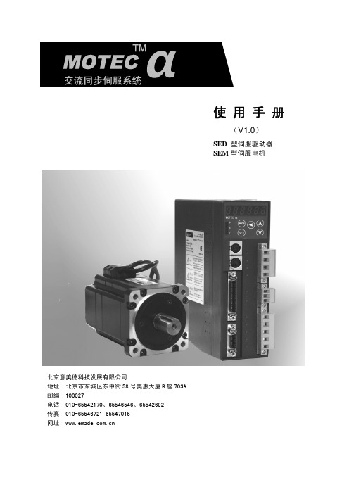
使用手册
(V1.0)
SED 型伺服驱动器 SEM 型伺服电机
北京意美德科技发展有限公司 地址: 北京市东城区东中街 58 号美惠大厦 B 座 703A 邮编: 100027 电话: 010-65542170、65546546、65542692 传真: 010-65546721 65547015 网址:
α系列伺服电机系统使用手册
章 节:
第 1 章. 伺服电机与驱动器型号 第 2 章. 安装和配线 第 3 章. 驱动器 JP2 接口(I/O 控制信号)功能说明 第 4 章. 面板操作操作说明 第 5 章. 性能调整功能说明 第 6 章. 控制模式 第 7 章. 监视项 第 8 章. 伺服驱动器工作时序图 第 9 章.驱动器 JP3/JP4(通信端口)定义、接线及通信协议 附录 1: 驱动器参数列表 附录 2:故障信息、故障原因及处理措施 附录 3:SEM 电机电气参数
1. 伺服电机与驱动器型号 ................................................................. 5 1.1 伺服电机型号定义 ................................................................. 5 1.2 伺服驱动器型号定义 ............................................................... 6 1.3 α系列驱动器与电机组合 ........................................................... 6 1.4 α系列驱动器外形及安装尺寸图 ..................................................... 8
FOSS官方资料 FT120中文操作手册
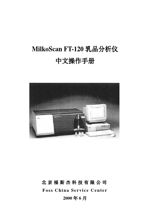
MilkoScan FT-120乳品分析仪中文操作手册北京福斯杰科技有限公司F os s C hi na Se r vi c e Ce n te r2000年6月目录第1章简介 (5)§1。
1FT—120乳品分析仪 (5)§1。
2关于这本手册 (6)§1。
3福斯电子的校准模块 (6)§1。
4FT—120仪器可选择的模块 (7)§1。
4。
1自动清洗和调零模块(ACZ) (7)§1。
4。
2 应用模块 (7)§1。
4。
3 天平选项 (7)§1。
4。
4 高级性能模块 (7)§1。
4。
5高级校准模块 (8)§1。
4。
6 输入选择模块 (8)§1。
4。
7 数据交换选择模块(DDE) (8)§1。
4。
8 品质确认模块 (8)§1。
5窗口系统 (9)§1。
5。
1 菜单栏 (9)§1。
5。
2 功能键 (10)§1。
5。
3 按钮栏 (10)§1。
5。
4 滚动栏 (10)§1。
5。
5 状态栏 (10)§1。
6定义自己的窗口 (10)§1。
7仪器语言支持 (10)§1。
7。
1 怎样使用当地语言 (11)§1。
8激光的保险装置 (11)第2章FT—120乳品分析仪用户界面 (11)§2。
1FT—120乳品分析仪插图屏幕说明 (12)§2。
2按钮板 (13)§2。
3功能键 (13)§2。
4快捷键 (14)§2。
5其它菜单 (14)§2。
6菜单概要 (15)§2。
6。
1 菜单中的基本模块 (15)§2。
6。
2 应用模块菜单 (16)§2。
7物理连接与转换 (16)第3章操作 (18)§3。
1调零和实验样品 (18)§3。
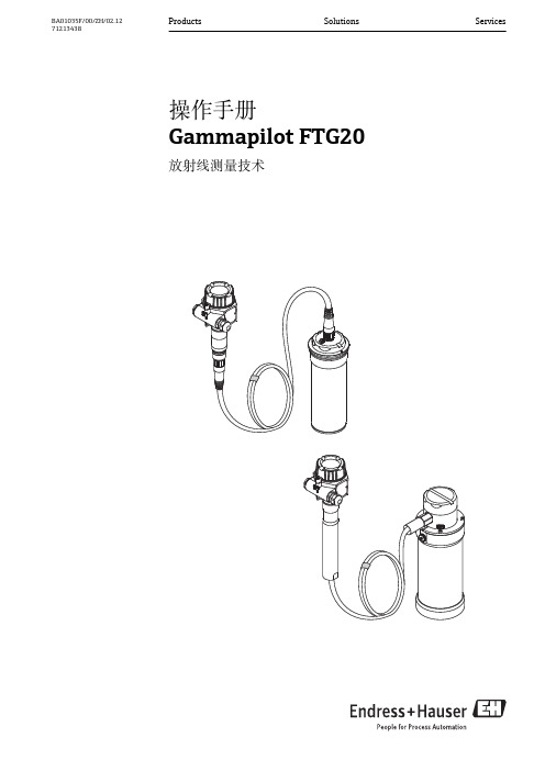
Gammapilot FTG20伽码物位开关操作手册_BA01035FZH_0212
13 14
返回 . . . . . . . . . . . . . . . . . . . . . . . . . . . . . . 48 附录 . . . . . . . . . . . . . . . . . . . . . . . . . . . . . . 49
3
3.1
产品描述 . . . . . . . . . . . . . . . . . . . . . . . . . . 10
8
8.1 8.2
操作方式 . . . . . . . . . . . . . . . . . . . . . . . . . . 31
通过现场显示访问操作菜单 . . . . . . . . . . . . . . 31 显示与操作单元 . . . . . . . . . . . . . . . . . . . . . . 31
wwwendresscom下载132文档资料操作手册放射源盒文档资料代号qg2000ba00223fqg2000美国ba00370f技术资料设备设备型号文档资料代号fqg60ti00445ffqg6162ti00435ffqg63ti00446fqg2000ba00223fqg2000美国ti00427f特殊文档资料设备设备型号文档资料代号说明qg2000sd00142f在加拿大使用的放射源和放射源盒的补充安全指南fqg60fqg61fqg62fqg63sd00292f在加拿大使用的放射源和放射源盒的补充安全指南fqg61fqg62sd00293f美国
文档信息
图标
说明 提示 标识附加信息。
A0011193
参考文档 参考相关设备文档。
A0011194
参考页面 参考相关页面。
A0011195
福马特门机简介

福马特门机系统简介
机械部分
中分门机,轿门系统的部件说明:
1.安装支架 2.门机 3.挂门板 4.门板 5.地坎 6.地坎托架 7.护脚板
轿门系统的安装
1.将安装支架与位于轿厢顶部 C 形安装槽连接. 2.确定门头板底边的安装高度比净高高 220mm. (图 1) 3.将门机固定安装在安装支架上. (图 2) 4.调节安装支架确定门头板与轿厢边缘的距离为 30mm. (图 3) 5.将安装支架固定在 C 形槽上.
子8和10之间的12-250V直流电或交流电均会使门闭,去处这一电压信号,门将打开。 当门开始关闭时,开门输入无效。 OFF: 2 Inputs. 双信号输入。由两个独立的输入信号分别控制开门和关门。任何加在端 子8和10之间的12-250V直流或交流电均会使门关闭;任何加在端子12和10之间的 12-250直流电或交流电均会使门打开。如果没有任何信号,门将保持静止不动;如 果同时有开门和关门信号输入,开门信号优先。
导靴及挂门螺栓的安装
福马特门机系统简介
门板的安装及调整
1.将门板挂到对应的挂门板上之后,移动与轿门门框边缘齐平. 2.拧紧挂门板上的挂门螺栓. 3.调节螺母使门板与门框平行,保持门板下边缘与地坎,门板与门框,门板与门板间隙为 5mm.
门板的调整
1.拆掉导靴. 2.校正门板使之与地坎平行. 3.重新安装导靴.
控制信号输入 (8, 9, 10, 11, 12) 控制器可由外部电压信号控制,也可由内部电压控制。
福马特门机系统简介
• 12. 开门信号 输入阻抗20 KOhm,电压输入12-250 V 交流或直流。 与关门信号特征相同。
• 11. 0 电压 是内部12 V (端子 9) 的一部分 . 如果输入端子9 被使用, 这个端子必须连接到 公共端子10。参见内部12V电压控制示意图。
福瑞特指纹锁说明书
福瑞特指纹锁说明书指纹锁技术与参数开锁认证方式:指纹、密码、机械钥匙、(遥控选配)指纹采集窗口:光学式指纹图像分辨率:500dpi指纹图像采集时间:<0.5s指纹对比:<1s指纹对比方式:1:N指纹误识别率(FZR):<.001%指纹拒真率(FRP): <0.1%指纹容量:3000枚密码容量:8组遥控容量30个开门记录容量3000条LED指示低压报警:<4.2V供电电压:DC6V电流消耗:峰值电流<120mA,平均电流<45mA电池:4-8节AA碱性电池功能特点1:瞬间启动——指纹门锁2:智能沟通——液晶显示3:主宾显示——分享不同权限4:智能语音提示——操作便捷5:触摸式密码设计——时尚耐用6:超B级叶片空旋锁头——应急钥匙7:电源显示外置——欠电显示8:指纹同步更新功能9:常开——办公商务方便10:指纹+密码二合一式开启——安全保障11:禁试功能——保护外侵12:挟持密码设置——人性化安全保障13:开门记录——数据记录存储查询14:防撬报警——撬锁报警锁具关闭保护15:液晶显示——时尚大气16:上提把手——上锁天地勾锁门管理指纹设置按电池盒后面“”号设置键进入菜单→∈提示“注册管理指纹”时正确放入手指提示“请在录入一次”三次录入至系统提示“录入成功”→表示录入成功,注:前五枚录入的指纹为管理指纹,系统从1-5自动按顺序记录管理指纹ID号。
录入完毕按“*”号键退出。
用户指纹设置按电池盒后面“”号设置键进入菜单→∈提示“验证管理员指纹”时扫描管理指纹进入菜单→进入“1指纹设置”栏后按“#”号键确认进入→画面显示“1添加指纹”栏按“#”号键确认→按“8”号键向下选择至用户指纹栏(第六枚及以后为用户指纹)→正确将手指放入指纹窗口三次至系统提示“录入成功”→表示录入成功,系统自动按顺序记录指纹的ID号,按“#”号键可继续录入下一枚指纹. 可以录入用户指纹2995枚,录入完毕按“*”号键退出。
密码设置按电池盒后面“”号设置键进入菜单→∈提示“验证管理员指纹”时扫描管理指纹进入菜单→按“8”号键向下选择进入“密码设置”栏→按“#”号键确认→进入“添加密码”栏后按“#”号键确认设置第“1组用户密码”→按“#”号键确认→输入要设置的密码后按“#”号键确认→重新输入您要设置的密码按“#”号键确认至“滴答滴”或“添加成功”.(注:a可设置8组用户密码,每组密码最多12位,b本锁出厂时不设置用户密码,c当您设置密码后才可以使用密码,d本锁密码为乱码设计,输入密码时前、后可随意按多位数字键以防止旁人偷窥,前、后可以各12位乱码)遥控器设置按电池盒后面“”号设置键进入菜单→∈提示“验证管理员指纹”时扫描管理指纹进入菜单→按“8”号键下调至“遥控设置”栏再按“#”号键确认进入→提示“添加遥控器”时按“#”号键确认→按住遥控器上的任意键至系统提示“添加成功”表示录入成功,系统自动按顺序记录遥控器的顺序号,按“#”号键可继续录入下一个遥控器,录入完毕等待10秒,超时自动退出。
佛玛特 MO NDW AC 安全技术说明书
安全技术说明书页: 1/10 巴斯夫安全技术说明书按照GB/T 16483编制日期 / 本次修订: 18.10.2022版本: 4.1日期/上次修订: 20.07.2022上次版本: 4.0日期 / 首次编制: 03.12.2012产品: 佛玛特 MO NDW ACProduct: Foamaster® MO NDW AC(30574221/SDS_GEN_CN/ZH)印刷日期 30.10.20231. 化学品及企业标识佛玛特 MO NDW ACFoamaster® MO NDW AC推荐用途和限制用途: 涂料工业用原料或专职人使用, 墨水,清漆或涂料用添加剂, 消去泡沫公司:巴斯夫(中国)有限公司中国上海浦东江心沙路300号邮政编码 200137电话: +86 21 20391000传真号: +86 21 20394800E-mail地址: **********************紧急联络信息:巴斯夫紧急热线中心(中国)+86 21 5861-1199巴斯夫紧急热线中心(国际):电话: +49 180 2273-112Company:BASF (China) Co., Ltd.300 Jiang Xin Sha RoadPu Dong Shanghai 200137, CHINA Telephone: +86 21 20391000Telefax number: +86 21 20394800E-mail address: ********************** Emergency information:Emergency Call Center (China):+86 21 5861-1199International emergency number: Telephone: +49 180 2273-1122. 危险性概述巴斯夫安全技术说明书日期 / 本次修订: 18.10.2022版本: 4.1产品: 佛玛特 MO NDW ACProduct: Foamaster® MO NDW AC(30574221/SDS_GEN_CN/ZH)印刷日期 30.10.2023标签要素和警示性说明:根据GHS标准,该产品不需要添加危险警示标签其它危害但是不至于归入分类:注意有关存储和操作的规定或注解,无已知特殊危害。
Furuno TATA IB-781 产品说明书
CREDIT CALL ADAPTERIB-781C9-52,A s h i h a r a-c h o,A l l r i g h t s r e s e r v e d.PUB. No. OME-56094I B-781(TATA) FI RST EDI TI ON : DEC. 1999Printed in JapanSafety Instructions for the OperatorSafety Instructions for the InstallerTABLE OF CONTENTSFOREWORD (iv)SYSTEM CONFIGURATION (v)EQUIPMENT LIST (vi)1.OPERATIONAL OVERVIEW (1)1.1Control Description (1)1.2Turning the Power On/Off (2)1.3Telephone Credit Card Call Procedure (3)1.4Fax Credit Card Call Procedure (5)1.5How to Dial PIN No (8)1.6Telephone, Fax Usage (8)2.MAINTENANCE, TROUBLESHOOTING (9)2.1Cleaning (9)2.2Replacement of Fuse (9)2.3Troubleshooting (9)3.INSTALLATION (11)3.1Mounting (11)3.2Wiring (13)3.3TEL, FAX Port Setup on FELCOM 80, FELCOM 81 (16)SPECIFICATIONS.......................................................................................................SP-1 OUTLINE DRAWING.....................................................................................................D-1 INTERCONNECTION DIAGRAM..................................................................................S-1FOREWORDFURUNO Electric Company thanks you for purchasing the FURUNO IB-781 Credit Call Adapter.The IB-781 is designed to meet the rigorous demands of the marine environment. However, no machine can perform to the utmost of its ability unless it is properly installed and maintained. Please carefully read and follow the recommended procedures for installation, operation and maintenance to get maximum performance from this equipment.FeaturesThe IB-781 Credit Call Adapter and its companion card reader connect between the TEL or FAX port on the FURUNO FELCOM 80 or FELCOM 81 Inmarsat B Mobile Earth Station and a telephone or fax to provide credit card calling by telephone or fax.The major features of the IB-781 are•Fully complies with Inmarsat B technical standards (SDM Issue 3.0).•Reads most major credit cards.• 4 (FELCOM 80) or 5 units (FELCOM 81) may be connected.•Operates independently of the card reader plugged into the TEL, FAX connector on the FELCOM 80, FELCOM 81.SYSTEM CONFIGURATIONShip's Mains 100/200 VAC,1φ, 50/60 HzSystem configuration with FELCOM 80Ship's Mains 100/200 VAC,1φ, 50/60 HzSystem configuration with FELCOM 81EQUIPMENT LIST Standard SupplyName Type Qty RemarksCredit CallAdapterIB-7811w/Card Reader MCT-1504-4, mounting baseInstallation Materials, Spare Parts – 1 setInstallation Materials1) Connection cable RS-232C (0.5 m, IB-781 ↔ Card Reader)2) Modular jack cable (2 core, 3 m, IB-781 ↔ FELCOM)3) Power cable (3 m)4) Tapping screw (4 pcs.)Spare Parts1) Fuse (1A)1. OPERATIONAL OVERVIEW 1.1Control DescriptionThe IB-781's lone control is a POWER switch, and it is located on the rear panel. LEDs on the front panel light or flash according to equipment status. The 1A fuse on the rear panel protects the equipment from overvoltage and equipment fault.RS-232C connector(Connects to CARDLights when equipment is powered.Front viewCARD READER connector(Connects to RS-232Cconnector on card reader.)Rear view1.2Turning the Power On/OffThe IB-781 checks itself and the card reader when powered on, in the following sequence.1.3Telephone Credit Card Call Procedure 1.3.1Read credit card before picking up handsetBasic procedureLES No.ServiceCode CountryCodeSubscriber No.AreaCodeEnd CodeExample: Dial Y amaguchi operator (003), Automatic call (00), Japan (81),T okyo (03), subscriber no. (1234-5678)003 - 00 - 81 - 3 - 1234 - 5678Detailed procedure1. Confirm that the LED on the card reader is lit.2. Pass credit card through the card reader. Listen for a long beep, signifying that the card wassuccessfully read. For error short beeps are emitted and the ERROR lamp lights for fiveseconds.3. Pick up the handset, listen for the dial tone (see Note 1 below) and dial number. Dial numberwhile the OK lamp is lit (about 20 seconds). Some LES require PIN No. (see paragraph 1.5). If the line is busy (beep every 0.5 seconds) hang up the handset and try again later.Note 1: Dial tone format: FELCOM 80, 0.8 sec. on, 0.2 sec. off, FELCOM 81, continuous tone.Note 2:A beep sounds every 0.5 seconds when an incoming call arrives.1.3.2Read credit card after picking up handset Basic procedureLES No.ServiceCode CodeSubscriber No.AreaCodeEnd CodeExample: Dial Y amaguchi operator (003), Automatic call (00), Japan (81),T okyo (03), subscriber no. (1234-5678)003 - 00 - 81 - 3 - 1234 - 5678Detailed procedure1. Confirm that the LED on the card reader is lit.2. Pick up the handset and listen for the dial tone (see Note 1 below). Pass the card through thecard reader within 20 seconds after picking up the handset. Confirm that a long beep sounds, signifying the card was properly read.3. Dial number while the OK lamp is lit (about 20 seconds). Some LES require PIN No. (seeparagraph 1.5). If the line is busy (beep every 0.5 seconds) hang up the handset and try again later.Note 1: Dial tone format: FELCOM 80, 0.8 sec. on, 0.2 sec. off, FELCOM 81, continuous tone. Note 2:A beep sounds every 0.5 seconds when an incoming call arrives.1.4 Fax Credit Card Call Procedure1.4.1 Read credit card without picking up handsetBasic procedureLES No.Service CodeCountryCode Subscriber No.AreaCodeEnd CodeExample: Dial Y amaguchi operator (003), Automatic call (00), Japan (81),Tokyo (03), subscriber no. (1234-5678)Detailed procedure1. Confirm that the LED on the card reader is lit.2. Set document to fax and dial number. Some LES require PIN No. (see paragraph 1.5).3. Pass card through card reader. Listen for long beep, signifying the card was properly read.Several beeps sound and the ERROR lamp lights for five seconds in case of error.4. Push start button on fax.1.4.2 Read card before picking up handsetBasic procedureLES No.Service CodeCode Subscriber No.AreaCodeEnd CodeExample: Dial Y amaguchi operator (003), Automatic call (00), Japan (81),T okyo (03), subscriber no. (1234-5678)003 - 00 - 81 - 3 - 1234 - 5678Detailed procedure1. Confirm that the LED on the card reader is lit.2. Pass credit card through card reader. Listen for long been, signifying the card was properlyread. Several beeps sound and the ERROR lamp lights for five seconds in case of error.3. Set document to fax.4. Pick up handset, listen for dial tone (see Note 1 below) and dial number. Some LES requirePIN No. (see paragraph 1.5). Dial number while the OK lamp is lit (about 20 seconds).5. Push start button on fax when you hear the fax tone.Note 1: Dial tone format: FELCOM 80, 0.8 sec. on, 0.2 sec. off, FELCOM 81, continuous tone.Note 2:A beep sounds every 0.5 seconds when an incoming call arrives.1.4.3 Read credit card after picking up faxBasic procedureCode Code CodeExample: Dial Y amaguchi operator (003), Automatic call (00), Japan (81),T okyo (03), subscriber no. (1234-5678)Detailed procedure1. Confirm that the LED on the card reader is lit.2. Set the document to the fax, pick up the handset and listen for the dial tone (see Note 1 below)and pass the credit card through the card reader within 20 seconds of hearing the dial tone.Listen for a long beep, signifying the card was properly read. If the line is busy (beep every 0.5 seconds) hang up the handset and try again later.3. Dial number while the OK lamp is lit (about 20 seconds). Some LES require PIN No. (seeparagraph 1.5).4. Listen for fax tone and then press the START button on your fax.Note 1: Dial tone format: FELCOM 80, 0.8 sec. on, 0.2 sec. off, FELCOM 81, continuous tone. Note 2:A beep sounds every 0.5 seconds when an incoming call arrives.1.5 How to Dial PIN No. Dial PIN No. as below.Area Code CountryCodeSubscriber No.AreaCodeEndCodePIN No.1.6Telephone, Fax UsageTelephone or fax may be used as usual when the credit card reader connected to the telephone or fax is not in use.2. MAINTENANCE, TROUBLESHOOTING2.1CleaningDust or dirt can be removed from the equipment with a soft cloth. Do not use commercial cleaners to clean the equipment – they can remove paint and markings.Cleaning of card readerClean the card reader slot regularly with the cleaning card (supplied).2.2Replacement of FuseThe 1A fuse on the rear panel protects the equipment from overvoltage and equipment fault. If the fuse blows find out the cause before replacing it.2.3 Troubleshooting2.3.1When a card cannot be readIf a credit card cannot be read try the following:•Check if the IB-781 is powered. (The POWER LED should be ON.)•Turn off the IB-781 and check the connection between it and the card reader.•Check the magnetic strip on the card for damage and foreign material.•Use the cleaning card (supplied) to clean the card reader head.2.3.2Troubleshooting by LED, BuzzerAdapter LED Status Card ReaderOK ER LED BuzzerProblem OFF OFF ON---None (normalON OFF ON Long Card properly read OFF ON *1ON or OFF *2---Card readerconnection problem OFF Lights five sec.ON Three short beeps Card not properlypassed.Flashing *3Flashing *3ON Three short beeps,twice Card read is not a credit cardOFF Flashing(2 sec. int., 3 times)ON Three short beeps,twiceParity, check sumerrorFlashing with ER *4Flashing with OK *4ON or OFF *5---Self test error (atpower on)*1: 0.5 seconds on, 0.5 seconds off.*2: “LED OFF command” is sent to card reader, but may not be processed since the equipment is not properly connected.*3: OK LED and ER LED flash and light alternately five times, respectively, starting with ER, and then bothgo off.*4: Flashing continues until power is turned off.*5: “LED control command” is not output to the card reader so previous LED status is maintained. Note: Do not use the IB-781 when the self test shows error. Contact an FURUNO agent for service.3. INSTALLATION3.1Mounting3.1.1Mounting considerationsThe IB-781 can be mounted on a desktop or on a bulkhead. When selecting a mounting location consider the following points:•Leave sufficient space around the equipment for operating, maintenance and checking ease.(It is especially important to leave sufficient space at the rear of the unit to allow access to the POWER switch and fuse.) See the outline drawing at the back of this manual for minimum recommended clearances.•Locate the equipment out of direct sunlight because of heat that can build up inside the cabinet.•Mount the equipment near the telephone or fax it is to be used with.•The mounting location should be moderate and stable in both temperature and humidity.•Keep the equipment away from areas subject to rain and water splash.3.1.2Mounting procedureFasten the IB-781 to the mounting location with four tapping screws (supplied).Fixing Hole φ4.63.2Wiring3.2.1Standard wiring FELCOM 80LINETEL/FAX CARD READER Connect to groundT o CARD READERRS-232C Cable (supplied)T o AC Outlet (Power cable supplied)T o LINE T o TEL/FAXTELEPHONEFAXJUNCTION BOX IB-311M o d u l a r J a c k C a b l e (s u p p l i e d )T o TB1Ground the equipment toprevent electrical shock andmutual interference.CAUTIONDC IN RS-232CFELCOM 81LINETEL/FAX CARD READER POWERT o CARD READERRS-232C Cable (supplied)T o AC Outletsupplied)T o LINET o TEL/FAX TELEPHONEFAXT o appropriateTEL port (exceptTEL1). Use TEL5 orTEL6 for Fax.M o d u l a r J a c k C a b l e (s u p p l i e d )DC IN RS-232C3.2.2Multiple unit installation examplesBelow are examples of multiple installations of the IB-781. In the examples, TEL2, TEL3 and FAX1 are connected to the IB-781 on the FELCOM 80, and TEL2, TEL3 and TEL5 (TEL5 is set for fax use) are connected to the IB-781 on the FELCOM 81.Note: IB-781 cannot be connected to TEL1 or FAX 1 port.Connection of multiple IB-781 to the FELCOM 80Note: IB-781 cannot be connected to TEL1 port.Connection of multiple IB-781 to the FELCOM 813.3TEL, FAX Port Setup on FELCOM 80, FELCOM 81 Set the TEL, FAX ports on the FELCOM 80 ( FELCOM 81) as follows:1. Pick up the handset of the No. 1 telephone and dial *, 9, 4, A, B, #, where A is Port No. and Bis Mode.A: Port No.2: TEL23: TEL34: TEL45:TEL5 (FELCOM 81)6: FAX2 (FELCOM 80), TEL6 (FELCOM 81)B: Mode0: No credit card adapter connected (default setting)4: Credit card call adapter connectedFor example, If the credit card adapter is connected to TEL2, dial9424*#2. Hang up the handset.3. Repeat this procedure to set other telephones and faxes.Note: Credit card adapter cannot be connected to TEL1. Further, on FELCOM 80, FAX1 cannot be used to connect the credit card adapter.SPECIFICATIONS OF CREDIT CARD ADAPTORIB-7811. GENERAL(1) Port Number Line port (2 way modular jack): 1Telephone/facsimile port (2 way modular jack): 1(2) Useable Card International credit card or KDD card(3) LED indication POWER/ OK/ ERROR2. POWER SUPPLY(1) Main Unit 100-220 VAC (±10%): 70 mA or less, 50-60 Hz (±5%)(2) Fuse 1 A3. ENVIRONMENTAL CONDITION(1) Ambient Temperature -15°C to +55°C (IEC60945)(2) Relative Humidity 95% at 40°C(3) Vibration ±1.6 mm ±10%, 5 to 12.5 Hz,Maximum acceleration 9.8 m/s2±10%, 12.5 to 100 Hz (IEC60945) (4) Waterproofing IPX04. COATING COLOR(1) Main Unit Chassis: 2.5GY5/1.5, Panel: N3.0。
福玛特 T9 擦窗机器人 使用说明书
注:本表格依据SJ/T11364的规则编制
电池位置
部件名称
上盖 下盖 轮子组件 电源线 锂电池 马达 PCB 金属件 包装及其他
铅(Pb)
汞(Hg) 镉(Cd)
有害物质
六价铬(Cr(VI))
多溴联苯(PBB) 多溴二苯醚(PBDE)
X
: 表示该有害物质在该部件所有均质材料中的含量均在GB/T26572(IEC62321)规定的限量要求以下
X : 表示该有害物质至少在该部件的某一均质材料中的含量超出GB/T26572规定的限量要求。但是上表中“x”的部件表示其含量超出是因为向右旋转
1.将DC延长线接上适配器; 2.将AC电源线接上适配器; 3.将L型螺纹插头插入机身电源接口并旋紧; 4.将电源线插入插座。
1.将机器贴于玻璃上,按下启动键机器向上再向左到达玻璃左上角位置; 2.机器以弓字型路径从上向下清洁; 3.清洁结束后机器停止运行,吸附在玻璃上。
喷水键 喷一次
X2
擦两次
方向键 启停键
定向键
注: 1.为防止误操作,指令之间需要按暂停键; 2.定向键注解: ①.向左按键:从当前位置向左移动后弓字形清扫; ②.向上按键:同“路径规划×1; ③.向右按键:从当前位置向右移动后弓字形清扫; 3.喷水键注解: ①.按一下喷水关闭; ②.再按一下喷水开启; 4.使用前取出电池隔离片。
- 1、下载文档前请自行甄别文档内容的完整性,平台不提供额外的编辑、内容补充、找答案等附加服务。
- 2、"仅部分预览"的文档,不可在线预览部分如存在完整性等问题,可反馈申请退款(可完整预览的文档不适用该条件!)。
- 3、如文档侵犯您的权益,请联系客服反馈,我们会尽快为您处理(人工客服工作时间:9:00-18:30)。
使用说明书感谢您购买此产品使用前请仔细阅读说明书内容,本产品仅限中国大陆地区使用衷心感谢您选购福玛特智能扫地机!希望您使用愉快。
在使用过程中有任何问题,请您联系我们的售后服务中心:400-650-0227,将有专业人员为您解答。
本产品以实物为准,我公司保留产品更新权利,如有变动,恕不另行通知。
再次感谢您选择福玛特扫地机!目录1.安全说明 (1)2.产品组成 (2)2.1 主机及附件 (2)2.2 主机 (3)2.3 充电座 (3)2.4 尘盒 (4)2.5 水箱 (4)2.6 显示屏 (5)2.7 遥控器 (5)3.产品操作 (7)3.1 快速使用指南 (7)3.2 开机/暂停/待机 (8)3.3 预约清扫 (10)3.4 清扫模式 (10)3.5 拖布底盘操作 (11)4.产品维护 (12)4.1 左右毛刷清洁 (12)4.2 垃圾盒与滤网清洁 (12)4.3 中扫毛刷清洁 (12)4.4 传感器镜片及电极片清洁 (13)4.5 电池更换 (13)5.常见代码 (14)6.产品参数 (16)7.保修卡 (17)8.有毒有害物质或元素附表 (19)1.安全说明警告 违反安全知识可能导致严重人身伤害或死亡除本公司指定的维修技术人员外任何人不得拆卸、维修或改造本产品,否则可能导致起火、电击或人身伤害。
手湿时不可触碰电器电源线,否则可能导致电击。
不要让衣服或身体任何部位(头发、手指等)卷入机器人的毛刷或轮子,否则可能导致人身伤害。
本产品仅限使用随本机配备的充电器,使用其他品牌充电器可能会导致产品损坏、电击或高压引起火灾。
不可过度弯折电源线或在其上放置重物,否则可能损坏电源线,导致火灾或电击。
不可靠近热源物体或接近易燃物品(如使用汽油清洁机器人)。
注意 违反安全知识可能导致轻微伤害或产品损坏机器人处于长时间闲置状态时,请关闭电源开关,避免电池过放导致损坏。
儿童在场时请谨慎使用机器人以免使儿童受惊或造成伤害。
禁止让机器人吸入水等液体,以免导致产品损坏。
禁止户外使用,否则可能导致本产品损坏 。
充电器电源线要插紧,否则可能导致电击、短路、冒烟或起火。
使用前,移开所有易受损的物体(发光物体、编织物、玻璃瓶等),否则可能对这些物品造成损害。
禁止站或坐在机器人上,以免导致机器人损坏或造成人身伤害。
禁止在狭小空间(小桌、椅子上)使用机器人,以免导致产品损坏。
禁止在商业场所使用机器人,否则可能导致过分使用下的产品损坏。
当残障人士(身体、感知以及思维能力存在缺陷的人士)和儿童使用时,需在监护人的陪同下进行操作并得到关于产品使用的相关指引。
请您在使用产品前仔细阅读以下安全事项,避免对您人身及财产造成不必要的损失和伤害。
请务必遵循以下安全事项禁止产品吸取诸如石子,废纸等任何可能堵塞产品的物品。
2.产品组成2.1 主机及附件序号名称数量1主机1个2充电座1个3遥控器1个4电源适配器1个5清洁工具1个6使用说明书1个7左/右边刷各1个8水箱1个注意!实物在不少于以上配件的基础上,请以实物为准。
123456782.产品组成2.2 主机1.保险杠 7.UV 杀菌灯 13.边刷2.显示屏 8.地检传感器 14.轮组3.旋转盖 9.中扫毛刷 15.电源适配器插口4.旋转开关 10.水箱 16.电源开关5.万向轮 11.电池盖6.自动充电极片 12.尘盒2.3 充电座1.指示灯2.信号发射器3.充电极片4.电源适配器插口13141098765143215162.产品组成注意!① 充电座工作状态指示灯:红色常亮;② 主机充电状态指示灯:蓝色闪烁,表示主机处于充电状态。
2.4 尘盒1.滤网支架2.高效滤网3.集尘盒2.5 水箱1.注水口2.出水口3.拖布粘贴条 1232.产品组成2.6 显示屏1.预约星期显示 6.UV灯显示 11.充电/电量显示2.D方式清洁 7.自动清扫显示 12.定点清扫按键3.UV杀菌显示 8.时间/代码码显示 13.自动清扫按键4.代码显示 9.定点清扫显示5.当前星期显示 10.速度显示2.7 遥控器1.开关键机器处于屏保模式时,按开关键使机器处于待机模式。
2.前进键调节时钟/预约时间。
3.左转键时钟/预约时切换星期、小时、分钟位。
4.右转键时钟/预约时切换星期、小时、分钟位。
5.OK键在设置时间和预约时间状态下为确认机器设置功能,在待机状态下按下此键开始弓字型清扫。
6.后退键调节时钟/预约时间。
7.杀菌/周四在待机模式下,按此键,机器屏幕指示杀菌灯亮。
再按下此键,屏幕只是杀菌灯灭。
在工作模式下,按此键,机器屏幕指示杀菌灯亮,底部UV灯亮起。
再次按下UV键,指示杀菌灯灭,机器底部UV灯关闭。
在时钟/预约模式下,按此键设置周四时间。
备注:杀菌功能针对“金黄色葡萄球菌”和“大肠杆菌”有效。
2.产品组成8.速度/周日机器在工作模式下、寻找回充座时,按此键可调Array节机器速度。
如在快速行走时按一下,则机器就会缓慢行走,再按一下又回到快速行走。
在时钟预约模式下,按此键设置周日时间。
9.自动/周五在待机模式、工作模式、回充模式下,按下此键机器进入自动清扫模式,再按一下停止。
在时钟预约模式下,按此键设置周五时间。
10.时钟/周三在待机模式下,按此键,可进行时钟设置。
在时钟模式和预约模式下,按此键设置周三时间。
11.回充/周一在待机模式、工作模式下,按此键机器开始进行自动回充。
在时钟/预约模式下,按此键设置周一时间。
12.定点/周六在待机模式、工作模式、回充模式下,按下此键机器进入定点清扫模式,再按一下停止。
在时钟预约模式下,按此键设置周六时间。
13.预约/周二在待机模式下,按此键可进行预约设置。
在时钟模式和预约模式下,按此键设置周二时间。
14.D方式清洁机器在预约设置时,按此键机器响应一声,等充电完成之后,便会自动离开回充座,进行清扫。
重要提示:遥控器使用前需要对码,否则不能使用!对码步骤:首先确认主机与遥控器有足够的电量,然后按以下步骤操作:① 按开关键关闭主机电源开关;② 按住遥控器OK键4秒不要松开;③ 按开关键打开主机电源开关;④ 听到主机嘟嘟响两声后,松开遥控器OK键,对码完成。
备注:如果没有听到嘟嘟响两声,说明对码失败,重复上述过程即可。
注意!① 使用前请安装两颗AAA/R03(7号)电池。
② 若长时间不使用遥控器,请将电池取出。
3.产品操作3.1 快速使用指南1.放置好充电座,连接好适配器和电源,此时充电座上的电源指示灯会常亮。
把充电座置于靠墙位置,并移除充电座左右各1米,前方2米的所有障碍物。
2.打开机器侧面的电源开关,机器屏幕亮,机器进入待机模式。
3.可以用以下两种方式对机器充电。
① 直接将电源适配器插到机器插孔上,另一 ② 待机、工作模式下,按遥控器上的回充键使机器自动返回充电座充电。
注意!使用充电座时按遥控器上的清扫键会中断充电而进行清扫工作,使用充电器直充则不能进行此操作。
3.产品操作4.自动充电① 当电量低于20%时,机器会自动开始寻找充电座充电。
② 感应距离为充电座以充电座为中心半径4m,请保证充电座处于通电状态且尽量少障碍物位置,否则机器无法找到充电座进行充电。
注意!① 机器充电时,显示屏中电池电量闪烁;② 首次充电请将机器充电6小时;充满电后显示屏电池电量满格,不再闪烁;③ 机器电量用完后请检查机器充电情况;④ 若长时间不使用机器,请把电源开关关闭。
3.2 开机/暂停/待机1.本机操作流程:待机模式>工作模式/屏保模式>待机模式>工作模式① 待机模式:电源开关处于打开状态,显示屏亮,机器处于静止状态。
② 屏保模式:电源开关处于打开状态,显示屏幕黑屏,机器处于静止状态。
③ 工作模式:机器正在工作当中,显示屏常亮。
2.开机① 确保机器侧边的电源开关处于打开状态。
② 在待机模式下,按主机、遥控器的功能键使机器开始工作。
注意!若机器处于待机模式,按主机功能键或上下左右键,使机器充待机模式切换到工作模式。
3.暂停暂停是指机器从工作状态切换到待机模式,可以按遥控器上的开关键或者主机上的功能键。
4.屏保机器在待机模式时若5分钟内没有对机器进行操作,机器会自动进入屏保模式。
注意!长时间不使用机器,请将电源开关关闭。
3.产品操作3.3预约清扫1.您可以通过时钟设置当前时间。
以下步骤为设定当前时间为周一早上时间01:30。
① 打开机器的电源开关,屏幕亮。
② 按遥控器上的时钟按键,星期开始闪烁。
③ 按回充/周一按键设置当前日期为周一。
④ 按右转键,此时显示屏上的00:00小时位开始闪烁。
⑤ 按前进、后退键,调整小时位时间,使显示屏显示01:00。
⑥ 按右转键,显示屏01:00分钟位开始闪烁。
⑦ 按前进、后退键,显示屏幕显示为01:30。
⑧ 调整好预约时间之后,按OK键保存。
2.您可以通过预约设置预约清扫时间以下步骤为预约星期二、星期五,时间为10:30进行清扫。
① 按预约/周二键进入预约模式。
② 按预约/周二键,显示屏幕上的2开始闪烁(若要取消再按预约/周二键即可)。
按自动/周五,显示屏上的5开始闪烁。
③ 按右转键,使显示屏00:00小时位开始闪烁。
④ 按前进、后退键,使小时位时间为10:00。
⑤ 按右转键,使显示屏10:00分钟位开始闪烁。
⑥ 按前进、后退键,使小时位时间为10:30。
⑦ 按OK键,保存预约设置。
3.产品操作3.4清扫模式1.弓字型清扫在待机模式时按OK键,机器会以弓字型方式对房间进行清扫。
2.定点清扫当机器工作遇到灰尘较多的区域,按定点键,机器会以螺旋式前进方式定点清扫。
注意!定点清扫完成以后机器会自动切换到定点清扫前的模式。
3.产品操作3.自动清扫机器工作时,按遥控器上或机器上的自动键,机器会以自动方式进行清扫。
注意!机器在任何模式下,均可按遥控器上的开关键或屏幕上的任意按键终止。
3.5 拖布底盘操作注意!首次使用本产品前,请先把外挂水箱拆卸下来!1.水箱拆卸① 把机器水平翻转过来,底盘朝上。
② 打开底盘中部的中扫组件拉扣。
③ 将水箱取下。
④ 将中扫组件拉扣扣上。
2.水箱加水① 将水箱上的胶塞打开。
② 向水箱中加水。
③ 将水箱的胶塞塞上。
注意!① 灌水时,请取下拖布底盘,不要整机进行灌水。
② 安装拖布时是请擦干水分,并切断机身电源。
③ 拖布不宜过湿,应拧干再装,防止轮胎打滑。
4.产品维护4.1 左、右毛刷清洁毛刷变脏时请用清水清洁晾干后方可使用;若毛刷受损不能正常工作,请进行更换。
4.2 垃圾盒与滤网清洁① 按压旋转盖的手指标识自动弹开盖子。
② 取出垃圾盒后请检查主机吸风通道是否有异物并清洁干净。
③ 取出高效滤网。
⑤ 放低垃圾盒将灰尘倒出。
⑥ 将垃圾盒滤网进行充分清洁,滤网使用15-30天后建议清理一次,滤网最大使用寿命为24个月,滤网不能用毛刷清洁,只能用风筒吹干净,或使用清水清洁,请晾干后再使用。