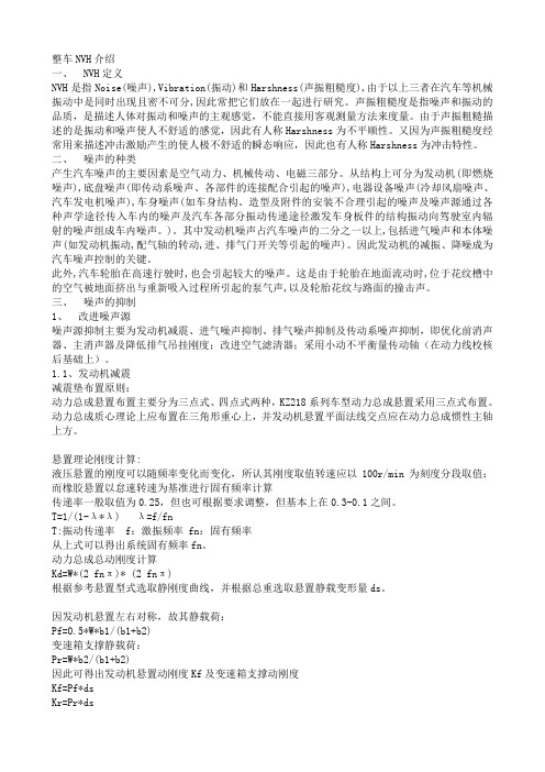
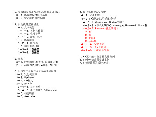
EnginemountsNVH专业资料1
汽车NVH介绍普及

NVH的分类
按照影响程度,NVH问题可以分为两类:一类是影响汽车驾 驶员和乘客舒适性的问题,如车内噪声过大、振动明显等; 另一类是影响汽车性能的问题,如发动机振动、传动系统异 响等。
按照产生机理,NVH问题可以分为空气动力性NVH问题、机 械性NVH问题和电磁性NVH问题三类。
车身振动是指汽车在行驶过程中, 由于路面不平、发动机运转等因
素引起的车身振动。
车身振动不仅影响乘坐舒适性, 还会影响汽车零部件的寿命。
降低车身振动的方法包括优化悬 挂系统设计、采用减震器等,以
提高汽车的稳定性。
声振耦合
声振耦合是指汽车在行驶过程中,由 于各种噪声和振动源的相互作用,使 得噪声和振动在车内传播和叠加的现 象。
03
在汽车研发和生产过程中,解决NVH问题需要投入大量 的人力和物力,因此,对于汽车企业和零部件供应商来 说,NVH性能的提升也是提高产品质量和降低成本的重 要途径之一。
02 NVH的主要影响因素
发动机噪音
发动机是汽车的主要噪声源之一,其产生的噪音包括燃烧噪音、机械运动噪音等。 发动机的转速、负荷和燃烧方式等因素都会影响发动机噪音的大小。
降低发动机噪音的方法包括优化设计、采用降噪技术等,以提高汽车的舒适性。
风噪和路噪
风噪是指汽车在高速行驶时, 空气与车身相互作用产生的噪 音。
路噪是指汽车轮胎与路面摩擦 产生的噪音,以及车身振动产 生的噪音。
降低风噪和路噪的方法包括优 化车身外形设计、采用隔音材 料等,以提高汽车的静谧性。
车身振动
汽车nvh介绍普及
目录
• 什么是NVH • NVH的主要影响因素 • NVH的改善措施 • NVH的未来发展趋势 • 案例分析
整车NVH介绍

整车NVH介绍一、 NVH定义NVH是指Noise(噪声),Vibration(振动)和Harshness(声振粗糙度),由于以上三者在汽车等机械振动中是同时出现且密不可分,因此常把它们放在一起进行研究。
声振粗糙度是指噪声和振动的品质,是描述人体对振动和噪声的主观感觉,不能直接用客观测量方法来度量。
由于声振粗糙描述的是振动和噪声使人不舒适的感觉,因此有人称Harshness为不平顺性。
又因为声振粗糙度经常用来描述冲击激励产生的使人极不舒适的瞬态响应,因此也有人称Harshness为冲击特性。
二、噪声的种类产生汽车噪声的主要因素是空气动力、机械传动、电磁三部分。
从结构上可分为发动机(即燃烧噪声),底盘噪声(即传动系噪声、各部件的连接配合引起的噪声),电器设备噪声(冷却风扇噪声、汽车发电机噪声),车身噪声(如车身结构、造型及附件的安装不合理引起的噪声及噪声源通过各种声学途径传入车内的噪声及汽车各部分振动传递途径激发车身板件的结构振动向驾驶室内辐射的噪声组成车内噪声。
)。
其中发动机噪声占汽车噪声的二分之一以上,包括进气噪声和本体噪声(如发动机振动,配气轴的转动,进、排气门开关等引起的噪声)。
因此发动机的减振、降噪成为汽车噪声控制的关键。
此外,汽车轮胎在高速行驶时,也会引起较大的噪声。
这是由于轮胎在地面流动时,位于花纹槽中的空气被地面挤出与重新吸入过程所引起的泵气声,以及轮胎花纹与路面的撞击声。
三、噪声的抑制1、改进噪声源噪声源抑制主要为发动机减震、进气噪声抑制、排气噪声抑制及传动系噪声抑制,即优化前消声器、主消声器及降低排气吊挂刚度;改进空气滤清器;采用小动不平衡量传动轴(在动力线校核后基础上)。
1.1、发动机减震减震垫布置原则:动力总成悬置布置主要分为三点式、四点式两种,KZ218系列车型动力总成悬置采用三点式布置。
动力总成质心理论上应布置在三角形重心上,并发动机悬置平面法线交点应在动力总成惯性主轴上方。
NVH基本知识介绍

NVH 含义
N= Noise V=Vibration H=Harshness 噪声是人耳感受到的由于空气的压力变化
产生的扰动. 振动是在某个频率或一系列频率下围绕参
考点产生的振荡运动 Harshness(粗糙的振动和噪声)
名词介绍
声压:由于声扰动产生的压强
声压级:人耳可听的声压范围相差一百万倍,不方便表示能量的大小,所 以在声学中采用对数坐标来描述声音的大小,这就是级的概率.声压级 的基准声压是2*10e-5, SPL=20lg(P/P0) ,P0=2*10e-5
建立stick mode预测车身的模态,扭转和弯曲刚度 接头分析
在开发的早期阶段分析及优化截面和接头的性能,减少设计缺 陷.
CAD 设计阶段: CAE部分
BIW 模态和刚度分析 开启件的刚度和模态分析 Trimmed body模态分析 Point mobility分析和振动传递函数分析 声学模态分析 声学传递函数和钣金贡献量分析 发动机悬置支架分析 排气吊挂位置分析 发动机悬置位置和刚度优化 进排气系统声学分析 底盘件模态分析 高频噪声分析(统计能量法) 风噪声分析(CFD)
开发主要又分为两个阶段,首先需要制订详细的开发计划:如下 表.
开发阶段的主要试验内容:
1. 零部件试验:
2. 白车身的模态试验:对CAE的分析结果进行验证.
3. 声学灵敏度测试: 检查整车关键点的声学灵敏度有没有 达到设计要求,并与CAE分析结果进行验证.
4. 结构灵敏度:检查整车关键点的结构灵敏度有没有达到 设计要求,并与CAE分析结果进行验证.
发动机、传动系 等运动机构
孔 缝 泄 漏 噪 声
进气、排气、冷却风扇等 空气动力性噪声
EngineMT design

3
引擎悬置设计
Absorption
The term absorption applies to the tuning of the mounts so that the vibrations within the system are 180° out of phase with critical road input or structural response (typically 20 Hz and below). The following criteria is used in the tuning for the six degrees of freedom:
5
引擎悬置设计
引擎悬置相互作用示意图
6
引擎悬置设计
引擎悬置安排种类
7
引擎悬置设计
纵向引擎 SUV, or 卡车悬置
Sub-frame based 3 mount system
8
引擎悬置设计
3 mounts
4 mounts
9
引擎悬置设计
前-后方向
10
引擎悬置设计
4-point East – West (Pendulum) Mount System
functions:
设计功能
• Support and locate the engine/transmission assembly
• Control/restrict movement of the engine/transmission assembly
• Isolate the engine/transmission assembly for NVH
Bounce
分配到需要的位置
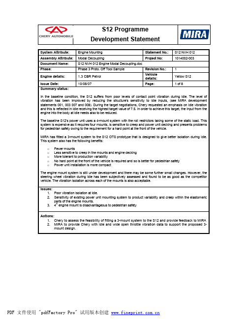
NVH 012 Engine Modal Decoupling

x 95 330 57 48
Baseline (N/mm)*1.4 x y z 133 462 259 462 118 210 80 392 91 67 203 140
Table 1. Mount position and stiffness data used in the kinetic energy simulation – S12 baseline condition
A-mount in engine axis system B-mount in engine axis system C-mount in engine axis system D-mount in engine axis system
x 514 -340 -52
mm y 10 22 -220
z 215 215 -197
KE Distributions - Engine Axis System RHR
x y z Rx Ry Rz
0
5
10 15 Frequency (Hz)
20
25
0
5
10 15 Frequency (Hz)
20
25
Figure 1. Kinetic energy distribution for the rigid body modes of the power unit - baseline S12 using data supplied by Chery. Comments 1. The frequencies are quite high and imply that it may be possible to use softer mounts to improve vibration isolation 2. There is some coupling between Rx (torque parallel to the crank) and translations in the vertical and fore-aft directions which imply that driveability may be compromised with respect to modal coupling.
汽车NVH介绍

NVH与频率的关系
长安汽车(集团)有限责任公司
路面及动力系统 的振动
Road & P/T Vibration
路面及动力系统的噪声Road & P/T Sound
风激励噪声Wind Noise
动力系统的声品质
P/T Sound Quality
0 Hz
100 Hz
250 Hz
800 Hz
5000 Hz
• Control: – vehicle shape – sealing
> 90 km/h
28
1. NVH现象与基本问题 2. 噪声与振动源
3.NVH传递通道
4. NVH的响应与评估 5. NVH试验 6. NVH的CAE分析 7. NVH开发及目标体系 8. 汽车声品质
长安汽车(集团)有限责任公司 29
2
Engine speed (rpm)
6000
• 1 cylinder engine: firing order: ½ order • 2 cylinder engine: firing order: 1st order • 4 cylinder engine: firing order: 2nd order • 6 cylinder engine: firing order: 3rd order
Powertrain
Mount
Intake
Powerplant
动力总成 Powerplant
Exhaust
Driveline
Engine
司 13
发动机噪声源
燃烧噪声
活塞载荷 气缸盖载荷 曲轴轴承载荷
机械振动与噪声
曲轴系统 突轮轴系统 链,齿轮,皮带 非燃烧引起的冲击 附件
发动机悬置设计4

〇
Nissan Note
1.2supchgDI CVT
O-balance Pendulum
〇
China A test-car
1.0TDI 6AT +N-idle
Nothing Pendulum
〇
Engineering judgement for NVH
1)Outer-balance and Pendulum is OK ⇒we need check our design
2nd gear toothing
Motor noise
100
600
rotation unbalance
2K
12K
Electro-magnetic noise
power-plant bending1 power-plant bending2
Igen values AC compressor
distribution
Φ85mm
Type B
4点Pendulum和Upper T-rod的案例(1)
数值Upper T-rod的案例
2-3. Pendulum悬置的案例 1) 右 2) 左
3) T-rod 4) 三缸机
3)Engine-mount for new 3cylinder
If we put hydraulic resonance at 15Hz, New peak comes up at 20-24Hz
Diff order noise
Typical EV acceleration Noise 3D MAP
400Hzat3000rpm
3) 2)
800Hzat1000rpm
工程机械NVH基础 ppt课件

噪声、振动与舒适性三者密切相关。既要减小振动,降低噪声,又要提高 乘坐舒适性。
与节能、再制造、混合动力和不断更新的排放标准相比,减振降噪似乎算 不上行业热衷的词汇。然而,减振降噪研究的技术含量和重要程度并不亚于其 它任何一项研究。
第三类:已知系统和响应,求激励 。称为载荷识别(振 动环境预测),又称为第二类逆问题。
ppt课件
17
振动基础——振动系统描述
求解振动问题的主要目的是要确定在任何给定时刻系统 的位移、速度、加速度等。
单自由度系统是振动研究中最简单的一类系统,仅用一 个坐标就可以确定该类系统的运动状态。
ppt课件
18
ppt课件
6
振动基础——振动灾害举例1
部队经过桥梁时不能齐步走,为了避免桥因共振而坍塌
ppt课件
7
振动基础——振动灾害举例2
1940 年11月7日美国 Tocama 悬索桥风毁事故。
ppt课件
8
振动基础——振动的利用与控制
琴弦振动; 通信、广播等; 振动沉桩、振动拔桩
以及振动捣固等; 振动检测; 振动压路机; 振动给料机; 振动成型机 振动筛等。
ppt课件
22
振动基础——无阻尼单自由度自由振动
振动方向相同的简谐振动合成:
两个同频率简谐振动的合成 两个不同频率简谐振动的合成 两个频率十分接近的简谐振动合成
ppt课件
23
振动基础——无阻尼单自由度自由振动
振动方向相互垂直的简谐振动合成:
同频率两个简谐振动在同一平面内沿相互垂方向直合成后的运动轨 迹一般为椭圆,频率不同时合成后的运动轨迹较为复杂。当频率之间存 在一定比例关系时,合成后的运动轨迹呈现出稳定的有规律的结果。借 助于双线示波器我们可以观察到这些有趣的图形,这些图形被称为李萨 育图。
- 1、下载文档前请自行甄别文档内容的完整性,平台不提供额外的编辑、内容补充、找答案等附加服务。
- 2、"仅部分预览"的文档,不可在线预览部分如存在完整性等问题,可反馈申请退款(可完整预览的文档不适用该条件!)。
- 3、如文档侵犯您的权益,请联系客服反馈,我们会尽快为您处理(人工客服工作时间:9:00-18:30)。
starts, hill starts
• Isolation
– Ride Comfort 2- 20Hz – Noise and Vibration 20Hz+
• Engine Location
– Compression set – Power unit / engine bay positioning – Torque control -tip in/ tip out , gear shift
Lotus experience of engine mounts
• Design of mounting concept for engine
– NTA 3 point , NTA 4 point, 3 point , 4 point mounting – Location of engine mounts relative to engine torque axis (CAE)
• First strategy is far more common approach.
• If the bodystructure was infinitely stiff then no structural
noise would be generated. (bedplate).
• Body sensitivity is measured by INPUT POINT MOBILITY
Powertrain bending mode 138Hz
Practical engine mount design
• There is no single right location for an engine mount system. • Idealised mounting positions may not be achievable due to
• Engine solid body modes are shifted to either
coincide or avoid vehicle system modes.
• Decouple / avoid modes - example
– Engine roll
8Hz
– Engine Bounce – Engine pitch
• Engine side mounting design
– Refinement, durability (FEA)
• Engine mount detailed design • Body structural design of engine mounts (FEA) • NVH development of engine mount rates , brackets • Ride / shake development of engine mounts • Transient engine load reaction (shunt reaction) • Modal testing of powertrain modes in vehicle
engine torque.
• In some mounting concepts static load and torque reaction are
done by separate mounts in other concepts mounts provide reaction to both kinds of load.
Bodyside bracket front reinforced
Bodyside bracket rear reinforced
Engine block pick up - improved casting
Improved noise at 4800rpm
Engine relation to vehicle modes
Engine Bounce mode - 10.8Hz
Engine fore aft mode 11.8Hz
Engine roll mode 14.3Hz
Engine pitch mode 14.8Hz
Engine yaw mode 16.8Hz
Engine Flexural modes
Engine mounting concepts
• The generally used engine mounting concepts use either 3 or 4
main mounts.
• At least 2 mounts must bear the static weight of the engine. The
geometry and package.
• Locating mounts with minimal offsets from structural members
or the main block leads to good refinement - this can be far better than an idealised position that requires long brackets or high offsets.
Engine mount example
Engine mount response measured
• Strong vibration found
on engine RH engine mount.
Engine side - overall level Body side - overall level Engine side 2nd order Body side 2nd order
• Overall good mount
attenuation Engine side to Body sideElastomer rates are therefore OK.
Structural changes to engine mounts
Reinforced engine side mount
Engine rigid body behaviour
• Modes are influenced by powertrain
– Mass , C of G, directions of inertia axis
• Modes are influenced by mounting system
– Number and location of mounts, mount orientation, mount stiffness
• Generally more
problematic on RWD installations
– Bending mode usually sub
200Hz
– System mass higher
• Ideal mount position is
on nodal points of bending mode to prevent energy transfer into body structure
Engine mount functions
• Static Load acceptance
– Hold the mass of the engine
• Dynamic load acceptance
– Vehicle- braking, cornering, kerb strike,
bumps, crash
and damping
• Six Natural modes can be expected
Fore aft (x) Lateral (y)
Bounce (z)
Roll (Rx) Pitch (Ry)
Yaw (Rz)
Some of these modes are often difficult to identify especially if 2 modes are virtually co-incident - e.g. lateral (Y) in following example
• For a force acting on a mount generating vibration
– Sound power (Structural noise) Mechanical power transfer – Mechanical Power transfer Force x velocity – Body mount mobility m/s/N provides correlation to noise path seor different engine derivatives may
determine a compromise location is selected.
• Other vehicle requirements such as crash performance can
influence location and stiffness of engine mounts.
• Manufacturing requirements for engine installation can also
influence engine mount location ( e.g. assembly access)
3 point mount - milking stool
All 3 mounts carry the mass of the engine and react engine torque
4 point platform
All 4 mounts carry the mass of the engine and react engine torque Distribution of forces varies with geometry tolerances
