隧道施工设计外文翻译--新意法的设计与施工
地铁隧道毕业设计外文翻译
外 文 翻 译
年 级: 2005 级 学 号:20057375 姓 名: 黄 磊 专 业:铁道工程 指导老师: 钟新樵
2009 年 6 月
西南交通大学本科毕业设计(论文)外文翻译
第1页
【原文】
A study on underground tunnel ventilation for piston effects influenced by draught relief shaft in subway system
西南交通大学本科毕业设计(论文)外文翻译
第3页
Cm
For air inflow,
AvVv Qb AV Qc
(1)
Cm K i
For air outflow,
ቤተ መጻሕፍቲ ባይዱAv A
Cp Cps
(2)
Cm K o where A Av Cm tunnel area (m2) relief shaft area (m2)
CΔHi Ki, Ko Qb, Qc
entrance loss at the bottom of relief shaft empirical constants for inflow and outflow air flow volume rate through relief shaft and upstream(or downstream) (m3/s)
Chi-Ji Lin, Yew Khoy Chuah, Chia-Wei Liu
Abstract
This is a study on underground tunnel ventilation for piston effects influenced by draught relief shaft. Field measurements of transient air movement in the draught relief shaft for a typical Taipei underground subway station were taken under winter and summer conditions. It has been found that the air in the draught relief shaft has a maximum of 2 m/s, and on average lies between 0.7 and 1.1 m/s. This study defines an index ηPE, for evaluating the efficiency of tunnel ventilation by piston effects. This index can be used to analyze the piston effects due to different shaft length and sectional area. The measurement results show that the train piston effects are effective only for certain shaft length and operating conditions. This study also used the authoritative SES computer program to simulate the piston effects. The simulation results for inflow and outflow velocity profile are almost consistent with the measurement. The shaft sectional area was also investigated and has been found that a larger sectional area resulted in larger volume flow rate, but the percentage increase is less than the percentage increase in the sectional area. This will result in smaller air velocity in shaft and less effective air exchange between the tunnel and the outside ambient. It also has been found that length of the draught relief shaft is more so an important design parameter for efficient air exchange by piston effects for underground subway systems. It is suggested here that the design of the draught relief shaft has to consider requirements including ηPE, pressure loss and noise.
隧道盾构-毕设论文外文翻译(翻译-原文)
毕业设计(论文)外文文献翻译院系:土木工程与建筑系年级专业:土木工程姓名:学号:附件:盾构SHIELDS指导老师评语:指导教师签名:年月日S HIEL D S【Abstr act】A tunnel shield is a structural system, used during the face excavation process. The paper mainly discusses the form and the structure of the shield. Propulsion for the shield is provided by a series of hydraulic jacks installed in the tail of the shield and the shield is widespread used in the underground environment where can not be in long time stable. The main enemy of the shield is ground pressure. Non-uniform ground pressure caused by the steering may act on the skin tends to force the shield off line and grade. And working decks inside the shield enable the miners to excavate the face, drill and load holes.【Keywor ds】shield hydraulic jacks ground pressure steering working decksA tunnel shield is a structural system, normally constructed of steel, used during the face excavation process. The shield has an outside configuration which matches the tunnel. The shield provides protection for the men and equipment and also furnished initial ground support until structural supports can be installed within the tail section of the shield. The shield also provides a reaction base for the breast-board system used to control face movement. The shield may have either an open or closed bottom. In a closed-bottom shield, the shield structure and skin provide 360-degree ground contact and the weight of the shield rests upon the invert section of the shield skin. The open shield has no bottom section and requires some additional provision is a pair of side drifts driven in advance of shield excavation. Rails or skid tracks are installed within these side drifts to provide bearing support for the shield.Shield length generally varies from1/2 to 3/4 of the tunnel diameter. The front of the shield is generally hooded to so that the top of the shield protrudes forward further than the invert portion which provides additional protection for the men working at the face and also ease pressure on the breast-boards. The steel skin of the shield may varyfrom 1.3 to 10 cm in thickness, depending on the expected ground pressures. The type of steel used in the shield is the subject of many arguments within the tunneling fraternity. Some prefer mild steel in the A36 category because of its ductility and case of welding in the underground environment where precision work is difficult. Others prefer a high-strength steel such as T-1 because of its higher strength/w eight ratio. Shield weight may range from 5 to 500 tons. Most of the heaviest shields are found in the former Sovier Union because of their preference for cast-iron in both structural and skin elements.Propulsion for the shield is provided by a series of hydraulic jacks installed in the tail of the shield that thrust against the last steel set that has been installed. The total required thrust will vary with skin area and ground pressure. Several shields have been constructed with total thrust capabilities in excess of 10000 tons. Hydraulic systems are usually self-contained, air-motor powered, and mounted on the shield. Working pressures in the hydraulic system may range from 20-70 Mpa. To resist the thrust of the shield jacks, a horizontal structure member (collar brace) must be installed opposite each jack location and between the flanges of the steel set. In addition, some structural provision must be made for transferring this thrust load into the tunnel walls. Without this provision the thrust will extend through the collar braces to the tunnel portal.An Englishman, Marc Brunel, is credited with inventing the shield. Brunel supposedly got his idea by studying the action of the Teredo navalis, a highly destructive woodworm, when he was working at the Chatham dock yard. In 1818 Brunel obtained an English patent for his rectangular shield which was subsequently uses to construct the first tunnel under the River Thames in London. In 1869 the first circular shield was devised by Barlow and Great Head in London and is referred to as the Great Head-type shield. Later that same year, Beach in New York City produced similar shield. The first use of the circular shield came during 1869 when Barlow and Great Head employed their device in the construction of the 2.1 in diameter Tower Subway under the River Thames. Despite the name of the tunnel, it was used only for pedestrian traffic. Beach also put his circular shield to work in 1869 to construct a demonstration project for a proposed NewYork City subway system. The project consisted of a 2.4 m diameter tunnel, 90 m long, used to experiment with a subway car propelled by air pressure.Here are some tunnels which were built by shield principle.Soft-ground tunneling Some tunnels are driven wholly or mostly through soft material. In very soft ground, little or no blasting is necessary because the material is easily excavated.At first, forepoling was the only method for building tunnels through very soft ground. Forepoles are heavy planks about 1.5 m long and sharpened to a point. They were inserted over the top horizontal bar of the bracing at the face of the tunnel. The forepoles were driven into the ground of the face with an outward inclination. After all the roof poles were driven for about half of their length, a timber was laid across their exposed ends to counter any strain on the outer ends. The forepoles thus provided an extension of the tunnel support, and the face was extended under them. When the ends of the forepoles were reached, new timbering support was added, and the forepoles were driven into the ground for the next advance of the tunneling.The use of compressed air simplified working in soft ground. An airlock was built, though which men and equipment passed, and sufficient air pressure was maintained at the tunnel face to hold the ground firm during excavation until timbering or other support was erected.Another development was the use of hydraulically powered shields behind which cast-iron or steel plates were placed on the circumference of the tunnels. These plates provided sufficient support for the tunnel while the work proceeded, as well as full working space for men in the tunnel.Under water tunneling The most difficult tunneling is that undertaken at considerable depths below a river or other body of water. In such cases, water seeps through porous material or crevices, subjecting the work in progress to the pressure of the water above the tunneling path. When the tunnel is driven through stiff clay, the flow of water may be small enough to be removed by pumping. In more porous ground,compressed air must be used to exclude water. The amount of air pressure that is needed increases as the depth of the tunnel increases below the surface.A circular shield has proved to be most efficient in resisting the pressure of soft ground, so most shield-driven tunnels are circular. The shield once consisted of steel plates and angle supports, with a heavily braced diaphragm across its face. The diaphragm had a number of openings with doors so that workers could excavate material in front of the shield. In a further development, the shield was shoved forward into the silty material of a riverbed, thereby squeezing displaced material through the doors and into the tunnel, from which the muck was removed. The cylindrical shell of the shield may extend several feet in front of the diaphragm to provide a cutting edge. A rear section, called the tail, extends for several feet behind the body of the shield to protect workers. In large shields, an erector arm is used in the rear side of the shield to place the metal support segments along the circumference of the tunnel.The pressure against the forward motion of a shield may exceed 48.8 Mpa. Hydraulic jacks are used to overcome this pressure and advance the shield, producing a pressure of about 245 Mpa on the outside surface of the shield.Shields can be steered by varying the thrust of the jacks from left side to right side or from top to bottom, thus varying the tunnel direction left or right or up or down. The jacks shove against the tunnel lining for each forward shove. The cycle of operation is forward shove, line, muck, and then another forward shove. The shield used about 1955 on the third tube of the Lincoln Tunnel in New York City was 5.5 m long and 9.6 m in diameter. It was moved about 81.2 cm per shove, permitting the fabrication of a 81.2 cm support ring behind it.Cast-iron segments commonly are used in working behind such a shield. They are erected and bolted together in a short time to provide strength and water tightness. In the third tube of the Lincoln Tunnel each segment is 2 m long, 81.2 cm wide, and 35.5 cm thick, and weighs about 1.5 tons. These sections form a ring of 14 segments that are linked together by bolts. The bolts were tightened by hand and then by machine.Immediately after they were in place, the sections were sealed at the joints to ensure permanent water tightness.Shields are most commonly used in ground condition where adequate stand-up time does not exist. The advantage of the shield in this type of ground, in addition to the protection afforded men and equipment , is the time available to install steel ribs, liner plates, or precast concrete segments under the tail segment of the shield before ground pressure and movement become adverse factors.One of the principle problems associated with shield use is steering. Non-uniform ground pressure acting on the skin tends to force the shield off line and grade. This problem is particularly acute with closed bottom shield that do not ride on rails or skid tracks. Steering is accomplished by varying the hydraulic pressure in individual thrust jacks. If the shied is trying to dive, additional pressure on the invert jacks will resist this tendency. It is not unusual to find shield wandering several feet from the required. Although lasers are frequently used to provide continuous line and grade data to operator, once the shield wanders off its course, its sheer bulk resists efforts to bring it back. Heterogeneous ground conditions, such as clay with random boulders, also presents steering problems.One theoretical disadvantage of the shield is the annular space left between the support system and the ground surface. When the support system is installed within the tail section of the shield, the individual support members are separated from the ground surface by the thickness of the tail skin. When steel ribs are used, the annular space is filled with timber blocking as the forward motion of the shield exposes the individual ribs.A continuous support system presents a different problem. In this case, a filler material, such as pea gravel or grout, is pumped behind the support system to fill the void between it and the ground surface.The main enemy of the shield is ground pressure. As ground pressure begins to build, two things happen, more thrust is required for shield propulsion and stress increases in the structural members of the shield. Shields are designed and function undera preselected ground pressure. Designers will select this pressure as a percentage of the maximum ground pressure contemplated by the permanent tunnel design. In some cases, unfortunately, the shield just gets built without specific consideration of the ground pressures it might encounter. When ground pressure exceeds the design limit, the shield gets “stuck”.The friction component of the ground pressure on the skin becomes greater than the thrust capability of the jacks. Several methods, including pumping bentonite slurry into the skin, ground interface, pushing heavy equipment, and bumping with dynamite, have been applied to stuck shields with occasional success.Because ground pressure tends to increase with time, the cardinal rule of operation is “keeping moving”.This accounts for the fracture activity when a shield has suffered a temporary mechanical failure. As ground pressure continues to build on the nonmoving shield , the load finally exceeds its structural limit and bucking begins. An example of shield destruction occurred in California in 1968 when two shields being used to drive the Carly V.Porter Tunnel were caught by excessive ground pressure and deformed beyond repair. One of the Porter Tunnel shields was brought to a halt in reasonably good ground by water bearing ground fault that required full breast-boards. While the contractor was trying to bring the face under control, skin pressure began to increase. While the face condition finally stabilized, the contractor prepared to resume operations and discovered the shield was stuck. No combination of methods was able to move it, and the increasing ground pressure destroyed the shield.To offset the ground pressure effect, a standard provision in design is a cutting edge radius several inches greater than the main body radius. This allows a certain degree o f ground movement before pressure can come to bear on the shield skin. Another approach, considered in theory but not yet put into practice, is the “w atermelon seed”design. The theory calls for a continuous taper in the shield configuration; maximum radius at the cutting edge and the minimum radius at the trailing edge of the tail. With this configuration, any amount of forward movement would create a drop in skin pressure.Working decks, spaced 2.4 to 3.0 m vertically, are provided inside the shield. These working decks enable the miners to excavate the face, drill and load holes, if necessary, and adjust the breast-board system. The hydraulic jacks for the breast-board are mounted on the underside of the work decks. Blast doors are sometimes installed as an integral part of the work decks if a substantial amount of blasting is expected.Some form of mechanical equipment is provided on the rear end of the working decks to assist the miners in handing and placing the element of the support system. In large tunnels, these individual support elements can weigh several tons and mechanical assistance becomes essential. Sufficient vertical clearance must be provided between the invert and the first working deck to permit access to the face by the loading equipment.盾构【摘要】隧道盾构是一结构系统,通常用于洞室开挖。
新意法
一、基本原理
隧道掘进时对隧道周边及前方一定范围的围岩 产生扰动,改变了围岩原始应力状态。在开挖面周 边区域内,围岩由三轴应力逐渐转变为平面应力状 态,开挖面及前方一定范围内围岩应力重分布。开 挖后围岩变形也在扰动区域内提前发生。
当开挖面前方围岩的应力状态处于弹性范围内时, 在开挖轮廓线 附近产生弹性变形 , 称为“ 拱部效 应”,这时开挖面处于稳定状态;
拱部效应
拱部效应
拱部效应
拱部效应
自然拱部效应
自然拱部效应
转移拱部效应
转移拱部效应
如果开挖后围岩处于弹~塑性状况,开挖轮廓四 拱部效应
拱部效应
周及开挖面将朝隧道内产生塑性变形,“拱部效应” 将从开挖轮廓周围往外移到地层中,但此“转移” 只能通过足够的支护措施来实现和控制; 自然拱部效应
转移拱部效应
无拱部效应
施工
注:(*)变形现象是指,开挖面挤压及在岩层体内部一定的变化距离 内的收敛。
二、实施要点
该工法分为两个实施阶段:在设计阶段完成地质 勘察、诊断及处理措施设计;施工阶段则边实施作 业边监控量测,然后优化调整,使开挖面和洞身结 构体系形成平衡,保持稳定。
勘察
设计阶段 诊断 处治 设计阶段
实施
监测 反馈
意大利博洛尼亚一佛罗伦萨高速铁路隧道工程
意大利博洛尼亚一佛罗伦萨高速铁路全长约92km,其 中隧道总长84.5 km。隧道穿越复杂多变的、极差的地 层,断面面积约140 m2 。该项目采用“新意法” 编制 设计规范,并以此为基础进行工程招标和施工设计。 该工程地质条件虽很差,但是,由于按“新意法” 进 行设计和施工,把风险降到了最低,因此仍以“交钥 匙”合同方式发包。该工程于1998年开工,全断面开 挖,机械化程度很高。工程进展顺利,每个工作面平 均月成洞50m。“新意法”在该工程中的应用取得了 巨大成功。
隧道设计与施工
14
世界著名隧道
1
我国自主建成的一座铁路隧道?
2
“世界第一高隧道”
3
世界上最长的一条隧道
4
世界海底长度最长的隧道
15
京张铁路八达岭隧道
它是中国杰出的
工程师詹天佑亲 自规划督造,依 靠中国人自己的 力量建成的第一 座铁路隧道。这 座单线越岭隧道 全长1091米,工 期仅用了18个月。
16
青藏铁路风火山隧道
21
22
2
全长:18.02km
3
“四步走战略”
1 2 3 4
Planning 规划
Survey 勘测 Design 设计
Construction 施工
4
Design - the Soul of Construction
Design
Principles
设计原则
emphasis on technology and economic benefits 重视技术与经济效益的结合。 focus on aesthetics, application and coordination 注重美观、适用和协调、 human-based 以人为本
“短进尺、弱不爆破、强支护、紧衬砌”
Main
processes
excavation 、tapping 、shoring、lining
开挖、出渣、支护、衬砌
8
9
Methods of construction
Mine tunneling method 矿山法 New Austrian Tunneling Method 新奥法 Tunnel-Boring Machine method 掘进机法 Shield method盾构法 Immersed tube method 沉管法 Pipe jacking method 顶进法 Cut and Cover Method 明挖法 Cover and cut-bottom up 盖挖法
地铁隧道施工外文文献翻译
地铁隧道施工外文文献翻译(文档含中英文对照即英文原文和中文翻译)原文:Urban Underground Railroad arch tunnel Construction Technology GroupAbstract Project in Guangzhou Metro Line, right-arch construction method of tunnels to explore. Subway Construction in Guangzhou for the first time put forward a double-arch tunnel to single-hole tunnel construction technology, and a single type of wall and split in the wall structure, comparison and selection of Technology solutions were obtained to meet the structural safety, construction safety and Economic benefits of better Technology solutions for the future design and construction of similar projects to provide reference and reference.Keywords: double-arch tunnel group; a single type of wall; construction Technology; split in the wall.As the circuit design requirements subway tunnel, the tunnel structure produces a variety of forms, ranging from cross-section from double-arch and the three-arch tunnel composed of double-arch tunnel section is commonly used in the connection lines andcrossing lines. In this paper, engineering examples, according to tunnel in which geological conditions, duration requirements, raised through the comparison and selection can achieve rapid construction and the purpose of construction cost savings of the best construction programs.1 Project OverviewGuangzhou Metro Line Road station turn-back line of sports for sports Road station after the return line, structure complex, DK3 016.047 ~ 037.157 varying cross-section set the double-arch structure, three-arch structure of tunnels. Ranging from cross-arch tunnel excavation span 20.1m, excavation height of 10.076m, cross-vector ratio of 1:0.5, after lining a hole span 5.2m, large holes, after lining span 11.4m, the wall thickness of 1.6 m. Three double-arch tunnel excavation span 19.9m, excavation height of 7.885m, cross-vector ratio of 1:0.1. -Arch tunnel section of rock from top to bottom are: artificial fill soil, red - alluvial sand, alluvial - alluvial soil, river and lake facies soil, plastic-like residual soil, hard plastic - a hard-like residual soil, all weathered rock, strong weathering rock, the weathered layer and the breeze layer. Tunnel through the rock strata are more homogeneous, the intensity high, carrying ability, good stability. Thickness of the tunnel vault covering 15.5 ~ 18m, of which grade ⅣWai rock vault thickness 5.6 ~ 7.6m. Double-arch tunnel segment groundwater table is 2.28 ~ 4.1m, mainly Quaternary pore water and fissure water.Section 2 dual-arch construction scheme comparisonAs the double-arch tunnel segment structure more complex, the tunnel cross-section changes in large, complicated construction process, construction was very difficult, the construction cycle is long, so I chose a good quality and efficient completion of the construction program segment arch tunnel construction is particularly important. Selection of a construction program, the main consideration the following aspects: (1) construction safety and structural safety; (2) construction difficulties; (3) the construction cycle; (4) cost-effectiveness. Based on these four principles, through the construction of research and demonstration program to select the following two programs to compare the selection of the construction.2.1 a single type of wall construction planThe program's main construction steps and measures are as follows:(1) The right line of double-arch tunnel hole within the return line side of temporary construction access, dual-arch and the three-arch in the wall construction, is completed in a timely support for the wall, the construction to prevent bias.(2) construction of the wall lining is completed, according to "first small then big, closed into a ring" principle, the right line with the step method of construction, with CRD engineering method returned a four-lane span tunnel construction.(3) When the return line side of the construction to the three-arch tunnel in the wall, then in accordance with the right line of the wall construction method and the three-arch-arch in the wall construction, during which the right line to stop excavation until the completion of construction of the wall.(4) The return line side of the wall construction is completed, the right line to continue to move forward the construction.The construction method for the domestic double-arch tunnel of conventional construction method, Guangzhou Metro, Nanjing and Beijing Metro subway both applications, and can secure successful completion of the construction of tunnels. However, examples of past engineering and construction Technology research can be found, the program has weaknesses and shortcomings.(1) The program used in this project, in a short span of 21.11m of double-arch tunnel, the tunnel's opening between the supporting and secondary lining will be converted four times, the conversion too frequently.(2) wall and side holes covered by waterproof layer of tunnel lining construction, steel engineering, formwork, concrete pouring required multiple conversions, the construction period up to 2 months.(3) The lining is completed, the wall of anti-bias materials, equipment, support and input, resulting in higher construction costs, Economic efficiency will drop.2.2 The split in the wall construction planThe program's main construction steps and measures are as follows:(1) ranging from cross-double-arch tunnel into two single-hole, change the formula for the separation wall, the first line of one-way right-forward construction of the tunnel.(2) three arch tunnel in the wall to make the first non-Shi lining, according to single-line working condition through.(3) the right line of large-section double-arch tunnel wall construction method adopted in accordance with CRD.(4) The return line is in accordance with the right line of the opposite side of the construction sequence of construction.Adoption of this program is in fact a one-way in accordance with the construction of two methods, compared with the previous one, after the program has the following advantages:(1) reduction of the construction process to speed up the convergence process conversion.(2) reduce the construction difficulty, shortening the construction cycle.(3) reduce the construction costs and improve Economic efficiency.(4) change a single type of wall to separate the wall, completely solved the structure of double-arch tunnel waterproofing defects.(5) The three-arch tunnel in the latter pArt of the construction hole, equivalent to large-span rock tunnels reserved for the core is conducive to both sides of the double-arch tunnel construction safety (Table 1).Section 3 three-arch construction planRight-line direct access to three double-arch tunnel, the Support parameters to the original designs for grating erection of the whole ring, according to design the whole ring of shotcrete, and enhance the bolt at the wall vault settings (return right side Tong Line Construction method), wall construction in the tunnel when you need to get rid of Office, located at a vertical grill joints strengthened beam.Strict control of excavation footage of each cycle, grid spacing of 0.6m / Pin. Weak in the wall excavation using millisecond blasting program (conditional maximize the use of static blasting programs), minimize the wall rock and the lining of the tunnel has beendisturbed, to ensure construction safety. The completion of excavation in the wall immediately after the secondary lining. After the completion of construction of the wall in wall voids of the backfilling, plus jack supports. The side of the construction is completed, carry out the other side of the wall construction. When both sides of the wall construction is complete, in a timely manner on both sides of a single-hole tunnel secondary lining, and then proceed to three-arch tunnel excavation and lining of the middle of rock. Construction, special attention should be three arch tunnel in the wall at the settlement and convergence deformation, such as the unusual phenomenon, an immediate reinforcement.4 construction of the force structure of Behavior AnalysisAcross the range of the double-arched wall canceled, changed to separate the wall, in the domestic urban underground railway engineering has not yet been a similar engineering design and construction experience, there is no such tunnel structure design, and therefore the structure is safe, as well as the course of construction conversion process of construction is safe, the program will be the focus of the study.Application of ANSYS finite element software for common procedures ranging from cross-arch tunnel numerical simulation, using stratigraphic - structural model of the structure of the tunnel by the force and deformation analysis (Figure 1, Figure 2, Figure 3). The scope of the horizontal direction taken by force along the direction of the tunnel cross-section to cross-hole 3 times the limit, taking the top of the vertical direction to the surface, the bottom-hole span to 3 times the limit, unit model uses the DP formation of elastic-plastic material entity, the tunnel Lining with elastic beam element simulation, beam elements and solid elements used to connect coupling equation. Through the analysis of data in Table 2 we can see that during the construction of large tunnels in a greater impact on small tunnel, if a small section of the tunnel with the necessary strengthening of measures and control the removal of temporary support to the longitudinal spacing, the program is useful and feasible to The.5 Construction of key technologies and corresponding measuresArch tunnel construction segment is required on a strict construction organization and strong technical assurance measures carried out under the good job in organizing theconstruction of steps to prepare the construction of a variety of technical preventive measures are key to success.5.1 pairs of pull anchor and strengthen the boltAbolition of a single type of wall, the excavation is complete in the wall thickness of 0.8m, pull anchor and strengthen the right bolt set is very necessary. Φ22 steel bolt used on the pull bolt drug volume, pitch, 0.6m × 0.5m, the length of the wall thickness according to the 0.8 ~ 2.0m. Strengthen the bolt in the wall located at the invert and side walls at both sides, using 3.0m of Φ25 hollow grouting anchor, spacing 0.6m × 0.8m.5.2 in the body wall, grouting rock block foldersIn the wall of rock thinnest Department to 0.15m, after repeated blasting excavation process, the impact of the rock wall around the loose, their bearing capacity affected. Therefore, we must separate the wall in the vault, wall, invert Department for loose rock for grouting. Φ42 embedded steel, cement slurry to take - water glass pairs of liquid slurry, the parameter of 1:1 cement and 30 ~ 45Be sodium silicate solution, grouting pressure of 0.2 ~ 1.0MPa. In both excavation grouting in the wall were carried out, after the completion of the final excavation carried out in saturated sandwich wall grouting.5.3 millisecond blasting technology microseismsTunnel excavation construction method used in all drilling and blasting. Because the lot is located in downtown Guangzhou, the ground-intensive buildings, and the Tunnel "0" spacing excavation, blasting must be set aside in accordance with glossy layer of smooth microseismic millisecond blasting program construction blasting vibration control will be allowed within the . For the double-arch tunnel in which strata of Ⅲ, Ⅳgrade rock blasting to take measures as follows:(1) The blasting equipment, using low-speed emulsion explosive shock.(2) strict control of footage per cycle (0.6 ~ 0.8m), around the borehole spacing of 0.4m, reduce the loading dose to control the smooth blasting effect (Figure 4).(3) The use of multiple detonators per blast detonation, using non-electric millisecond detonator initiation network asymmetric micro-vibration technology.(4), excavation and construction of the wall at the second to take first reserve 1m smooth layer, Cutting away from the eyes arranged in the side of the wall on the second floor reserved for smooth blasting around the eyes more than surface layout of the empty eyes, a small charge. Put an end to ultra-digging, digging, when partially due to artificial air pick excavation.Through the above effective measures, in the wall during the construction of the second blast, right in the thick wall of 0.15m basic did not cause damage to the smooth passage of the double-arch tunnel "0" from the excavation.5.4 Auxiliary scissors to strengthen supportingBy ANSYS simulation analysis, in order to ensure that small section of tunnel construction safety, the need for auxiliary support of small section tunnel reinforcement to resist the impact of blasting and rock produced by the instantaneous release of excavation loads generated by bias.Supporting materials, using I20 steel, welded steel plate embedded in the grille on both ends, using high-strength bolt reinforcement. Support arrangement spacing of 0.6m, which are arranged on a grid for each Pin, arranged to extend the scope to a double-arch on each side of 1.2m, and the completion of the excavation before the big end. The height and angle of support arrangements to ensure the smooth passage of construction machinery and equipment. Through the construction of proof, supporting the setting is necessary and effective, small-section tunnels in additional support after the convergence of scissors just 5mm.5.5 Information ConstructionIn order to ensure structural safety and construction safety, in the tunnel construction process to carry out real-time monitoring measurements to study the supporting structure and the surrounding strata deformation characteristics to predict the corresponding supporting structure deformation and verify that the supporting structure is reasonable, for the information technology provide the basis for the construction. Construction Monitoring and Measurement shows a small section of the tunnel maximum settlement of 14.6mm, maximum settlement of large-section tunnel 17.2mm, structural convergence of amaximum of 7.6mm, maximum ground subsidence of 10mm, three-arched vault in the largest settlement of tunnel excavation 22.8mm.6 Construction SummaryThrough this project example, proved that the use of separate programs to ensure that the wall construction of tunnels section of arch construction safety and structural safety, duration of more than a single type of wall construction program faster 1.0 to 1.5 months. This project for similar future subway construction has achieved successful experiences and Application examples.By summarizing the analysis, the following conclusions:(1) In accordance with the actual geological conditions boldly changed a single type of double-arched wall to separate the construction of walls, similar to conventional ultra-small-distance tunnel construction, eliminating double-arch tunnel Construction of the wall must be of conventional construction method, the final lining of structural forces has little effect on the structure of water is more favorable, and shorten the construction duration. Through the construction of this project in two to realize ultra-small space tunnel "0" spacing Excavation of a major breakthrough in technology.(2) The construction of the key technology is to reduce the damage and disturbance of surrounding rock, as well as the protection of the tunnel structure has been forming. Therefore, in the double-arched wall at the weak control of a weak good millisecond blasting will be the focus of the success of the construction. Smooth layer of smooth blasting using reserved achieved the desired results. If the reserved right to take a static smooth layer of rock blasting will be even better.(3) to strengthen the weak in the wall is also supporting the construction of this important reasons for the success. From the mechanical analysis of view, invert the junction with the side walls are most affected, ensuring adequate capacity to withstand the initial load supporting; second is to strengthen the body in the clip rock column grouting reinforcement of its use of the pull bolt, strengthening bolt and grouting reinforcement, ensuring the stability of surrounding rock. Used in the construction of the pull-bolt if the full use of prestressed reinforcement, the effect may be better.(4) reasonably arrange construction sequence so that all processes in the conversion with minimal impact during the construction of each other.References[1] LIU Xiao-bing. Double-arch tunnel in the form of wall-structured study [J]. Construction Technology 2004-10, 15[2] Wang Junming. Weak rock sections double-arch tunnel Construction Technology [J]. Western Exploration Engineering, 2003-06[3] GB50299-1999 underground railway Engineering Construction and acceptance of norms [S]. Beijing: China Planning Press, 1999城市地下铁道连拱隧道群施工技术研究摘要:利用广州地铁工程实例,对连拱隧道群施工工法进行探讨。
隧道施工的新奥法
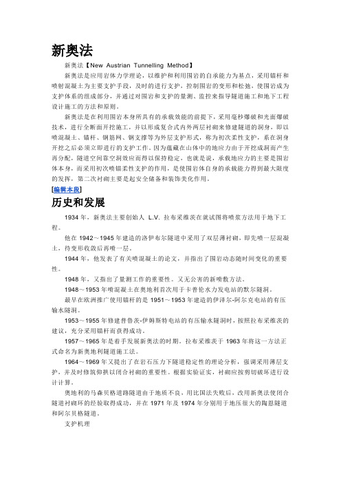
新奥法新奥法【New Austrian Tunnelling Method】新奥法是应用岩体力学理论,以维护和利用围岩的自承能力为基点,采用锚杆和喷射混凝土为主要支护手段,及时的进行支护,控制围岩的变形和松弛,使围岩成为支护体系的组成部分,并通过对围岩和支护的量测、监控来指导隧道施工和地下工程设计施工的方法和原则。
新奥法是在利用围岩本身所具有的承载效能的前提下,采用毫秒爆破和光面爆破技术,进行全断面开挖施工,并以形成复合式内外两层衬砌来修建隧道的洞身,即以喷混凝土、锚杆、钢筋网、钢支撑等为外层支护形式,称为初次柔性支护,系在洞身开挖之后必须立即进行的支护工作。
因为蕴藏在山体中的地应力由于开挖成洞而产生再分配,隧道空间靠空洞效应而得以保持稳定,也就是说,承载地应力的主要是围岩体本身,而采用初次喷锚柔性支护的作用,是使围岩体自身的承载能力得到最大限度的发挥,第二次衬砌主要是起安全储备和装饰美化作用。
[编辑本段]历史和发展1934年,新奥法主要创始人L.V. 拉布采维茨在就试图将喷浆方法用于地下工程。
他在1942~1945年建造的洛伊布尔隧道中采用了双层薄衬砌,即先喷一层混凝土,待变形收敛后再喷一层。
1944年,他发表了有关喷混凝土的论文,并指出了围岩动态随时间变化的重要性。
1948年,又指出了量测工作的重要性。
又无公害的新喷敷方法。
1948~1953年喷混凝土在奥地利首次用于卡普伦水力发电站的默尔隧洞。
最早在欧洲推广使用锚杆的是1951~1953年建造的伊泽尔-阿尔克电站的有压输水隧洞。
1953~1955年修建普鲁茨-伊姆斯特电站的有压输水隧洞时,按照拉布采维茨的建议,充分采用锚杆而获得成功。
1957~1965年是着手发展新奥法的时期。
拉布采维茨于1963年将这一方法正式命名为新奥地利隧道施工法。
1964~1969年又提出了在岩石压力下隧道稳定性的理论分析,强调采用薄层支护,并及时修筑仰拱以闭合衬砌的重要性。
浅谈新意法隧道施工理念及主要施工方法

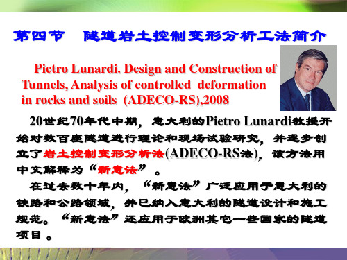
浅谈新意法隧道施工理念及主要施工方法摘要:新意法(NITM)即NewItalianTunnelingMethod,是40多年前意大利的PietroLunardi教授在围岩压力拱理论及新奥法理论研究的基础上,通过数百座隧道的结构分析和研究逐步创建出的岩土控制变形分析(ADECO-RS)法,它强调通过调节超前核心土的稳定性来控制隧道变形。
该工法被意大利公路、铁路领域广泛采用并纳入规范,且在欧洲许多国家的大型隧道施工项目中得到应用。
国内的卧龙隧道口、浏阳河隧道、桃树坪隧道等对新意法的部分要素进行了尝试,并取得了不错的效果。
本文主要分析新意法隧道施工理念及主要施工方法。
关键词:隧道施工;新意法;超前核心土;预支护引言在公路隧道建设中,为了方便公路桥梁与隧道的连接,保持线路线性平稳,高架桥连接的隧道经常采用多拱形隧道的设计形式。
连拱隧道具有位置选择自由和对地形适应性强的特点。
特别是在应用于城市时,门户电线的地板面积小,布线的复杂性小,可以大大降低拆除和设计成本。
然而,连拱隧道虽然具有上述优点,但也存在复杂的结构应力、许多施工工艺、结构系统频繁的应力转换、复杂的施工、缓慢的施工进度等缺点。
1、新意法核心理念新意法认为隧道围岩的变形分为收敛变形、预收敛变形及掌子面挤出变形。
因预收敛变形及掌子面挤出变形均取决于超前核心土的强度及变形特性,进而得出超前核心土的特性对整个隧道的围岩变形起关键作用。
新意法通过对隧道掌子面超前核心土岩体结构特性、岩体坚硬程度等特征判定将超前核心土稳定类型分为A、B、C三类,并将每种稳定类型与隧道整体变形情况对应关联。
当预测判定超前核心土为不稳定类型时,为了确保隧道安全穿越复杂地层,可以通过辅助手段将超前核心土加固至稳定类型,甚至依赖超前核心土,将其视为控制隧道围岩变形和稳定的重要工具,即提高超前核心土的刚度和强度就能够调整围岩预收敛及掌子面挤出变形的程度,达到围岩稳定的目的。
2、新意法主要内容2.1隧道围岩支护新方法的主要内容是预先保护隧道周围的岩石,主要是为了正确调整改良后的基性土的刚度和强度,实现对周围岩石变形的有效控制。
隧道工程资料:隧道施工新奥法.doc

隧道工程资料:隧道施工新奥法新奥法即新奥地利隧道施工方法的,原文是NewAustrianTunnellingMethod简称NATM,新奥法概念是奥地利学者拉布西维兹(L.V.RABCEWICZ)教授于50年代提出的,它是以隧道工程经验和岩体力学的理论为基础,将锚杆和喷射混凝土组合在一起作为主要支护手段的一种施工方法,经过一些国家的许多实践和理论研究,于60年代取得专利权并正式命名。
之后这个方法在西欧、北欧、美国和日本等许多地下工程中获得极为迅速发展,已成为现代隧道工程新技术标志之一。
六十年代NATM被介绍到我国,七十年代末八十年代初得到迅速发展。
至今,可以说在所有重点难点的地下工程中都离不开NATM。
新奥法几乎成为在软弱破碎围岩地段修筑隧道的一种基本方法。
新奥法是充分利用围岩的自承能力和开挖面的空间约束作用,采用锚杆和喷射混凝土为主要支护手段,对围岩进行加固,约束围岩的松弛和变形,并通过对围岩和支护的量测、监控,指导地下工程的设计施工。
新奥法(NATM)是新奥地利隧道施工方法的简称,在我国常把新奥法称为锚喷构筑法。
采用该方法修建地下隧道时,对地面干扰小,工程投资也相对较小,已经积累了比较成熟的施工经验,工程质量也可以得到较好的保证。
使用此方法进行施工时,对于岩石地层,可采用分步或全断面一次开挖,锚喷支护和锚喷支护复合衬砌,必要时可做二次衬砌;对于土质地层,一般需对地层进行加固后再开挖支护、衬砌,在有地下水的条件下必须降水后方可施工。
新奥法广泛应用于山岭隧道、城市地铁、地下贮库、地下厂房、矿山巷道等地下工程。
当前,世界范围内应用新奥法设计与施工城市地铁工程取得了相当大的发展。
如智利的圣地亚哥新地铁线采用新奥法施工地铁车站,车站位于城市道路下7~9m,开挖面积230m2,相当于17m(宽)14m (高);我国自1987年在北京地铁首次采用新奥法施工复兴门车站及折返线工程,车站跨度达26m。
针对我国城市地下工程的特点和地质条件,新奥法经过多年的完善与发展,又开发了浅埋暗挖法这一新方法,与明挖法、盾构法相比较,由于它可以避免明挖法对地表的干扰性,而又较盾构法具有对地层较强的适应性和高度灵活性,因此目前广泛应用于城市地铁区间隧道、车站、地下过街道、地下停车场等工程,如根据新奥法的基本原理,采用群洞方案修建的广州地铁二号线越秀公园站及南京地铁一期工程南京火车站站,断面复杂多变的折返线工程、联络线工程也多采用新奥法。
- 1、下载文档前请自行甄别文档内容的完整性,平台不提供额外的编辑、内容补充、找答案等附加服务。
- 2、"仅部分预览"的文档,不可在线预览部分如存在完整性等问题,可反馈申请退款(可完整预览的文档不适用该条件!)。
- 3、如文档侵犯您的权益,请联系客服反馈,我们会尽快为您处理(人工客服工作时间:9:00-18:30)。
附录附录A:外文翻译新意法的设计与施工10.4施工期间监控量测系统的设计施工期间监控量测系统的设计,应基于量测阶段预期出现的变形现象的类型和大小。
由于掌子面稳定的重要性,所以当一个隧道设计工程师在设计一个监测系统时,他将拟定一项计划对掌子面核心土的应力应变进行监测并通过对其监测结果进行分析和预测,然后通过这些信息与诊断阶段和处治阶段的预测结构进行对比分析。
过程如下:• 在掌子面核心土稳定的条件下时(如围岩性质比较坚硬),工程施工就应该立即大致地对开挖面地层的弹性范围和变形影响进行监测,但是没有必要反复监测和使用的精密的监测仪器,一般是在监测特殊的地质环境出现局部失稳时(例如岩石滑坡或岩石脱落)或者是在围岩性质不连续和出现裂痕的方向平行于隧道轴向需要用到刚性材料时才会用到精密的监测仪器,以此来预防发生岩爆。
因此,在这样的情况下通常都会在隧道内每个100米设置系统量测站和监控量测站来达到要求。
• (围岩的粘性现象)掌子面核心土虽然可以短期稳定,而且围岩应力在弹塑性范围内,但变形发生会在后期发生,而且是不可忽略的量级。
所以设计工程师在施工中通过挤出量测站、主量测站、监控量测站(与隧道埋深有关)及系统量测站,对变形和应力的大小及发展趋势进行及时监测尤为重要。
对测量进行校准和完善,这是得到的必要资料的唯一方法,可以此来评估经开挖后掌子面核心土是否充分稳定。
其中各种类型的量测站安装使用的频率将取决于当地地理环境和地质构造特征。
还应该设置掌子面挤出变形的量测站,因为在整个施工中要随时预测掌子面前方地层发生大幅度的塑性变形或是通过它来选择开挖方式和调控稳定监测技术,这项工作最好在隧道开挖停止7天后进行。
如果超前核心土在这种情况下没有充分保护,在过去的许多经验证明其实,在施工中,由于开挖使围岩内部缺少大量岩体将会产生一系列导致隧道不稳定的因素。
挤出变形量测站最好在系统量测站安装后,错开四分之一洞径的距离,以便量测掌子面核心土两侧的三维变形。
最后,通常每隔20~40米监控量测站与系统监测站隔开设置监测阶段所使用的测量仪器滑动变形计滑动变形计是滑动测微计的经济版本,应用广泛,操作简单,坚固可靠。
尽管滑动测微计有更高的精度,但滑动变形计0.02毫米/米的精度是可以满足要求的,可以不必采用高精度的滑动测微计。
滑动测微计是由一系列外径32mm的PVC管(每节长3m)组成。
管和管之间用套管连接组装成一个整体。
每隔1m设一个探测点。
测管的现场安装需钻约56mm的钻孔,然后用膨胀水泥锚固。
探测器的安装是通过球形头,它可以在管内安装的沟槽自由滑动,量测过程也是这样的。
M0是指探头与测量点之间的距离,这个值经过机器从测量杆上不间断的传送到位于测量管外的位移传感器上。
随后的测量是探头和测量点之间的新的距离(M1),L0的位移ΔL是由M1与M0之间的差值求得。
这些测量线上位移的差值就使得变形沿测斜管分布,测量线上的总位移可以通过所有的变形计算出来。
• 在掌子面核心土不稳定的情况下时(如围岩性质比较松散),在施工阶段如果没有对开挖土体进行适当的控制和加固等超前约束的话,地层的变形就会慢慢变大而导致不稳定。
所以设计工程师就应该立即指定安装极为频繁的挤出变形量测站、主量测站、监控量测站和系统量测站(相隔10~20米)。
通常从围岩稳定状态到围岩失稳状态是很突然的而且变形量很小。
如果变形在工程施工中期出现小的特殊变化或是恶化都将会足以引起极其严重和不可逆转的变形,例如会导致掌子面核心土失稳和隧道洞身的塌陷,所以对掌子面的挤出变形的量测是至关重要的。
在实际施工中当应力—应变状况难以监控时,单是收敛变形是不足以保持围岩的变形效应基本都处于控制范围内以及防止隧道塌方的,这是因为收敛变形处于整个变形过程的最后阶段,因此就出现无法控制的现象,这是隧道洞身周围岩体发生塑性变形的结果。
众所周知,塑性变形一旦明显以后就难以控制。
另一方面,掌子面的挤出变形是整个变形过程的第一阶段,如果经过妥善的监测的话,它将会出现大量的预收敛变形和收敛变形的现象,但是不会出现隧道塌方的现象,因为它有充足的时间来给隧道进行支护和加固等。
监测必须认真地按照具体情况执行。
例如当隧道内某区段受大型构造断裂带影响时,可能会遇到各种不同性质的材料和施工组织的混乱等情况,这种情况有时是难以预测。
在这种情形下,材料的地质力学预测是十分困难的,尤其是材料的变形性能。
模拟计算会变得很困难,只能通过精密仪器量测开挖期间和开挖后的变形的类型和大小。
了解地层压力张量也是十分有益的,或者是简单的水平与竖直压力的比例,通常是其中一个压力更大而使结构受力不均。
这时必须安装监控量测站进行隧道周边变形的量测,围岩内部位移的量测,以及围岩内部应力的量测,为了确定是否残余应力起作用。
这可以根据隧道承受的荷载情况确定是安装主量测站还是监控量测站。
如果在可能发生围岩滑坡的地方出现了破裂面或断层时,最好的方法是在围岩各个方向个不连续性处将测量器具综合使用。
然后工程师根据特殊的地理环境和地质情况等因素选择测量器械的种类、数量和测量位置。
在构造作用强烈的地区,水文地质量测是非常重要的。
因为岩性往往在水的渗透以及压力作用下将会方生急剧变化。
如果没有得到迅速的控制,强大水力梯度可能会严重影响隧道长期和短期稳定性。
监测阶段所使用的量测仪器磁力变形计磁力变形计主要广泛应用于测量施工期间道路路基的垂直沉降位移和大坝的水平位移。
它由一对受保护的波纹外套管保护着的检查管组成, (测量点)每隔一定的距离加上金属磁圈。
当检查管插入到钻孔内时,金属磁圈就固定到地层中了。
测量工作是将一个探头滑入检查管内测量金属磁圈的位置,因此在各个测量点就产生了位移。
磁力变形计每个金属磁圈的精确度可以达到± 1毫米左右,如果该测量精度达不到的话也要满足整个测量工作以及掌子面核心土的挤出变形的要求。
隧道开挖在遇到地下水层时对水的截断是非常重要的,所以要在衬砌后修输水渠道,然后进行系统地分析和测量排水流量。
必须弄清楚测压水位变化与弹簧两者在隧道附近产生影响之间的关系。
为了建立一个更为贴近实际而且能更好地评估在含水层隧道中排水设备所产生长期影响的水文地质模型,设计工程师也必须监控隧道浅埋段产生的围岩变形以及测量由于隧道开挖深度和水平地面沉降而引起的变形。
无论测量的结果是什么,对隧道在穿越下表结构时的施工都特别的重要,例如道路、建筑物或是当在河床下进行开挖工作时。
再者,表层结构本身就需要适当的仪器对其监测(表面测角器、不均匀沉降压力表等),通过监测来验证它的原始状况没有变化(绝对沉降和差异沉降监测、监测所有裂缝开放及受振动造成的影响等)。
在做好这些后对水文地质情况的监测也要必须进行,在监控隧道如何排除地表水流,并确保在隧道施工中不会出现任何静电干扰和安全问题上的监测工作是不可或缺的。
在隧道位于城市地区有可能毁坏一些基础设施时,设计工程师将更注重所有具有实用功能的基础设施。
由于地下隧道的通过甚至可能会导致下水道和天然气的泄漏而形成渡槽引起巨大的危险,高压电力线路也会因为受轻微的扰动将不再工作。
在这方面使用一个综合监测系统将是不可缺少的,以便交叉测量与数据重复处理能够同时进行,以消除或至少大大减少了因潜在的不准确的测量误差所产生错误的可能性。
10.5 隧道在使用时的监测如果该地下工程具有巨大的价值或者可能对周边环境产生正面或负面的影响时,就必须对其安全性和产生的效果进行清晰连续的监测,这项工作的持续时间应该是施工后和其整个使用寿命时间范围内。
在几年前这种类型的监测不是很常见,部分原因是在监测中可能要中断工程的使用以便给维修人员时间来采取必要的测量。
但是今天,远程遥控自动装置可以测量到关于监测该地下建筑可以正常运行的很多参数。
这就意味着一个监测系统可以在施工期间被使用,就能够在多年后还能继续提供数据来保证隧道不受外界影响以及隧道的正常使用。
根据隧道的情况在施工时结合现代化的最新信息这种方法使用以后,对地面结构体系的应力应变作用就有了足够的认识,在工程维护和修理的问题上就可以用科学的方法来解决。
检测阶段所使用的测量工具单点和多点式位移计单点和多点式位移计是用来测量地层沿钻孔轴线方向的移动,以此来保证洞口处不同深度测量点的数量。
是选用单点或是多点位移计取决于它安装的测量点的数量。
单点式位移计使用时需要一个有直径约4.5厘米的钻孔,而多点式位移计则需要一个直径约10厘米的钻孔。
它们都是用于测量隧道洞室周围岩体的变形。
该系统的组成是在地层中钻孔安装锚杆通过钢丝与地表相连接,殷钢和玻璃纤维杆受高强的润滑剂外壳保护。
因为殷钢的膨胀系数即大约高于普通钢的十分之一,所以在预计温度将要发生大幅度变化时选用殷钢更好。
玻璃纤维杆因为其实用性现在已经被广泛推广(它的伸长量可达到为准备安装的基本的折叠),但是当该测点的安装长度大于70 - 80米它不能用于测量收缩量。
玻璃纤维杆可以在保护壳内锚杆点与位移计口之间自由滑动,而它的每一次动作都将被数值比较器或电位仪传感器测量记录下来。
施工期间大部分用于监测的的仪器将被安装在测量站,其目的是提到监控量测的质量。
尤其是,如果在隧道的使用中采用解释的测量,与类似的测量直进行接比较的的话更容易理解和更有意义。
显然这些需要仔细监测服的隧道在使用时最务时将会因为一些随时间变化不稳定因素而受到影响。
例如发生隧道滑坡和严重的tectonised,或是在任何情况下受到大量粘性和徐变现象等。
对于浅埋隧道洞口段的施工方法应在整个施工工作中进行监测,因为由于周围环境任何时候的大幅扰动它将受到影响(如地震活动的结果),即使建设完成以后也一样。
那哪个才是隧道在运行时最合适的测量呢?在回答这个问题之前我们必须明确一个长期的监测目的。
它必须要做到以下几点:• 核实监测的作用,要知道所有的监测行为是为了确保地下洞室的稳定性和完整性,是工程设计活得符合规定的安全系数的保证。
• 给建筑对周围环境的影响进行监测和评估, 特别重视早已存在的水文地质环境的均衡性(监测范围应包括由于地表水位下降可能会使农作业土壤肥力减少或者是在它包含有害物质溶液或悬浮液时存在排水困难现象等潜在的危害)。
因此对于隧道使用时的监测应包括获得一些关于隧道洞身周围水文地质条件的变化和稳定器械应力——应变状态发生改变的数据。
该仪器在施工阶段就已经安装上而不可缺少,可直接测量在初期支护和二次衬砌时的压力分布。
设计工程师应该注意那些通常有数据模型预测不了的,特别是以前就存在地应力状态可能出现的不对称荷载。
收敛变形的量测在监测工作中占有重要的地位,它包括对衬砌内部轮廓的基本测量以及查明它不会随时间发生变形(即检查隧道断面是否会变成椭圆形)。
一般来说测距计、收敛钉和地形指标通常都可以满足这种类型的测量,但是这些系统必须保证对隧道的运行产生的影响很小甚至没有,比如雷达或电视等都可在特定情况下使用。