MIK-LCLY轮辐式拉压力传感器
亚克勒夫GC35数字压力传感器用户说明书

PIP #: TR-PI-105Applicable to:GC35PROGRAMMING PLANT AIR LINE PRESSURE CONTROL ON THE GC35 INDICATING PRESSURE TRANSMITTERThe GC35 Digital Pressure Transmitter is compact and flexible with many usages. It can be easily programmed to monitor and control plant air line pressure. The GC 35 can be acquired with many different ranges but for this application a transmitter with 0 to 150 psi range shall be selected, 4-20 mA analog output, and one switch PNP.Figure 1 - GC35 Pressure TransmitterPlant Line Compressor Pressure Control Example:This example demonstrates the control of a plant air line compressor application with a full loaddischarge pressure of 100 psi and an unload discharge pressure of 110 psig by controlling the 4-20 mA output signal with a programmable regulator. Also, to shut down the compressor and activate an audible warning alarm if line pressure exceeds 115 psi by using an external relay normally opened to turn on the audible alarm and normally closed to shut down the compressor.Figure 2 – GC35 Pressure Transducer Installation ExampleInstallation:Connect transmitter, analog output, compressor shutdown and audible warning buzzer switches per application, diagrams below and manual instructions.Figure 3 – GC35 Pressure Transducer WiringFigure 4 – GC35 Pressure Transducer Switch and Analog Output WiringCOMPRESSED AIRPlant Line Compressor Pressure Control Settings Method:Procedure to program the GC35 transmitter to control plant air line pressure. Offset analog output from 0 psi to 100 psi. That, is 66.7 % of full range corresponding to 100 psi (4 mA). Scale down the upper range from 150 psi to 110 psi. 73.3% of full scale is equivalent to 110 psi (20 mA). Subsequently, set switches set point and dead bands.GC35 Transmitter Function Setting Method:∙ Press and hold MODE button for more than three seconds to get into program mode.∙ Press UP or Down arrow to make changes.∙ Press and release MODE button to select changes and to walk through the menu.∙ Continue to step-1 after power-on message.∙ Press and hold MODE button for more than three seconds to return tomeasuring mode.Step 1∙ CAP To select hysteresis (HYS) or Window comparator (yin). ∙ Select HYS to control analog output. ∙ Press UP or Down arrow to display HYS.∙ Press and release MODE button to select and move to the next step.Step 2∙ oPC To select switch type (NPN or PNP).∙ It is a matter of preference. PNP switch shall be used for thisapplication.∙ Press UP or Down arrow to display PNP.∙ Press and release MODE button to select and move to the next step.Step 3∙ FiL To enter filter selection. Filter selection, there are five filterselections (F1 to F5).∙ Use the filter function to improve analog output and difficult to readdisplay if pressure oscillates.∙ Press UP or Down arrow until F1 is displayed (pressure fluctuation isnot anticipated).∙ Press and release MODE button to select and move to the next step.Step 4∙ ECo To turn ON or OFF power saver.∙ Press Up or Down arrow until EoF is displayed (power saver off). ∙ Press and release MODE button to select and move to the next step.Step 5∙ LrG To select ring LED light. There are two options Lr0 to turn off ringlight or Lr1 to turn on ring light.∙ Press Up or Down arrow until Lr1 is display.∙ Press and release MODE button to select and move to the next step.Step 6∙ Uni To select units (arbitrary or psi).∙ Press Up or Down arrow until PSI is displayed.∙ Press and release MODE button to select and move to the next step.Step 7∙ A-L To enter analog output zero reference corresponding to 4 mA. ∙ The operational range is from 100 to 110 psi. Therefore, set 100 psias the zero reference 4 mA analog output (66.7% of full range). ∙ Press Up or Down arrow until 66.7 is displayed.∙ Press and release MODE button to select and move to the next step.Step 8∙ A-H To enter span analog output reference corresponding to 20 mA. ∙ The operational range is from 100 to 110 psi. Therefore, set 110 psias the span 20 mA analog output (73.3% of full range). ∙ Press UP or Down arrow until 73.3 is displayed.∙ Press and release MODE button to select and move to the next step.GC35 Transmitter Switch Set Point and Dead Band Settings Method:∙ Press and hold MODE button less than three seconds to get into program mode.∙ Press UP or Down arrow to make changes.∙ Press and release MODE button to select changes and to move to the next step.∙ Continue to step-1 after once in program mode.∙ Press and hold MODE button for more than three seconds to return to measuring mode.Step 1∙ US1 To select in use (USE) or not in use (noU).∙ Press UP or Down until USE is displayed to configure output switch. ∙ Press and release MODE button to select and move to the next step.Step 2∙ A1 To enter output 1 switch set point. ∙ Set switch to change state at 115 psi. ∙ Press UP or Down until 115.0 is displayed.∙Press and release MODE button to select and move to the next step.Step 3∙ B1 To enter dead band.∙ Set 5 psi dead band to deactivate at 110 psi. ∙ Press UP or Down until 5.0 is displayed.∙Press and release MODE button to select and move to the next step.Step 4∙ On1 To delay switch turn on.∙ Delay switch turn on shall not be used for this application. ∙ Press Up or Down arrow until 0.00 is displayed.∙ Press and release MODE button to select and move to the next step.Step 5∙ OF1 To delay switch turn off.∙ Delay switch turn off shall not be used for this application. ∙ Press Up or Down arrow until 0.00 is displayed.∙Press and release MODE button to select and move to the next step.Step 6∙ SAv To save set point, dead band, and on/off time delay. ∙Set point, dead band, and on/off time delay can be stored onstorage S-1 or S-2 (save set point, dead band, and on/off time delay on S1).∙ Press UP or Down arrow until S-1 is displayed.∙ Press and release MODE button to select and move to the next step.Step7∙Lod To load set point, dead band, and on/off time delay.∙Load set point, dead band, and on/off time delay can store onstorage L-1 or L-2 (load set point, dead band, and on/off timedelayonL1).∙Press UP or Down arrow until L-1 is displayed.∙Press and release MODE button to select and move to the next step.Step8∙LoP Loop check mode allows program and analog output verificationwith the transmitter pressurized or non-pressurized. It simulates theprocess and allows for troubleshooting.∙Press Up or Down arrow to simulate pressure values.∙After verification press and hold MODE button for more than threeseconds to return to measuring mode.Function Verification:The GC35 loop-check allows program, switch and analog output verification with the transmitterpressurized or non-pressurized.Analog Output Test:Confirm analog output wiring per figure 3 and 4 diagrams or installation and maintenance instructions.Analog output can be tested during loop check mode or measurement mode. Change loop check value or apply equivalent pressure to test the analog output (see results below for reference).∙Connect amp-meter per manual instructionsor diagram above.∙Press the Up or Down arrow until 100.0 isdisplayed or apply 100 psi.∙Verify amp meter reading (4.00 mA).∙100 psi corresponds to 0% FS analog signal(4 mA at 100 psi).Switching Verification:Ensure switch wiring per figure 3 and 4 diagrams or installation & maintenance instructions. Switch verification can be tested during measurement mode or loop check. Change loop check value or apply equivalent pressures (see results below for reference).∙Press the Up or Down arrow until 105.0 isdisplayed or apply 105 psi.∙Verify amp meter reading (12.00 mA).∙105 psi corresponds to 50% FS analog signal(12 mA at 105 psi).∙Press the Up arrow until 110.0 is displayedor apply 110 psi.∙Verify amp meter reading (20.0 mA).∙110 psi corresponds to 100% FS analogsignal (20 mA at 110 psi).∙ A 290 ohms resistor shall be use as theswitch load to verify switch. Wire switch permanual instructions or figure above.∙Press the Up or Down arrow until 100.0 isdisplayed or apply 100 psi.∙Switch is in normal state (OFF)∙Place voltmeter leads across resistor and verify voltage reading (0 V dc).∙Press the Up arrow until 115.0 is displayed or increase pressure up to 115 psi.∙Switch turns ON.∙Verify voltmeter reading (28 VDC).∙External relay energizes.∙Relay normally closed switch opens - compressor shuts down.∙Relay normally open closes - audible alarm turns ON.∙Press the Down arrow until 110.0 is displayed or decrease pressure to 110 psi. ∙Verify voltage reading (0 V dc).∙Switch changes to normal state (OFF).。
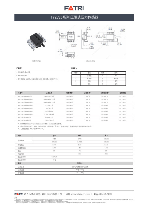
西人马TYZV26系列压阻式压力传感器说明书
声明西人马致力于遵守中国政府颁布的所有与公司经营相关的出口管制法律法规和包括美国在内的国际相关的出口管制法律法规。
当您购买或接收西人马产品时,您应保证所有西人马产品的购买,销售以及应用或使用过程中,均符合中国政府,所在国家政府以及联合国决议的所有相关要求。
您保证不会违反任何联合国、美国、欧盟或任何其他适用的禁运法律直接或间接地出口、再出口或转移或转运至或经过任何禁制国家。
您应保证不会将西人马产品直接用于,或转售于第三方等方式,将该产品用于核、生物或化学武器,或者能发射该武器的导弹等用途。
由于产品版本升级或其他原因,本手册内容会不定期进行更新。
除非另有约定,本手册仅作为使用指导,本文档中的所有陈述,信息和建议不构成任何明示或暗示的担保。
在法律允许的范围内,本手册的最终解释权归西人马所有。
网址: 西人马联合测控( 泉州 )科技有限公司电话:400-678-5081Model:TYZV26产品号工作压力TYZV26-500-000-230TYZV26-1000-000-230TYZV26-2500-000-230TYZV26-5000-000-210TYZV26-5000-000-230TYZV26-7500-000-210TYZV26-7500-000-230TYZV26-10-000-010TYZV26-10-000-0301、综合精度包括在25℃下测试的压力非线性、压力迟滞和重复性。
2、总误差带包括零位、量程、压力非线性、压力迟滞、重复性、热零点偏移、热量程偏移和热迟滞造成的偏差。
3、长期稳定性在25℃下测试1000小时。
-500~500 Pa d-1000~1000 Pa d -2500~2500 Pa d 0 ~ 5 kPa d -5~5 kPa d0 ~7.5 kPa d-7.5 ~7.5 kPa d 0~10 kPa d-10~10 kPa d ±0.25%FS ±0.25%FS ±0.25%FS ±0.25%FS ±0.25%FS ±0.25%FS ±0.25%FS ±0.25%FS ±0.25%FS±2%FS ±2%FS ±2%FS ±1%FS ±1%FS ±1%FS ±1%FS ±1%FS ±1%FS±0.5%FS ±0.5%FS ±0.5%FS±0.35%FS ±0.35%FS ±0.35%FS ±0.35%FS ±0.35%FS ±0.35%FS -20℃~85℃-20℃~85℃-20℃~85℃-20℃~85℃-20℃~85℃-20℃~85℃-20℃~85℃-20℃~85℃-20℃~85℃长期稳定性3总误差带2综合精度1温度补偿其他TYZV26工作介质工作温度存储温度非导电气体和非导电液体-40℃~+85℃-40~+125℃零位输出满量程输出输出响应时间输出分辨率输出分辨率0.49V 3.99V I 2C0.03%FS 16位0.5V 4VI 2C1ms0.51V 4.01V I 2C2msSize(Unit: mm)产品特性自带校准及温度补偿 模拟数字双输出用于呼吸机、麻醉机、制氧机和其它体外诊断设备,也可用于HVAC针脚定义1234接地端电源端SDA SCL 引脚5678N/C输出端N/C N/C 引脚定义定义。
轮辐式压力传感器
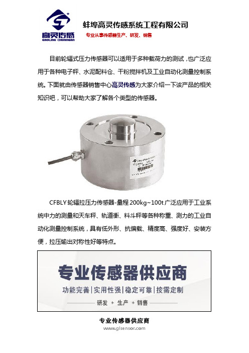
目前轮辐式压力传感器可以适用于多种载荷力的测试,也广泛应用于各种电子秤、水泥配料仓、干粉搅拌机及工业自动化测量控制系统。
下面就由传感器销售中心高灵传感为大家介绍一下该产品的相关知识吧,可以帮助大家了解各个类型的传感器。
CFBLY轮辐拉压力传感器-量程200kg~100t广泛应用于工业系统中力的测量和天车秤、轨道衡、料斗秤等各种称重、测力的工业自动化测量控制系统,具有低外形、抗偏载、精度高、强度好、安装方便,拉压输出对称性好等特点。
目前在市场上常见的轮辐传感器的量程型号如下图展示:
以下是轮辐传感器的主要技术参数,可以帮助大家了解这款产品使用情况,以便能正常使用。
蚌埠高灵传感系统工程有限公司在自主创新的基础上开发生产出力敏系列各类传感器上百个品种,各种应用仪器仪表和系统,以及各种起重机械超载保护装置,可以广泛应用于油田、化工、汽车、起重机械、建设、建材、机械加工、热电、军工、交通等领域。
公司除大规模生产各种规格的高精度、高稳定性、高可靠性常规产品外,还可根据用户具体要求设计特殊的非标传感器,以满足用户的特殊要求。
如果您想进一步的了解,可以直接点击官网高灵传感进行在线了解。
轮辐式拉压力传感器
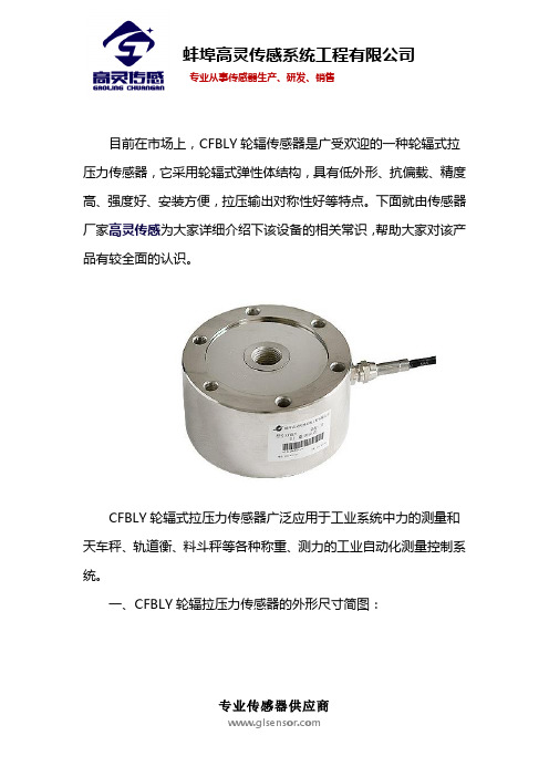
目前在市场上,CFBLY轮辐传感器是广受欢迎的一种轮辐式拉压力传感器,它采用轮辐式弹性体结构,具有低外形、抗偏载、精度高、强度好、安装方便,拉压输出对称性好等特点。
下面就由传感器厂家高灵传感为大家详细介绍下该设备的相关常识,帮助大家对该产品有较全面的认识。
CFBLY轮辐式拉压力传感器广泛应用于工业系统中力的测量和天车秤、轨道衡、料斗秤等各种称重、测力的工业自动化测量控制系统。
一、CFBLY轮辐拉压力传感器的外形尺寸简图:
二、CFBLY轮辐拉压力传感器重要的技术指标,如下图:
蚌埠高灵传感系统工程有限公司在自主创新的基础上开发生产出力敏系列各类传感器上百个品种,各种应用仪器仪表和系统,以及各种起重机械超载保护装置,可以广泛应用于油田、化工、汽车、起重机械、建设、建材、机械加工、热电、军工、交通等领域。
公司除大规模生产各种规格的高精度、高稳定性、高可靠性常规产品外,还可根据用户具体要求设计特殊的非标传感器,以满足用户的特殊要求。
如果您想进一步的了解,可以直接点击官网高灵传感进行在线了解。
Rolls-Royce 连续气动压力监测系统 - CPM 系统说明书

Cylinder Pressure Monitoring (CPM) For peak performance and improved reliabilityOptimizing equipment reliability and lifecycle costs are key requirements for operating a power plant profitably. That’s why, in addition to developing new products that meet improved performance targets, we also focus on optimizing the performance of our legacy equipment operating in the field-generator sets that are built to run for decades. For you that means continuous improvements, and genuine confidence that your equipment will always achieve its full potential.Available for all medium speed gas engines from Rolls-Royce, the continuous cylinder pressure monitoring (CPM) system stabilizes engine performance, significantly improving its reliability while also protecting it from excessive stress. The Otto-cycle combustion process used in medium speed gas engines allows for minor variance in firing pressures without any noticeable consequences for the operation. However, optimizing the engine’s combustion pressure levels with CPM results in exceptionally smooth and stable operation. This is achieved through continuous alignment of the combustion pressures thanks to an automatic monitoring and adjustment process.A wide range of real-time combustion data iscontinuously monitored by sensors installed in each combustion chamber. This data is analysed and used as a basis for optimization, including adjustment of the ignition angle, to ensure automatic alignment of firing pressures across all cylinders. As a result,Improve equipment reliability by aligning cylinder pressures Protect your equipment and reducelifecycle costsequipment efficiency and fuel consumption are optimized. Operational experience with CPM has shown a reduction in fuel consumption of up to 2% depending on the current tuning of the engine. Smoother operation increases overall equipment safety and component life. And protecting it from excessive vibrations due to misfiring, knocking and mechanical or thermal overload helps improve its reliability while reducing unscheduled stops.As a result of the stabilized combustion pressures, emissions are contained at the design level. Emissions and efficiency can be further optimized with an automatic NOx control upgrade (if not already fitted) available for gas engines.In addition to the peak firing pressure control, CPM also includes the following protection and monitoring functions:• High pressure detection • Knock detection • Misfire detection• Detection of thermal overload in cylinders • Condition monitoring of the cylindersAll the above functions are shown on the CPM touch screen with an indication of the affected cylinder(s).An intelligent system for smootherengine operationApplicable installationsOperation and maintenanceAll CPM system alarms are displayed on the CPM touch screen, and can also be integrated in the plant’s SCADA (Supervisory Control And Data Acquisition).As the CPM is an automated system, special attention is not necessary to keep it functioning properly. To ensure prompt detection of performance issues or other irregularities requiring attention, a simple daily monitoring routine is all that’s required.The intelligent system simplifies daily operation and provides increased visibility into the condition of the systems combustion components, helping you time service activities appropriately and avoid unscheduled stops.By measuring all cylinder pressures simultaneously, CPM enables the engine tuning process to be completed more quickly after service, reducing plant downtime significantly.In addition to normal spread variance in firing pressure, increased instability comes from several other factors. Over time, minor drifting of gas valves, spark plugs, pre-chamber valves and other combustion components may occur.Additionally, the manual demands of traditional measurement of cylinder pressure, when combined with any deviation from original factory settings, will affect the engine’s performance and stability.Manual ignition tuning is generally done after every main overhaul, whereas CPM continuously makes the adjustments automatically, in parallel on all cylinders, ensuring a more accurate result.© Bergen Engines AS 2017The information in this document is the property of Bergen Engines AS and may not be copied, or communicated to a third party, or used, for any purpose other than for which it is supplied without the expressed written consent of Bergen Engines AS.Bergen Engines ASA Rolls-Royce Power Systems CompanyPO Box 329 Sentrum, N-5804 Bergen, Norway /bergen ******************************。
SICK, Inc. 高温应用下压力传感器和开关安装指南说明书

Extend Pressure Measurement into High Temperature ApplicationsIntroductionMeasurement of pressure plays a central role in many areas of a plant, in the manufacturing industry, in machine tooling, in process engineering, and in the manufacture and processing of food andbeverages. Pressure measurement in industrial applications typically occurs with the help of pressure transmitters and switches. Pressure transmitters deliver a continuous current or voltage signal proportional to the pressure applied. Pressure switches are used to monitor pressure. Electronic pressure switches are characterized by their digital switching outputs, which are activated or deactivated when the defined, programmable threshold levels have been reached.Monitoring, measuring, and controlling pressure can be tricky if the process temperature exceeds the limits of the pressure instrumentation, such as pressure transmitters and switches. It is possible to obtain an accurate pressure measurement using standard pressure transmitters in these high temperature applications. The trick is to ensure that the process is cooled before reaching the pressure measuring device.There are generally two different methods used to protect the pressure transmitter and/or the pressure switch from high temperatures. These two proven methods are done through the use of coolingelements and standoff piping. Provided below are guidelines on how to protect the pressure devices from extreme temperatures using cooling elements and standoff piping.Cooling ElementsA cooling element is an accessory that puts some distance between the transmitter and the heat of the process. There are often times “fins” that allow for air circulation for betterheat dissipation. Cooling elements are designed to cool the process to a temperature that is within the specifications of the pressure transmitter.Cooling elements are a great way to protect the transmitter from high temperature processes. Cooling elements act as a heat sink, which cools the process before it reaches the transmitter.Cooling elements can extend the maximum process temperature of pressure transmitters from 185 °F (85 °C) up to 392 °F (200 °C).Figure 1: Cooling element.Figure 2: Cooling element attached to PBS Pressure Transmitter, Switch, and Display.Cooling elements from SICK provide heat protection as shown in the tables below. For the PBS electronic pressure switch, pressure transmitter and display; cooling elements can protect within the following guidelines:Chart 1: Temperature range of PBS pressure transmitter, switch, and display when installed with a cooling element (°F).PBS maximum process temperature when installed without a cooling element is 185 °F.For the PBS electronic pressure switch, pressure transmitter and display; cooling elements can protect within the following guidelines:Chart 2: Temperature range of PBS pressure transmitter, switch, and display when installed with a cooling element (°C).PBS maximum process temperature when installed without a cooling element is 85 °C.Chart 3: Temperature range of PFT pressure transmitter when installed with a cooling element (°F).PFT maximum process temperature when installed without a cooling element is 212 °F.For the PFT pressure transmitter; cooling elements can protect within the following guidelines:Chart 4:Temperature range of PFT pressure transmitter when installed with a cooling element (°C).PFT maximum process temperature when installed without a cooling element is 100 °C.Chart 5: Temperature range of PBT pressure transmitter when installed with a cooling element (°F).PBT maximum process temperature when installed without a cooling element is 176 °F.For the PBT pressure transmitter; cooling elements can protect within the following guidelines:Chart 6: Temperature range of PBT pressure transmitter when installed with a cooling element (°C).PBT maximum process temperature when installed without a cooling element is 80 °C.If cooling elements do not provide enough cooling to meet the application, standoff piping / impulse lines may be used.Standoff PipingUsing standoff piping (otherwise known as impulse lines) cools the process before it comes in contact with the pressure transmitter. Standoff piping may also allow the user to relocate the transmitter to a more convenient location for maintenance.Impulse line lengths are calculated using a general rule of thumb. For every 100 °F that the temperature needs to drop, users need to have 1 foot of impulse lines. For instance the maximum process temperature specification of the PBS pressure transmitter, switch, and display is 185 ° F (85 °C). If the process temperature is 585 °F, the process would have to be cooled 400 °F to be within the transmitter specification (585 - 185 = 400). Where 585 is the process temperature in °F, 180 is the maximum process temperature of the PBS, and 400 is the decrease in the temperate required for the transmitter. Dropping the process temperature by 400 °F is easily done using a minimum of 4 feet of impulse lines. This is a general rule of thumb, assuming a 68 °F (20 °C) ambient temperature. For higher ambient temperatures, longer impulse lines are required. For lower ambient temperatures, shorter impulse lines are required. Also, most users add a little more pipe length for added peace of mind.If the impulse lines are too long, other problems may present themselves:•Damping of the pressure signal•Blockage of the pressure signal•Leakage at couplingsTherefore, a balance between just long enough and too long must be achieved. Piping diameters should be as follows:Type of measured fluidImpulse Line Length0-52.5 ft (0-16 m) 52.5-148 ft (16-45 m) 148-295 ft (45-90 m)Water/steam and dryair/gas0.27-0.35 in (7-9 mm) 0.4 in (10 mm) 0.51 in (13 mm) Wet air/wet gas 0.51 in (13 mm) 0.51 in (13 mm) 0.51 in (13 mm) Oils of low mediumviscosity0.51 in (13 mm) 0.75 in (19 mm) 0.98 in (25 mm) Very dirty fluids 0.98 in (25 mm) 0.98 in (25 mm) 1.50 in (38 mm)Table 1: Impulse line diameters from ISO2186:1973Type of metered fluid Impulse Line Length0-52.5 ft (0-16 m) 52.5-148 ft (16-45 m) Water/steam and dry air/gas0.27-0.35 in (7-9 mm) 0.4 in (10 mm) Wet air/wet gas 0.51 in (13 mm) 0.51 in (13 mm) Oils of low medium viscosity0.51 in (13 mm) 0.75 in (19 mm) Very dirty fluids0.98 in (25 mm)0.98 in (25 mm)Table 2: Impulse line diameters from ISO/CD 2186:2004Gas ApplicationsMount hardware upward to allow moisture to drain out and not fill the impulse piping:• Slope impulse piping at least one inch per foot(8 centimeters per meter) downward from the transmitter toward the process connection.Liquid ApplicationsMount hardware downward to allow the escape of trapped vapor in the impulse piping:• Slope impulse piping at least one inch per foot(8 centimeters per meter) upward from the transmitter toward the process connection. • Vent all gas from the liquid piping legs.• Prevent sediment deposits in the impulse piping.ConclusionThere are generally two different methods used to protect the pressure transmitter and/or the pressure switch from high temperatures. These two proven methods are cooling elements and standoff piping. Some of the time a combination of both methods is used to give the engineer added peace of mind. By using either method, a standard pressure transmitter and/or pressure switch may be used in high temperature applications.Figure 4: Mounting hardware for liquid applications.Figure 3: Mounting hardware for gas applications.。
维萨拉 DRYCAP 传感器技术系列产品说明书

无论您的应用范围是什么,您都会从维萨拉产品组合中找到适合的露点仪。所有维 萨拉传感器均能耐受污染物,如水溅、环境湿度、压缩机油和化学杂质。
每款产品的测量范围
Optimal measurement range for each product
手Ha持nd式-露he点ld和de温w度p仪oi表nt and temperature meter
关于
维萨拉
参考编号 B212711ZH-A ©Vaisala 2023
维萨拉是一家环境和测量技术领域的设备生产商。凭借将近 90 年的经验,维萨拉为世界更美好而进行观测。我们是客户的可靠合 作伙伴,能够提供观测和测量产品及服务。维萨拉总部位于芬兰,在全球拥有超过 2,000 名专业人员,公司在纳斯达克赫尔辛基证 券交易所上市。
• 维萨拉第一台将露点和压力测量 相结合的变送器
• 与维萨拉手持式仪表 Indigo80 兼容,方便抽检、本地显示和数 据记录
• 压力高达 12 bar • DRYCAP® 和 BAROCAP®
传感器技术
• 测量范围可以低至 -80 °C • 压力高达 50 bar • DRYCAP® 传感器技术
4
相关产品
INDIGO80 手持式显示表头配 DMP80
适用于现场采样和校准、数据分析和诊断
访问 /compressedair 了解有关可用仪器和配件的更多信息。 如有任何问题,请随时与我们联系。
远程显示屏
连接电缆
• 露点测量范围宽 • 双探头、高精度便携式诊断和数据记录工具 • 行业标准 USB-C 接口 • 基于菜单的交互式多语言用户界面
IInnddigigoo8800w与ithDDMMPP8800
轮辐式拉压力传感器

轮辐式拉压力传感器有着突出的优点,分别是高度低、精度高、线性度好、抗偏心载荷及侧向力能力强。
它既可用于测量压力,也可用于测量拉力,因此特别适用于称重和测力之用。
下面就由传感器销售中心高灵传感为大家介绍一下该产品的相关知识吧。
量程200kg~100t的CFBLY轮辐拉压力传感器,是我们在工业系统中常见的轮辐式拉压力传感器,具有低外形、抗偏载、精度高、强度好、安装方便,拉压输出对称性好等优点。
1、市场上常见的轮辐传感器的量程型号如下图展示:
2、轮辐传感器的主要技术参数:
蚌埠高灵传感系统工程有限公司在自主创新的基础上开发生产出力敏系列各类传感器上百个品种,各种应用仪器仪表和系统,以及各种起重机械超载保护装置,可以广泛应用于油田、化工、汽车、起重机械、建设、建材、机械加工、热电、军工、交通等领域。
公司除大规模生产各种规格的高精度、高稳定性、高可靠性常规产品外,还可根据用户具体要求设计特殊的非标传感器,以满足用户的特殊要
求。
如果您想进一步的了解,可以直接点击官网高灵传感进行在线了解。