欧图II反馈抑制器用户手册
Omega 2-wire LCD 数字显示与控制单元用户指南说明书

e-mail:**************For latest product manuals:Shop online atMade in ChinaUser’s GuideTwo-wire Display and Control UnitOmega TX03 ManualManual for 2-w ire LCD displa y and control u nit1.BriefOmega series universal intelligent 2-wire LCD d igital display is fit for al l of the transmitters and converters with 4~20mA 2-wire technique, just as pressure, differential pre ssure, temperature, flow, PH, acceleration and so on.16 Bit ADC MCU insid e. Customer can use the three buttons to program thezero point, Span, unit, d ecimal point, damping a nd alarm point etc. inst ead of the potentiometer. The actual value will expressed by the schedule.And it can replace all of the analog indicators in the market2. feature1)High accuracy and stabi lity.2)16 Bit ADC MCU inside.3)The scope of the value c an be displayed on the L CD is -1.9.9.9.9. ~9.9.9.9.9.4)LCD can work at 3mA. Dropout voltage≤3.1V5)34 optional units.Many kinds of the valu e can be displayed, such aspressure, temperature, P H and so on.6)Friendly soft interface.7)The schedule show the value measured in real time, and it willtwinkle to alarm8)Two OPTO switch outpu ts,NPN, PNP output3. Setting“ M” menu item for setting“” to move the cursor“”to change the value that the cursor point to and move the decimal point.Omega TX03 Manual3.1 power onAfter the digital LCD display was connected to the current circle 4~20mA, LCD is lighted,the initial screen display the default setting:3.2 Zero-point (value to be displayed for 4mA)Press button “M” to enter zero-point setting mode: (Factory default setting is4.0000mA)→Press “” to move the cursor.→Press “” to change the value that the cursor point to.→When the cursor move to the first left number, press “” again, the decimal point is twinkling, press “” to move the decimal point.→Press “M” to confirm setting and return to the menu item3.3 Span (value to be displayed for 20mA)Press “M” to continue, span setting mode is displayed:(Factory default setting 20.000mA)→Press “” to move the cursor.→Press “” to change th e value that th e cursor point to.→When the cur sor move to t he first left n umber, press “” again, the decimal point will twinkle, press “” to move the decimal poin t.→Press “M” to confirm settin g and return t o the menu ite m3.4 Unit setti ngPress button “M” to continu e, unit setting mode is disp layed:→Press “” or “” to select the unit, For example “℃”is selected,unit is displayed o n the LCD.Optional unit s: V, mV, bar, mbar, P a, KPa, MPa, mH2O, mmH2O, cmH2O,℃o F, K, RH, VO L, PPM, mmHg, PSI, TOR, kg, g, N, KN, ,LEL, PH, m, cm, mm, INC H, M/S, Ohm, Kohm, %.3.5 Decimal d igitsPress button “M” to continu e, decimal dig its setting mo de is displaye d:→Press “” or “” to select the number of decimal digits, (Valid number: 0,1,2,3)3.6 DampingPress button “M” to continue, damping setting model is displayed:→Press “” to move the cursor.→Press “” to change the value that the cursor point to.Value is increased and decreased by step 0.1s. (Min=0s, Max=99.9s, step 0.1s) →“M” to confirm setting and return to the menu item.3.7 AlarmPress button “M” to continue, alarm setting mode is displayed:→Press “” or “” to change the setting either “ON” or “OFF”.“ON” means the setting parameter is available, and the alarm wasexpressed by the twinkle of the schedule on the top and the value. “OFF”means the alarm setting parameter is unavailable.3.8 The first alarm point.Press button “M” to continue, first alarm point setting mode is display:The method of setting is the same as step 3.23.9 The second alarm pointPress button “M” to continue, second alarm point setting mode is display:The method of setting is the same as step 3.23.10 The direction of the first alarm pintPress button “M” to cont inue, the dire ction of the f irst alarm po int setting m odeis displayed:Press “” or “”to change t he setting ei ther “UP” or “Down”. “U P”means alarm while the value is above the alarm parameter, and “Down”means alarm while value is below the alarm param eter.3.11 The dir ection of the first alarm pointPress button “M” to cont inue, the dire ction of the first alarm p int setting m odeis displayed:Other is the s ame as 3.10.3.12 The del ayPress button “M” to cont inue, delay s etting mode is display:→Setting is the same as 3.6 (Min=0s, Ma x=99.9s step 0.1)3.13 Display Mo dePress button “M” to cont inue, display mode settin g is display:Three displa y modes are for selection:Pressure, Cu rrent or Perc ent4 Dimension sIt is the policy of OMEGA Engineering, Inc. to comply with all worldwide safety and EMC/EMI regulations that apply. OMEGA is constantly pursuing certification of its products to the European New Approach Directives. OMEGA will add the CE mark to every appropriate device upon certification.The information contained in this document is believed to be correct, but OMEGA accepts no liability for any errors it contains, and reserves the right to alter specifications without notice.WARNING: These products are not designed for use in, and should not be used for, human applications.WARRANTY/DISCLAIMEROMEGA ENGINEERING, INC. warrants this unit to be free of defects in materials and workmanship for a period of 13 months from date of purchase. OMEGA’s WARRANTY adds an additional one (1) month grace period to the normal one (1) year product warranty to cover handling and shipping time. This ensures that OMEGA’s customers receive maximum coverage on each product.If the unit malfunctions, it must be returned to the factory for evaluation. OMEGA’s Customer Service Department will issue an Authorized Return (AR) number immediately upon phone or written request. Upon examination by OMEGA, if the unit is found to be defective, it will be repaired or replaced at no charge. OMEGA’s WARRANTY does not apply to defects resulting from any action of the purchaser, including but not limited to mishandling, improper interfacing, operation outside of design limits, improper repair, or unauthorized modification.This WARRANTY is VOID if the unit shows evidence of having been tampered with or shows evidence of having been damaged as a result of excessive corrosion; or current, heat, moisture or vibration; improper specification; misapplication; misuse or other operating conditions outside of OMEGA’s control. Components in which wear is not warranted, include but are not limited to contact points, fuses, and triacs.OMEGA is pleased to offer suggestions on the use of its various products. However, OMEGA neither assumes responsibility for any omissions or errors nor assumes liability for any damages that result from the use of its products in accordance with information provided by OMEGA, either verbal or written. OMEGA warrants only that the parts manufactured by the company will be as specified and free of defects. OMEGA MAKES NO OTHER WARRANTIES OR REPRESENTATIONS OF ANY KIND WHATSOEVER, EXPRESSED OR IMPLIED, EXCEPT THAT OF TITLE, AND ALL IMPLIED WARRANTIES INCLUDING ANY WARRANTY OF MERCHANTABILITY AND FITNESS FOR A PARTICULAR PURPOSE ARE HEREBY DISCLAIMED. LIMITATION OF LIABILITY: The remedies of purchaser set forth herein are exclusive, and the total liability of OMEGA with respect to this order, whether based on contract, warranty,negligence, indemnification, strict liability or otherwise, shall not exceed the purchase price of the component upon which liability is based. In no event shall OMEGA be liable for consequential, incidental or special damages.CONDITIONS: Equipment sold by OMEGA is not intended to be used, nor shall it be used: (1)as a “Basic Component” under 10 CFR 21 (NRC), used in or with any nuclear installation or activity; or (2) in medical applications or used on humans. Should any Product(s) be used in or with any nuclear installation or activity, medical application, used on humans, or misused in any way, OMEGA assumes no responsibility as set forth in our basic WARRANTY/ DISCLAIMER language, and, additionally, purchaser will indemnify OMEGA and hold OMEGA harmless from any liability or damage whatsoever arising out of the use of the Product(s) in such a manner.RETURN REQUESTS/INQUIRIESDirect all warranty and repair requests/inquiries to the OMEGA Customer Service Department.BEFORE RETURNING ANY PRODUCT(S) TO OMEGA, PURCHASER MUST OBTAIN AN AUTHORIZED RETURN (AR) NUMBER FROM OMEGA’S CUSTOMER SERVICE DEPARTMENT (IN ORDER TO AVOID PROCESSING DELAYS). The assigned AR number should then be marked on the outside of the return package and on any correspondence.The purchaser is responsible for shipping charges, freight, insurance and proper packaging to prevent breakage in transit.FOR WARRANTY RETURNS, please have the following information available BEFORE contacting OMEGA:1.Purchase Order number under which the product was PURCHASED,2.Model and serial number of the product under warranty, and3.Repair instructions and/or specific problems relative to the product.FOR NON-WARRANTY REPAIRS,consult OMEGA for current repair charges. Have the following information available BEFORE contacting OMEGA:1. Purchase Order number to cover the COST of the repair,2.Model and serial number of theproduct, and 3.Repair instructions and/or specific problems relative to the product.OMEGA’s policy is to make running changes, not model changes, whenever an improvement is possible. This affords our customers the latest in technology and engineering.OMEGA is a registered trademark of OMEGA ENGINEERING, INC.© Copyright 2009 OMEGA ENGINEERING, INC. All rights reserved. This document may not be copied, photocopied,reproduced, translated, or reduced to any electronic medium or machine-readable form, in whole or in part, withoutthe prior written consent of OMEGA ENGINEERING, INC.Where Do I Find Everything I Need for Process Measurement and Control?OMEGA…Of Course!Shop online at SMTEMPERATUREThermocouple, RTD & Thermistor Probes, Connectors, Panels & AssembliesWire: Thermocouple, RTD & ThermistorCalibrators & Ice Point ReferencesRecorders, Controllers & Process MonitorsInfrared PyrometersPRESSURE, STRAIN AND FORCETransducers & Strain GagesLoad Cells & Pressure GagesDisplacement TransducersInstrumentation & AccessoriesFLOW/LEVELRotameters, Gas Mass Flowmeters & Flow ComputersAir Velocity IndicatorsTurbine/Paddlewheel SystemsTotalizers & Batch ControllerspH/CONDUCTIVITYpH Electrodes, Testers & AccessoriesBenchtop/Laboratory MetersControllers, Calibrators, Simulators & PumpsIndustrial pH & Conductivity EquipmentDATA ACQUISITIONData Acquisition & Engineering SoftwareCommunications-Based Acquisition SystemsPlug-in Cards for Apple, IBM & CompatiblesDatalogging SystemsRecorders, Printers & PlottersHEATERSHeating CableCartridge & Strip HeatersImmersion & Band HeatersFlexible HeatersLaboratory HeatersENVIRONMENTALMONITORING AND CONTROLMetering & Control InstrumentationRefractometersPumps & TubingAir, Soil & Water MonitorsIndustrial Water & Wastewater TreatmentpH, Conductivity & Dissolved Oxygen InstrumentsM4952/0810。
反馈抑制器操作手册

SABINE FBX2420+双声道反馈抑制器操作手册一、声反馈产生原因扩声系统中之所以产生声反馈现象是由于传声器将扬声器重放出来的声音反复拾取且音量超过一定限度时,这种同频声信号就会引起放大电路回授,产生啸叫。
出现啸叫现象主要有三方面原因:一是传声器拾音入射角度与扬声器辐射角度接近,直接拾取重放声;二是扬声器与传声器距离较近,传声器间接拾取重放声;第三个原因是室内频响特性不好,存在驻波点,当按额定功率输出时,这一频率的声场就会高出其它频率许多,只要节目频率与其相同时,就会造成传声器间接拾取过多此频率信号,形成啸叫。
二、抑制声反馈的手段早期,人们常利用分段均衡器(EQ)作为声反馈抑制设备。
由于EQ滤波器是固定不可变的,无法将其精确定位到回授点。
另外,由于EQ滤波器的带宽较宽,陷波深度较深,使用过程中将损失不少声功率。
FBX的出现克服均衡器作为声反馈抑制设备的很多不足。
与分段图形均衡器相比,它有三大优势:首先是FBX具有自动功能,设置好后,无须音响师手动调整;其次是FBX能够自动搜索、精确定位回授频点;第三个也是最重要的优点是FBX的宏滤波器不必做得很深或是很宽,它比多段EQ滤波器窄数十倍,这意味着音响师可在保证不发生啸叫情况下将系统增益推得更高。
FBX与31段图形均衡器(EQ)的频响特性比较如图1所示。
图1FBX与EQ频响比较三、FBX的使用方法3.1连接方式FBX最常见的连接位置是在调音台和功放之间。
在这个位置,FBX可感应并消除调音台任何一路产生的回授,如图2所示。
图2典型扩声系统连接框图注意:如果调音台是不平衡输出,你必须用标准的不平衡电缆和连接头连接调音台和FBX。
同样,如果调音台是平衡输出,你也必须用相应类型的接头插件,否则就会损失增益。
FBX被设计成平衡输出。
平衡输出的任一端接地,动态范围内都会有6dB的衰减(不平衡时最大+21dBV,平衡时最大+27dBV)。
3.2理解固定和动态滤波器操作FBX之前,先要理解两种类型的FBX滤波器:固定的和动态的。
polar vantage v2 用户手册说明书

用户手册目录目录2 Polar Vantage V2用户手册8简介8充分利用Vantage V29 Polar Flow应用9 Polar Flow网络服务9入门指南10设置手表10方法A:用移动设备和Polar Flow应用程序进行设置10方法B:利用电脑进行设置11方法C:从手表进行设置11按钮功能和手势11时间视图和菜单11训练准备模式12训练期间12彩色触控显示屏12查看通知12轻触功能12背光灯激活手势12手表表面和菜单12手表表面12菜单19设置22快速设置菜单22将移动设备与手表配对22删除配对23更新固件23利用手机或平板电脑23利用电脑23设置25一般设置25配对和同步25自行车设置25持续心率追踪25恢复追踪26飞行模式26背光灯亮度26免打扰26手机通知26音乐控件26单位26语言26不活跃提示26震动26我将手表戴在26定位卫星26关于您的手表27选择视图27表盘设置27时间和日期28时间28日期28日期格式28一周的第一天28体格设置28体重29身高29出生日期29性别29训练背景29活动目标29首选睡眠时间30最大心率30静止心率30 VO2max30显示屏图标30重启和重置31重启手表31将手表重置为出厂设置31从手表重置为出厂设置31通过FlowSync软件重置为出厂设置31训练32手腕型心率测量32在通过手腕测量心率时或在追踪睡眠情况时佩戴手表32在不通过手腕测量心率时或在不追踪睡眠/Nightly recharge时佩戴手表32开始训练课33开始计划的训练33开始多项运动训练课34快捷菜单34训练期间37浏览训练视图37设置计时器38间隔计时器38倒计时计时器39锁定心率、速度或功率区39锁定心率区39锁定速度/配速区39锁定功率区40记圈40多项运动训练课中切换运动40训练具有目标40在阶段性训练期间更改阶段41查看训练目标信息41通知41暂停/停止训练课41训练总结41训练后41 Polar Flow应用程式中的训练数据44 Polar Flow网络服务中的训练数据44功能45定位卫星45辅助GPS45 A-GPS有效日期45路线指引45路线和海拔剖面图45计划路线的上升和下降总计46添加路线至手表46使用路线指引开始训练。
eFlo 2.0 快速入门指南说明书
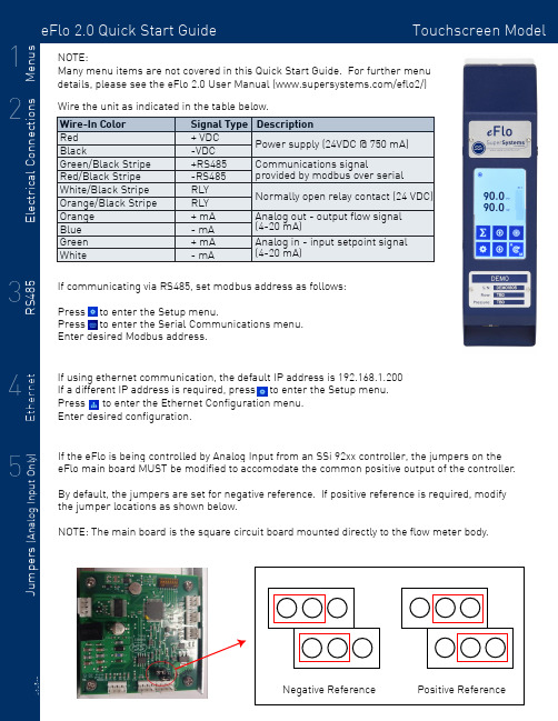
eFlo 2.0 Quick Start Guide Touchscreen Model Signal Type Description + VDC -VDC +RS485-RS485RLY RLY + mA - mA + mA - mA Power supply (24VDC @ 750 mA)Communications signal provided by modbus over serial Normally open relay contact (24 VDC)Analog out - output flow signal (4-20 mA)Analog in - input setpoint signal (4-20 mA)If communicating via RS485, set modbus address as follows:Press to enter the Setup menu. Press to enter the Serial Communications menu.Enter desired Modbus address.Many menu items are not covered in this Quick Start Guide. For further menu details, please see the eFlo 2.0 User Manual (/eflo2/)Positive ReferenceWire the unit as indicated in the table below.Apply gas pressure to the flow meter. Press to enter the Setup menu.Press to enter the Process Variables menu.Hold for two seconds to enter manual mode. Fully close the motor valve by holding the down arrow until the motor drive icon displays .Press to complete the zero tare. Hold to return to auto mode.SSi recommends all flow meters have a zero tare performed for optimal accuracy and control and to equalize the output signal of the differential sensor .If control is unstable or false flow values are indicated when it has been verfied that no gas is passing through the meter, a zero tare may be required.To perform a zero tare:If the meter will be used in Valve mode, a max tare MUST be performed to set the max valve position. To perform a max tare:For additional information, troubleshooting, or other help, see the eFlo 2.0 Quick Reference Guide,the eFlo 2.0 Operations Manual, or contact SSi at 513.772.0060.Apply gas pressure to the flow meter. Press to enter the Setup menu.Press to enter the Process Variables menu.Hold for two seconds to enter manual mode. Hold the Up Arrow until desired max flow is displayed.Press to complete the zero tare. Hold to return to auto mode.Press to enter the Setup menu.Press to enter the Basic Configuration menu.Set altitude to desired level IN FEET.。
T-FBK 2反馈抑制器操作指南
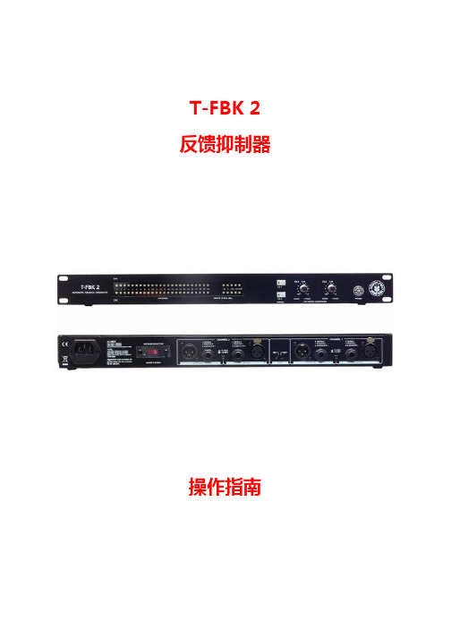
T-FBK 2 反馈抑制器操作指南目 录一、技术参数 (3)二、产品性能 (4)三、快速设定 (5)1、快速设定-定点滤波器 (5)2、快速设定-动态滤波器 (5)四、控制部分 (7)前面板 (7)后面板 (9)五、用户使用 (10)1、音频系统设置 (10)2、设置滤波器状态 (13)3、清除滤波器 (14)4、解锁和锁定 (14)5、滤波器自动释放 (14)一、技术参数型号模拟输入2 x XLR and 2 x 1/4" TRS 平衡/非平衡,RF滤波器抑制输入阻抗 30K 欧姆 平衡 / 15K 欧姆 非平衡 最大输入线路电平 +20.5 dBu模拟输出2 x XLR and 2 x 1/4" TRS 平衡/非平衡,RF滤波器抑制输出阻抗 100 欧姆 平衡 / 50 欧姆 非平衡最大输出电平 +14.5 dBuA/D 转换动态范围 114 dB, A-加权A/D 转换 24 bitD/A 转换动态范围 100 dB, A-加权D/A 转换 24 bit系统性能采样率 48 kHz动态范围 100 dB, A-加权总谐波失真 0.01 %, 1 kHz信噪比 100 dB, A-加权频率响应 20 Hz to 20 kHz, +/- 0.5 dB工作电压 230 VAC 50/60 Hz 115 VAC 50/60 Hz功耗 15 W物理参数尺寸 483 x 195 x 44 mm重量 3.1kg二、产品性能每个通道都有24个可编程的滤波器两个独立处理通道所有滤波器可自由分配在定点及动态模式具有全自动动态滤波器释放功能所有滤波器的Q值可调,适合音乐/演讲等任何场合 每通道有24个滤波器指示灯2个XLR,2个TRS平衡输入输出接口可选择工作电平指示开关(+4dBu/-10 dBu)后面板具有当前设定锁定开关三、快速设定1、快速设定-定点滤波器将T-FBK 2连接到系统中,首先需要设置定点滤波器①、长按每通道旁路按钮4秒钟左右,每通道的24个滤波器的指示灯将开始闪烁②、逐渐加大系统输出音量:T-FBK 2将逐渐搜索到每个反馈点并激活滤波器,相应的指示灯将会发亮③、一般环境下,10-16个定点滤波器已经足够保证系统安全,并不会对音质做任何的修饰和影响④、迅速的按下通道的旁路按钮,则可以退出定点设置模式并且存储已设置好的定点滤波器:所有的滤波器指示灯会亮几秒钟,然后会看到仅有已存储的定点滤波器指示灯保持发亮,其他的则熄灭⑤、此时设备剩余下的未被设定为定点方式的滤波器则进入动态状态,同时设备进入自动搜索状态2、快速设定-动态滤波器①、在现场演出中,偶然发生的反馈一直将会被自动搜索并且清除:当某一个动态滤波器的指示灯发亮,则表明这个动态滤波器已被激活②、如果所有定点和动态滤波器的指示灯都在发亮,则表示所有动态滤波器被使用,T-FBK 2则可以用新拦截的反馈,取代原来最少的使用的动态滤波器,同时相应的指示灯将会闪烁③、您可以在进行实时操作时,根据您的音源情况来调整滤波器Q值:一般情况下,我们建议以音乐为主时调整到1/80th,以演说为主时调整到1/5th④、如果您需要重新设置动态滤波器,长按旁路按钮2秒左右直到仅亮已设置的定点滤波器的指示灯时松手,即可恢复所有动态滤波器⑤、如果您需要重新设置整个抑制器,长按旁路按钮4秒左右直到所有24个滤波器指示灯全部开始闪烁,则表示所有滤波器已全部被清除,并进入定点滤波器设定状态四、控制部分前面板1、24 FILTERS(滤波器指示灯)此产品每通道拥有24个滤波器指示灯,这些指示灯用于提示被激活的滤波器的数量。
E2 控制器通信手册说明书

E2 Controller Communications ManualInstallation,Operation and Maintenance Manual Supplemental Instruction Manual Field Server 6000/7000 MIBE2 Controller Communications ManualPrefaceThese set-up procedures supplement the Installation and Operation Manual that is provided with your network communications device.NoticeThis document contains information protected by copyright. All rights are reserved. The owner of the equipment for which this manual is written may photocopy the contents of this manual for internal use only. No part of this document may be photocopied, reproduced, or translated into another language for use by anyone other than the owner of the equipment for which this manual is written without the prior written consent of STULZ Air Technology Systems, Inc. (STULZ).This document contains confidential and proprietary information of STULZ Air Technology Systems, Inc. Distributing or photocopying this document for external distribution is in direct violation ofU.S. copyright laws and is strictly prohibited without the express written consent of STULZ. Unpublished — rights reserved under the copyright laws of the United States and of other countries. Other brands and tradenames are trademarks of their respective owners. Copyright 2014 by STULZ Air Technology Systems, Inc. Printed in the United States of America.All rights reserved.STULZ Air Technology Systems, Inc.1572 Tilco DriveFrederick, MD 21704, USAhttps:///en/Table of ContentsBACNET MSTP (2)BACNET IP/Ethernet & Modbus TCP (10)MODBUS RTU (15)pCOWeb Clock Configuration (16)C6000 MIB (17)Field Server (20)Flash Memory Life (23)1.RJ11 telephone connection (J10) for display panel2.Connection for pLan (J11)3.Hatch for BMS card4.Power on LED (Yellow)5.Signal LED’s (Red, Yellow, and Green)6.Hatch for expansion I/O module(s)7.Power connector (J1)BACNET MSTP1.Before attempting to communicate with the pConet card, an RS485 adapter and Carelsoftware (BACset) is required.The communication software is a free utility that may be downloaded at , or by using the link below./home?p_p_state=maximized&p_p_mode=view&saveLastPath=0&_58_ struts_action=% 2Flogin%2Flogin&p_p_id=58&p_p_lifecycle=0&_58_redirect=%2FExample: USB – RS485 converter2.Each card has a default address of 77000 (device instance), the card must be initializedto communicate with it.3.Turn the units power off, hold the pushbutton and restore power.The status LED must flash three times for the initialization process, release the push button after the third flash.After power up, use the following starting sequence.▪Two seconds after restarting: quick flash red-green-red green▪Five seconds after restarting: green on steady▪About fifty seconds after restarting: the status LED flashes to indicate quality of communication with pCo▪Quick green – off green: communication with pCo is okay▪Slow red – off red: communication has not been established▪Green-red-green: pCOnet detects error or lack of response from the pCoAfter initialization, use the following start sequence.▪After fifty seconds: slow green-red-green-red, at the end BACnet will be active.▪RS485 LED indicates status of communication with the network by displaying green with occasional red flashes when communication is active.4. A shortcut will be saved to your desktop, click on the BACset icon to open the utility.5.Select MS/TP, if a router is being utilized select the correct configuration, if not select norouter.6.If you receive a COM error confirm your port/RS485 settings; 19200 baud rate andassigned port.7.If your computer port settings are correct, and the card remains inaccessible, start BACsetin IP mode..Note: this area is blank when you are not communicating with the card.8. When the BACset screen opens locate the BACdoor icon in your taskbar, select the icon and configure menu in BACdoor.9.Set the MS/TP parameters, the Com Port must match your computer settings, the TS(MS/TP Node) must always be higher than the node you are attempting to communicate with on the network.10.Try starting out with a default setting of 15 or higher to allow access without changing thisparameter frequently.11.Once the parameters have been set, select OK.12.Close BACset and reopen the utility to discover card.NOTE: This error may occur with Window 7 OS, locate the file online and download to your computer.13.If all settings are correct the following screen would appear after opening BACset, clickread to establish communication with the card.14.If the card device instance has been changed, the new device instance shall be displayed viaBACdoor when discovered.15.Change the device instance for the desired network member your computer is connected to,and then click the read icon.The read/write status should display 100% when complete.16.When communication has been established with the card, settings may be changed.17.The MS/TP station address, max master and baud rate may be changed. Do this first.18.After entering the requested data in the fields click write to save the settings.19.Enable the write option to change the device instance; the shaded box will turn “white”allowing the change from 77000 to the desired instance number.20.Once the desired device instance has been entered select write>reboot, the card will beaccessible within 2 minutes following the reboot.NOTE: The BACdoor baud rate must match the card setting, open BACdoor and change the baud rate, close BACset and reopen to connect with the pCOnet card.* Must reboot have to be performed after “all” writes to the card!21.After configuration of the card commissioning can be performed, all variables (analog &binary) are accessible. You may read or write to variables when testing, reference the STULZ BMS table for data type.BACNET IP/Ethernet & Modbus TCPNOTE: One card is utilized for these protocols.1.Disable your wireless connection on your lap top computer.2.Set IP Address and subnet mask of PC to 172.16.0.2 / 255.255.0.0 (pCOWeb manual3.1.1).3.Connect the Ethernet cable from the PC to the pCOweb card (manual 3.1.2).4.Reboot the IP card: push the reset button on the IP card and observe LED, continueholding until the LED flashes three times then release. (manual 3.1.2).5.Perform a ping to verify communicationa.start>run>cmd>okb.type Ping 172.16.0.1 (DOS screen)c.close window if ping is successful6.Open Internet Explorer on PC and type in address field 172.16.0.1 (manual 3.1.4).7.The pCOWeb page will appear.8.Click go to administrator area.9.Enter username (admin) and password (fadmin).10.Select OK (manual 8.2.1).After the IP address has been entered in internet explorers address field, the pCOWeb page will display if the initialization process, and computer settings are correct,11.To change the card settings select configuration and then network to change the IP address,netmask and desired gateway address.12.The IP address, NetMask & Gateway address must be entered in the fields as shown below. Areboot must be performed to save the writes, do not power off the unit during the reboot process.13.After the reboot process has been completed change the computers IP & NetMask to reflect thatof the card, the computer IP address must be higher than the communication card addressotherwise communication will not be possible.14.Modscan32 may be utilized to confirm communication with a pCOWed card when Modbus TCPhas been selected as the communication protocol.NOTE: Integer variables in the E2 BMS Table start with address 5002 (5001 + offset of 1).MODBUS RTUe any Modbus diagnostic utility and a RS485 converter to establish a connection withthe Modbus card.2.The computer port settings and converter must be set for 19200 baud rate, set thediagnostic utility connection settings likewise.3.Confirm communication using the E2 BMS Table, demo versions of Modscan may beobtained from WinTECH Software Design, free of charge./html/demos.htmNOTE: Connect the RS485 converter to the communication card +/- terminals.pCOWeb Clock Configuration1.Configure the pCOweb card integers (123‐127)* to maintain date and time after power cycles, changethe variables as reflected below and click submit to save card settings.*Not used with STULZ DESICAiR E2series controllers.E2 BMS Table Integer VariablesC6000 MIB1.To use MODBUS poll or MODSCAN configure your port for RS485; connect yourRS485 converter to MIB terminals 13 and 14.Converter Terminal A – MIB terminal 14Converter Terminal B – MIB terminal 132.Contact Stulz Product Support for the C7000 service program for MIB setup, hyperterminal may also be used to configure the MIB.3.Set the protocol (Modbus), baud rate and port settings to be utilized with the customersBMS.4.Modscan may be used to simulate a BMS interface to verify communication with theCRAC units./html/demos.htm5.The MIB C6000 only supports the following Modbus registers, reference Stulzdocumentation “before” system integration!NOTE: MIB communication confirmed via MODSCAN32.Field Server1.Download the field server utility:/techsupport/utility/downloads.php2.Set the computer IP address and NetMask, the wireless connection should be off duringtesting.3.Open the field server remote user interface for bridge access.NOTE: The default gateway address must be set as assigned per the network.4.Wireshark captures may be obtained to determine communication conflicts, in the filtersection enter “port not 1024” to capture all Ethernet traffic.Flash Memory LifeNo matter how recent the hardware is in a controller, any flash memory has a limited life cycle for the number of write cycles. A typical number is 1 million cycles (1,000,000) which if someone is writing to every 10 seconds, can be reached rather quickly. The unit will last 115 days.60 seconds per minute, 60 minutes per hour = 3600 seconds3600 10 360 8640 115.7 0.33600 20 180 4320 231.5 0.63600 30 120 2880 347.2 1.03600 60 60 1440 694.4 1.93600 120 30 720 1388.9 3.83600 300 12 288 3472.2 9.53600 600 6 144 6944.4 19.0North American HeadquartersSTULZ Air Technology Systems, Inc. 1572 Tilco Drive | Frederick, MD 21704301.620.2033|Fax:301.662.5487|****************** Technical Support: 888.529.1266。
Fishman ToneDeq AFX2用户手册说明书
USER GUIDEImportant Safety InformationTo ensure your personal safety and the safety of others, operate this apparatus only after completely reading this instruction manual and heeding the warnings listed below.This equipment has been tested and found to comply with the limits for a Class B digital device, pursuant to Part 15 of the FCC Rules. These limits are designed to provide reasonable protection against harmful interference in a residential installation. This equipment generates, uses, and can radiate radio frequency energy and, if not installed and used in accordance with the instructions, may cause harmful interference to radio communications. However, there is no guarantee that interference will not occur in a particular installation. If this equipment does cause harmful interference to radio or television reception, which can be determined by turning the equipment off and on, the user is encouraged to try to correct the interference by one or more of the following measures:– Reorient or relocate the receiving antenna.– Increase the separation between the equipment and receiver.– Connect the equipment into an outlet on a circuit different from that to which the receiver is connected.– Consult the dealer or an experienced radio/TV technician for help.NOTE: Fishman Transducers, Inc. is not responsible for unauthorized equipment modifications that could violate FCC rules, and/ or void product safety certifications.EU Declaration of Conformity CE: Hereby, Fishman declares that this ToneDEQ is in compliance with the essential requirements and other relevant provisions of Directive 2004/108/EC.Copyright © 2016 FISHMAN TRANSDUCERS, INC.All rights reserved. No part of this document may be reproduced in any form without the written permission of FISHMAN TRANSDUCERS, INC.WelcomeThank you for making Fishman a part of your acoustic experience. We are proud to offer you the finest acoustic amplification products available; high-quality professional-grade tools to empower you to sound your very best. We are confident TONEDEQ | AFX will both enhance and inspire your music making.Quick StartPower • Install a fresh 9V battery (not included) or connect a Fishman 910-R power adapter.Set the controls •Volume at minimum and all other controls as shown below. Plug in • Use standard ¼-inch and XLR shielded instrument cables.Set input trim • Play hard and adjust the input trim (on the right side) so the level LED lights green and occasionally flashes red.T urn up • Raise the volume and adjust the low, mid and high controls.Select effects • Audition effects using their select knobs and foot switches. Adjust each effect’s intensity using its individual level control.Left Side Panel9VDCPower may be supplied by either a 9V battery (battery compartment underneath the pedal) or the Fishman 910-R power adapter.XLR D.I. OutputConnect a standard microphone cable here to feed recording equipment or a sound reinforcement mixing console. When the 1/4” output is also connected, this D.I. output’s ground is automatically lifted to prevent any unwanted ground loops. This D.I. provides a fixed-level output, unaffected by the volume control.D.I. Output Pre/PostChoose between a true D.I. (pre EQ) or an effected XLR output (post EQ).• Post is useful in live venues (especially if you are mixing from onstage) where you want your “dialed-in” sound to come through the PA.• Set this switch to the Pre position when you want a “flat” DI signal going to the board and you wish to leave it to the sound-person orrecording engineer to dial up the instrument tone from their console. Amp OutputUse a standard ¼-inch instrument cable to connect the amp output to your amplifier, mixer or effects devices. You can also connect the amp output to an unbalanced input on a recording system.Right Side PanelInputPlug in your instrument here with a standard ¼-inch instrument cable. If you have a passive undersaddle pickup (no battery onboard), always plug into this preamp pedal first, even if you use a pedal tuner.Insert a plug into the input jack, and the TONEDEQ | AFX powers up. To conserve the battery, remove the plug from the input when not in use.Input T rimRaise or lower the input trim to optimize the input level for your pickup. Play hard and adjust input trim so the level LED lights green and occasionally flashes red. Some pickup systems may not cause the light to flash red at all and other onboard preamps may require you to turn their output down to achieve an optimum level.Boost LevelThe amp output and D.I. output level can be boosted using the boost foot switch. The boost level controls the amount of increased output level from 3dB to 9dB.Front PanelVolumeThe volume control affects the 1/4 inch output level only.For the cleanest signal, set the volume as high as possiblewithout clipping the next device in the signal chain. If youhear distortion and the level light is not flashing red,reduce the volume. For setting proper levels, refer toinput trim on page 5.CompressorThe compressor uses a sophisticated leveling circuit to automatically reduce the volume of loud sounds determined by your playing level and the setting of the compressor control.As you turn this knob clockwise, your overall playingdynamics become increasingly limited, making softernotes louder and controlling loud spikes in yourplaying. This can be helpful in performances whereyou desire a more even level to your playing. At itsmaximum setting, there may be some overallincrease in the output level.The active LED will light green to indicate that thecompressor is beginning to affect your dynamics. If the signal level continuesto increase to the point where 6dB of compression has occurred, the LED will change to amber.Battery ReplacementThe batt indicator will light steadily when it is time to change the battery. Open the battery door underneath the pedal and install a fresh 9V alkaline or lithium battery. When the batt LED comes on you have approximately one hour of remaining battery life. Approximate battery life is 12 hours using common alkaline battery and 18 hours with a lithium battery.Tone ControlsLow• Boost here to add depth and weight to the sound of the instrument.Mid • Turn all the way left for a smooth “scooped out” tone at high volumes. Raise the control to the right of center to add midrange “bite” to the sound. High • Boost to cut through the mix. Cut to mellow and subdue the sound.Low Cut • Adjust this control to affect the lowest frequencies that can cause “rumble” or thumping sounds while you play.PhaseThe phase switch flips the polarity of your instrument signal frompositive to negative, changing its relationship to the soundcoming from the amplifier. One phase setting usually providesbetter resistance to feedback than the other and will varydepending on the instrument and playing environment.Another approach to determining optimal phase is the selection which sounds or feels most natural when playing. In certain playing environments the phase switch may not have an audible impact.The phase switch also affects the signal polarity to the balanced XLR D.I. and 1/4 inch outputs, synchronizing the amp output with other sound systems in use.BoostThe boost foot switch increases the pedal’s overall outputlevel at the amp and D.I. output from 3dB to 9dB. Whenactivated, the LED above the foot switch will light steadily.The amount of level increase is determined by the boost levelcontrol on the pedal’s right side panel.TONEDEQ | AFX offers two independent effects processors that run in parallel with the analog preamp, compressor and EQ circuits to reduce the effect of coloration on your instrument’s sound.Reverb & Delay EffectsTime • Sets the overal “length” of the reverb or delayeffect. For reverb effects, increasing this control will makethe reverb “tail” more obvious. For delay effects, increas-ing this control will add space between each repeat.Level • The level control mixes the effect in parallel,adding as much or as little effect into your direct sound.Effects:• Reverb 1• Reverb 2• Delay 1• Delay 2Block DiagramChorus EffectsRate • Sets the speed (rate) or intensity of the selected effect.Level • The level control mixes the effect in parallel, adding as much or as little effect into your direct sound. Effects:• Chorus 1• Chorus 2• Flanger• TremoloTechnical SpecificationsInput impedance: 10M OhmInput trim gain range: -6dB to +14dBNominal Output impedance: 1k Ohm, Amp Output600 Ohm, D.I. Output Maximum Output level: +8dBV (onset of clipping) Baseline noise: -91dBV (A-weighted)Dynamic range: 97dB (A-weighted)Typical in-use current consumption: 37mA (62mA max.)Typical 9V battery life: 12 hours using alkaline battery18 hours using lithium battery)9V adapter: Fishman 910-Ror suitable filtered and regulated,200mA type, tip = negativeTone Controls:Low cut: 40Hz, 80Hz, 160HzLow control: ±14dB @ 100HzMid control: ±12dB @ 700Hz, Q=1High control: ±*********** Compressor:Threshold: VariableRatio: 2.3:1Phase switch: Left position = non-invertingBoost: Variable: +3dB to +9dBDimensions: 5.6” D x 9.5” W x 2.2” H142mm D x 240.8mm W x 55mm H Weight: 2.2lbs (1.0kg)We reserve the right to change any of the the specifications and information in this manual without notice.11Fishman and Fishman Transducers are trademarks or tradenames of FISHMAN TRANSDUCERS, Inc. 513-300-199 Rev 3 3/16。
欧图II反馈抑制器用户手册
User's ManualVersion 1.2 April 18, 2008EnglishDIGITAL PROCESSORAutomatic Feedback KillerTERMINATOR IIc All rights reserved to ALTO. All features and content might be changed without prior notice. Any photocopy, translation, or reproduction of part of thismanual without written permission is forbidden. Copyright 2007 Seikaku GroupSEIKAKU TECHNICAL GROUP LIMITEDNO. 1, Lane 17, Sec. 2, Han Shi West Road, Taichung 40151, Taiwan T el: 886-4-22313737email: alto@ Fax: 886-4-22346757NF02949-1.2IMPORT ANT SAFETY INSTRUCTIONWARNINGTo reduce the risk of electric shockand fire, do not expose this equipmentto moisture or rain.1.2.3.4.5.6.7.8.9.10.Dispose of this product shouldnot be placed in municipal wasteand should be separate collection.11.12.Move this Equipment only with a cart,specified by themanufacturer, orsold with theEquipment. Whena cart is used, usecaution whenmoving the cart /equipmentcombination toavoid possiblePermanent hearing loss may be caused byexposure to \ extremely high noise levels.The US. Government's Occupational Safetyand Health Administration (OSHA) hasspecified the permissible exposure to noiselevel.These are shown in the following chart:According to OSHA, an exposure to high SPL inexcess of these limits may result in the loss ofheat. To avoid the potential damage of heat, it isrecommended that Personnel exposed toequipment capable of generating high SPL usehearing protection while such equipment isunder operation.may be sufficient to constitute the risk of electricProtective Ground T erminalAC mains (Alternating Current)Hazardous Live T erminalON: Denotes the product is turned on.OFF: Denotes the product is turned off.The apparatus shall be connected to a mainssocket outlet with a protective earthingconnection.The mains plug or an appliance coupler is usedas the disconnect device, the disconnect deviceshall remain readily operable.CAUTIONDescribes precautions that should be observed toprevent damage to the product.Keep this Manual in a safe place.Be aware of all warnings reportedwith this symbol.moisture.Clean it only with dry cloth. Do not usesolvent or other chemicals.Do not damp or cover any cooling opening.Install the equipment only in accordance withthe Manufacturer's instructions.Power Cords are designed for your safety. Donot remove Ground connections! If the plugdoes not fit your AC outlet, seek advice froma qualified electrician. Protect the powercord and plug from any physical stress toavoid risk of electric shock. Do not placeheavy objects on the power cord. This couldcause electric shock or fire.Unplug this equipment when unused for longperiods of time or during a storm.Refer all service to qualified service personnelonly. Do not perform any servicing other thanthose instructions contained within theUser's Manual.To preven t fire and damage to the product,use only the recommended fuse type asindicated in this manual. Do not short-circuitthe fuse holder. Before replacing the fuse,make sure that the product is OFF andHOURS X DAY EXAMPLE864321,510,50,25 or lessSPL90929597100102105110115Small gigtrainSubway trainHigh level desktop monitorsClassic music concertRock concert1. TERMINATOR II QUICK START - SET UP MODE1.1 After connecting TERMINATOR II to the mixer channels or subgroups follow these points:1.2 Press and hold the BYPASS button (for more than 4 seconds) related to the channel you want to set up (CHANNEL 1 or CHANNEL 2): all 24 filter leds will start flashing1.3 Start generating intentional feedbacks increasing slowly the GAIN/VOLUME on the mixer: TERMINATOR II will activate gradually the filters and the correspondent leds will light1.4 Usually 10 to 16 filters are enough to guarantee a safe set up without modifying the audio timbre1.5 Remember you can use up to 2 independent channels connected to TERMINATOR II1.6 T o exit SET UP MODE and to STORE the fixed filter press quickly the related channel BYPASS button: all filter leds turn on for a few seconds, then only the stored ones keep on lighting1.7 Now TERMINATOR II is set on LIVE MODE And in such cases, all the expenses will be charged to the buyer .3.5 In no event shall be liable for any incidental or consequential damages. L TO Some states do not allow the exclusion or limitation of incidental orconsequential damages, so the above exclusion or limitation may not apply to you.3.6 This warranty gives you the specific rights, and these rights are compatible with the state laws, you may also have other statutory rights that may vary from state to state.7. WARRANTYQUICK START2.1 During the performance the accidental LIVE feedbacks are automatically detected and killed: a new led will light to indicate the activation of a new LIVE filter2.2 If occasionally all 24 filters are activated (all filter leds on) and new LIVEfeedback occurs, TERMINATOR II is able to kill the new feedback substituting the oldest less-used filter: the correspondent led will start flashing2.3 Y ou can operate in real time on the LIVE MODE VARIA TIONS to adjust the filter Q according to your audio source: generally for Music we suggest to turn the knob towards 1/80th, for Speech towards 1/5th)2.4 If you need to RESET the LIVE filters (keeping the FIXED ones previously stored during the SET UP MODE) press and hold the BYPASS button for about 2 seconds till only the FIXED filter leds keep on lighting2.5 If you need to RESET completely TERMINATOR II and start a new SET UP , press and hold the BYPASS button for more than 4 seconds till all 24 filter leds will start flashing2. TERMINATOR II QUICK START - LIVE MODEAbnormal service or repairing by anyone other than the qualified personnel or technician.and contact telephone number.2.3 A brief description of the defect will be appreciated.2.4 Please prepay all the costs involved in the return shipping, handling and insurance.3. TERMS AND CONDITIONS3.1 warrants that this product will be free from any defects in materials L TO and/or workmanship for a period of 1 year from the purchase date if you have completed the Warranty Registration Card in time.3.2 The warranty service is only available to the original consumer, who purchased this product directly from the retail dealer, and it can not be transferred. 3.3 During the warranty service, may repair or replace this product at its L TO own option at no charge to you for parts or for labor in accordance with the right side of this limited warranty.3.4 This warranty does not apply to the damages to this product that occurred as the following conditions:Instead of operating in accordance with the user's manual thoroughly, any abuse or misuse of this product. Normal tear and wear.The product has been altered or modified in any way.Damage which may have been caused either directly or indirectly by another product / force / etc.the returned machine, and give detail information about your return address 2.2 Please provide a copy of your sales receipt or other proof of purchase with unit from any other extra damage.product is well packed in its original shipping carton, and it can protect your 2.1 In case of return for any warranty service, please make sure that the2. RETURN NOTICEyour warranty service. 1. WARRANTY REGISTRATION CARDT o obtain Warranty Service, the buyer should first fill out and return the enclosed Warranty Registration Card within 10 days of the Purchase Date.All the information presented in this Warranty Registration Card gives the manufacturer a better understanding of the sales status, so as to provide a more effective and efficient after-sales warranty service. Please fill out all the information carefully and genuinely, miswriting or absence of this card will voidIN THIS MANUAL:1. INTRODUCTION........................................................................12. FEATURES...............................................................................13. CONTROL ELEMENTS..............................................................24. USER SETUP ...........................................................................45. INSTALLA TION & CONNECTION.................................................76. TECHNICAL SPECIFICATIONS..................................................10 7. WARRANTY (11)2. FEATURESThank you for your purchasing of the L TO TERMINATOR II. The TERMINA TOR II is a Dual Channel Digital Processor . It is designed to provide state of the art Feedback elimination processing, for fixed installation or live event, while maintaining a simple and intuitive control interface.The TERMINATOR II provides up to 24 filters per channel (CH1 & CH2), offers independent selectable modes, live filters lift, process bypasses, continuously variable types of filtration, with widths between and Octave of which are all available on a intuitive user interface front panel.th th 1/801/5 Enjoy your TERMINATOR II and make sure to read this Manual carefully before operation!24 Programmable Filters per Channel Dual Independent Channel Processing Live and Fixed Filter Modes Automatic Live Filter Release Selectable Application of proprietary Filter Variations (Music/Speech)L TO 2Input Channel Metering 24 LED Filter Metering per Channel2 XLR and 2 x TRS Electronically Balanced Inputs and Outputs Selectable Operating Level Switches (+4 dBu / -10 dBv) Rear Panel Lockout Switch1. INTRODUCTION2 x female XLR and 2 x 1/4" TRS Electronically Balanced / Unbalanced, RF filter suppressor Max Input line level 2 x male XLR and 2 x 1/4" TRS Electronically Balanced / Unbalanced, RF filter suppressor Max Output level Dynamic Range D/A Performance D/A ConversionSample Rate THD+N % Power Consumption Power Requirement 6. TECHNICAL SPECIFICA TIONAnalog InputsInput impedance 30k ohm Balanced / 15k ohm Unbalanced +20.5 dBuAnalog OutputsOutput impedance 100 Ohm Balanced / 50 Ohm Unbalanced +14.5 dBuA/D Performance 114 dB, A-weighted A/D Conversion 24 bitDynamic Range 100 dB, A-weighted 24 bitSystem Performance 48 kHzDynamic Range 100 dB, A-weighted 0.01 %, 1 kHzFrequency Response20 Hz to 20 kHz, +/- 0.5 dB Inter channel Crosstalk Crosstalk input to output Operating Voltage230 VAC 50/60 Hz 115 V AC 50/60 Hz 15 W100 dB, A-weighted 100 dB, A-weightedPhysicalS/N Ratio100 dB, A-weightedDimension Net Weight483 x 195 x 44 mm 3.1kgFront Panel:The TERMINATOR II offers 24 notch filters (RED LED) for each channel, which are used to indicate the number of active notch filter . The LEDs that always blink for each channel is the last Live inserted notch filter .a -This button is used to bypass the notch filters in the s ignal path by pressing quickly (about 1 second).) is used to reset the LIVE filters (CLEAR 2 Sec.).c -BYPASS button (more than 4 Sec.) is used to reset the fixed filters and enter the SETUP Mode (SETUP 4 Sec.).For more information of filter reset, please see the Clearing Filters in the USER SETUP section.b -Pressing and holding the BYP ASS button (about 2 Sec Pressing and holding the3. CONTROL ELEMENTS 3. CONTROL ELEMENTS2 BypassThis knob is used in LIVE MODE to select the application of AL TO proprietary notch filter , independently on CH1 & CH2.Each selected mode controls the width ( to of the notch filter used to remove the feedback, the velocity of the filter activation and the sensibility in the feedback analysis.th th1/801/5) 3 LIVE Mode VariationsThese four LEDs indicate input level of the TERMINATOR II with a range from -10 dBu to +18 dBu.NOTE: For maximum performance and proper operation, the average input signal should consistently light up at the 0 dBu LED and the +10 dBu LED lighting occasionally.4 Input Level Bar GraphThis LED indicates that there is signal clipping at the Inputs. If necessary, verify the correct position of input selector -10dBv /+4dBu, or setting the level of the chain with a external pink noise signal. 5 Clip LED6 Power SwitchIt switches your TERMINATOR II On/Off .ON LINE with the Outputs of the Mixer1- Connect the Outputs L -R from the mixer to the inputs CH 1 & CH 2 ofTERMINATOR II with the XLR or TRS (tip-ring-sleeve) stereo jack.2- Connect the Outputs CH1 & CH2 of TERMINATOR II at the Inputs of power amplifiers.3- Set the sensitivity at +4 dBu on the TERMINATOR II and adjust the L -R fader control on the MIXER for having a necessary level on TERMINATOR II.For maximum performance and proper operation, the average input signal should consistently light up at the 0 dBu LED and the +10 dBu LED lighting occasionally.3. CONTROL ELEMENTS 5. INSTALLA TION AND CONNECTION3. CONTROL ELEMENTS 3. CONTROL ELEMENTSRear Panel:Two types of input connectors are provided for input connections: 2 x female locking XLR type connectors, and 2 x 1/4" TRS jack connectors (tip-ring-sleeve). The maximum input level that the processor can accept is +20 dBu (ref.: 0.775Vrms).This button allows you to select between either +4 dBu or -10 dBv nominal operating level.This switch locks/unlocks all access to the front panel of the TERMINATOR II.7 AC Inlet and Fuse holder9 Input/Output Connectors10 Operating Level Switch11 Lock Switch8 Voltage SelectorThis switch has two choices for voltage, 100-120 VAC or 220-240 V AC.Standard IEC receptacle. Connect your TERMINATOR II to the AC Inlet with the supplied AC power cord. Before powering up your TERMI N ATOR II for the first time, make certain the stated power requirement of the unit matches the voltage supplied by the AC socket.If the fuse blows, replaced with a fuse of the correct type only.Insert on the SUB GROUP/MAIN L-R of the Mixer1- Connect the TRS (tip-ring-sleeve) stereo jack into the Mixer SUB GROUP/ MAIN L-R, Insert sock et.2- Connect the Send stereo jack (unbalanced) to the CH1 Input of TERMINATOR II and the CH1 Output of TERMINATOR II with a Retu rn ste reo jack (unbalanced). 3- Set the sensitivity at -10 dBu on the TERMINATOR II and adjust the SUB GROUP/ MAIN L-R, fader control on the MIXER for having a necessary level on TERMINATOR II.For maximum performance and proper operation, the average input signal should consistently light up at the 0 dBu LED and the +10 dBu LED lighting occasionally.3. CONTROL ELEMENTS5. INSTALLA TION AND CONNECTION4. USER SETUPThere are three basic ways you can use the TERMINATOR II combine with your audio system. It can be:1. Connected to a MIC channel of a MIXER, into the "Insert" jack (send/return).2. Connected to the SUBGROUP/MAIN OUTPUTS (L/R) of a MIXER into the "Insert" jack (send/return).3. Connected "ON LINE" between mixer and PA system. From output of the Mixer to i n put of TERM INA TOR II and from Output of TERMINATOR II to P A input (Stereo Amplifier).The connection of TERMINATOR II to Insert points, is probably the bestselection, the levels present in most mixers are pre-fader , (normally 10 dBu) and flow direct to TERMINA TOR II. In this way any fader level variations do not modified the setup of TERMINATOR II.For the best performance and proper operation, the average input signal should consistently light up at the 0 dBu LED and the +10 dBu LED lighting occasionally.The above setup is used when insert points are not available, set the TERMINATOR II at +4 dBu, this value is correct when you connect the outputs of any mixer directly to the input of TERMINATOR II.For the best performance and proper operation, the average input signal should constantly light around 0 dBu LED and the +10 dBu LED should light only occasionally. 2 SETUP & LIVE ModeThe TERMINATOR II offers a total number of 24 notch filters for each channel (CH 1/CH 2) and two main operation modes:a -SETUP mode, with the fixed filters.b -LIVE mode, with the free filters not used in SETUP mode.The SETUP mode is used to detect and remove feedback problems in the audio system due to the microphone placement, different environments shapes, etc. Once these filters are set, they can't be removed unless you reset then again.The LIVE mode is used to detect and remove feedback in "real-time", during the musical events.1. Using SETUP Mode (SOUND CHECK)Fixed filters are set before a performance in a process called ringing out a system, this is done after all other setting system has been done.a -First, bring down the main mix, turn off all music sources and open the MIC (if you use Vocalist) or the different MIC (if you use a Sub-Group).The filters, not used in SETUP mode, automatically work in LIVE mode, the last filter included blink.free 1 Setting Audio System3. CONTROL ELEMENTS 5. INSTALLATION AND CONNECTIONInsert on the MIC channel1- Connect the TRS (tip-ring-sleeve) stereo jack into the mixer MIC channel, Insert socket.2- Connect the Send stereo jack (unb alan ced) to the CH1 Input of TERMINATOR II and the CH1 Output of TERMINATOR II wit h a Return stereo jack (un bala nced ).3- Set the sensitivity at -10 dBu on the TERMINA TOR II and adjust the MIC Gain control on the MIXER for having a necessary level on TERMINATOR II. 4- Repeat the same step connections for the CH2 of TERMINATOR II if you like to use.For maximum performance and proper operation, the average input signal should consistently light up at the 0 dBu LED and the +10 dBu LED lighting occasionally.Hz+3+2+1 0-1-2-3-4-5-6-7-8-9d B u d B ud -Set the level of each CHANNEL with PFL and slowly turn u p the Main Mix er Volume, raising the gain of the system, until feedback occurs.e -The TERMINATOR II will detect and remove feedback by placing notch filters on the proper frequencies. Continue to slowly raise the gain until allfeedbacks have been eliminated, then exit from SETUP Mode by pressing and releasing the BYPASS button quickly.All LED turn ON for few seconds, indicating fixed filters are STORED and automatically LIVE Mode is selected, the remaining filters are available in LIVE MODE.If all 24 filters have been used in SETUP Mode, the SETUP Mode is left automatically and no more filters are available in LIVE Mode.2. Using LIVE Mode (REAL TIME)The TERMINATOR II operates normally in LIVE Mode (24 notch filters minus the fixed used filters ). Live Mode filters are set on the feedback frequency as soon as a new feedback is detected, according to the knob position of the selected LIVE Mode Variations (from MUSIC to SPEECH).If all LIVE filters are used and a new feedback occurs, the oldest LIVE filter is cleared and reallocate to the new feedback frequency (the correspondent led will light).The TERMINATOR II will continue to search feedback frequency through the LIVE notch filters.4. USER SETUPc -All the 24 LEDs and the BYPASS LED will start flashing, indicating SETUP mode is selected for CH1 or CH2 or together .MUSIC High Q mode, (use notch filters at Octave), continuously variable until SPEECH Low Q mode, (use notch filters at Octave).th 1/80th 1/5ALTO Notch Filter Q Diagramb -Place the TERMINATOR II in SETUP Mode by pressing and holding the BYP ASS button for more than 4 seconds.3 CLEARING FILTERST o reset the LIVE filters, press and hold the BYPASS button on the selectedchannel (for about 2sec till the live filter leds will switch off). The currently active filters will be cleared and the assigned LED will turn off.If you wish to "reset" all the filters, continue to hold the BYP ASS button (more than 4 seconds) until all filter LEDs are "blinking", indicating that you have entered the SETUP Mode and that all filters FIXED and LIVE have been cleared. 4 LOCK ON/OFFWhen you finished setting the TERMINATOR II, you can save your setup, switch ON the LOCK selectors in the rear panel.After this it will be impossible to operate on front panel. 4. USER SETUP5 AUTOMATIC FILTER RELEASEThe AL TO TERMINATOR II provides the user with 24 notch filters, for each channel, they are enough for normal performances. If severalnumbers of filters are required, (more than 16), we strongly recommend to operate a new setup of the sound system.Anyway, even if the TERMINA TOR II uses very narrow notch filters, accordingly with the selected application type, unused notch filters must be avoided, to always guarantee the best audio performance.The TERMINATOR II constantly monitors the status of the LIVE filters and automatically removes the ones that are no longer necessary.。
ELMO VP Receiver VPR-2 用户手册说明书
NOTICE:- Do not use this product outside your Country.- Depending on the specification of the HDMI device, this product may not work properly or there may be some effect on performance.- Compatibilities with supporting models have been confirmed in our environment. - We do not guarantee operation in all environments.- Depending on the devices to be used with this product, CEC function may not be used.- Because the wireless connection takes a time in low temperature environments, please use after switching it on and waiting for a while.- If you use the wireless system close to more than 5 pairs, it takes a little long time to connect by wireless at interference when power is on.- The product design and the specification are subject to change without prior notice. -and are trademark of ELMO Co., Ltd.- All other company/products names described in this manual are trademarks or registered trademarks of respective companies.Contact your dealer if any of the following items are not included in the package. Caution・The Supplied AC attachment is for your country.・When using the product, connect the AC attachment to the AC adapter.Assembling/ disassembling procedure for the AC adapterAssemble or disassemble the AC adapter and the AC attachment by taking the following procedure.Make sure to unplug the cable from the mains power before starting the assembling/ disassembling work..■ AssemblingSlide the AC attachment along the groove of the AC adapter until you hear a “click”.■ DisassemblingPress the centre of the AC attachment and slide it along the groove to remove. Caution *1 Use an appropriate AC attachment for your region.Part Names1. Micro USB power port : AC adapter terminal.2. Menu/Select button : To display or select menu.3. Up button : To scroll up menu items.4. Down button : To scroll down menu items.5. HDMI port : HDMI output terminal.6. Link light : LED to indicate the connection status with the visual transmitter.7. Power light : LED to indicate the power supply condition.8. Remote control sensor . Caution・Please remove the protection sheet of the VP receiver before you use.・The micro USB terminal of the VP receiver is for power supply only and other USB devices cannot beconnected. Use the supplied AC adapter to supply power to the VP receiver. Do not use the bus powered USB to supply power to the VP receiver. The power consumption of the VP receiver is higher than the standard of the USB bus power.・Use the visual transmitter that supports WHDI standard. ・HDMI output of this product complies with HDMI standard.・Because the wireless connection takes a time in the low temperature environments, please use after switching it on and waiting for a while.・When installing this unit please ensure there are no obstacles between the remote control and infrared receiver .Remote Control①Power button : Turn the power ON/OFF(Standby mode) ②OK button : Choose the OSD item ③Up button : Move the cursor up ④Down button : Move the cursor down ⑤Left button : Move the cursor left ⑥Right button : Move the cursor right ⑦Cancel button : Go back in the menu ⑧Menu button : Show the menu on screen ⑨Input button : Select registered video source ⑩Info button : Display the current link information⑪Part of the infrared signal transmission: infrared transmission⑫Battery container : install batteries. (TYPE AAA ×2)Caution・On the back of the remote control lift and pull the battery lid in the direction shown. Remove the lid and insert the two AAA batteries.・If this product is not going to be used for a long time, take the batteries out of the remote control. ・Do not use rechargeable batteries (e.g., Ni-Cd (NiCad batteries)). ・Do not use new and old batteries or batteries of different types together. ・Do not try to recharge or short-circuit the batteries.・When disposing of used batteries, follow the instructions of your local government. ・Insert from one side and pay particular attention to the polarity (+/-directions). ・Be sure to use AAA batteries.・If any liquid from a battery leaks onto your skin or clothes flush the area with clean water immediately. If it gets into your eye, flush immediately with clean water and contact a doctor.・The receivable range may be reduced when the main unit is placed in direct sunlight, near an inverter fluorescent light or in any other unfavourable conditions. Depending on the light source conditions, the sensor may fail to receive any infrared light. In such cases, relocate the main unit or shield the light source.CautionChildren may ingest small batteries. Always keep batteries safe and out of reach.If a battery is swallowed, consult a doctor immediately as this could result in asphyxiation or be an obstacle to digestion, etc.Connecting the VP ReceiverCaution *1 The AC adapter is different according to the destination. *2 Change the input mode of the image output device to HDMI. *3 Use a commercially available HDMI cable (Type A).Turning the power ON/OFFPress the power button on the remote control to turn the power on. To turn the power off, press the power button on the remote control once (standby mode).Configuring the wireless settingsConfigure the wireless settings before using the VP receiver.Before setting the wireless communication, please connect the VP receiver and standard HDMI display ,then turn on the VP receiver and the document camera (MO-1w) manufactured by ELMO.To display the menu screen, push the Menu/Select button on the main unit or the menu button on the remote control, then select "Setup" and push the Menu/Select button on the main unit or the OK button on the remote control. You can add/remove or modify the name of the visual transmitter from the menu.●Add ELMO's document camera (MO-1w) (pairing) 1. Set VP receiver in the add (pairing) mode.Move the cursor to "Setup" with the Up or Down buttons and push the Menu/Select button on the main unit or the OK button on the remote control.Move the cursor to "Add new Video Source" and push the Menu/Selectbutton on the main unit or the OK button on the remote control to enter receive mode.2. Press and hold the pairing button (Located on the side of the MO-1w) on the document camera until appearing "Adding ○ ○ ○(the name of the video transmitter)" appears on the screen.※ About 5 seconds. It may vary depending on the situation.CautionPlease read this instruction manual carefully before using this product and keep it for future reference.INSTRUCTION MANUALInstruction ManualVP Receiver3 4 5 6 7■Link light (Blue) ・Lit : Already matchingwith the visual transmitter.・Blink : Searching for WHDI input signal■Power light (White) ・Lit : Power is ON. ・Off : Power is OFF. ・Blink : Standby modeAC adapter with attachments AAA batteries (for Remote control)Important Safeguards ⑪Remove the lid, and insert two AAA batteries in the directions shown in the figure. 83. Move the cursor to "OK" on the screen and push the Menu/Select button on the main unit or the OK button on the remote control.Pairing will start. The image of the documemt camera displays automatically when pairing finishes.If the pairing stops please turn the power of VP receiver power off and the document camera, and restart pairing.4. If you wish to register more than 1 document camera, repeat form step 1. (Up to eight document cameras can be paired). Caution ・For details about the operation of the Visual transmitter, refer to the instruction manual of the respective Visual transmitter.■Remove the visual transmitter1. Select “Setup”. Then press the Menu/Select button on the main unit or the OK button on the remote control.2. Select “Remove Video Source” from the menu. Then press the Menu/Select button of the main unit or the OK button of the remote control.3. Select the name of Visual transmitter to remove. Then press the Menu/Select button of the main unit or the OK button of the remote control.4. Select “OK” and press the Menu/Select button or the OK button of the remote control.5. The confirmation of "Removing ○ ○ ○(Name of the transmitter) " appears, then select OK and press the Menu/Select button on the main unit or the OK button on remote control.■Modify the name of the visual transmitter1. Select “Setup”. Then press the Menu/Select button.2. Select “Modify Video Source Name” from the menu. Then press the Menu/Select button on the main unit or the OK button on the remote control.3. Select the registered visual transmitter. Then press the Menu/Select button on the main unit or the OK button on the remote control.4. (Using the main unit) Use the Up or Down buttons to move the cursor left and right to the character you want to change. Press the Menu/Select button and cursor will change colour to confirm selection. Now usethe up and down buttons to move to the new character you want to replace the old one with and press the Menu/Select button to confirm.(Using the remote control) This is the same procedure as the main unit, but use the remote control left or right button to move the cursor, the up or down buttons to change the character and press the OK button to confirm.5. Once completed press and hold the Menu/Select button on the main unit or press the OK button on the remote control. Then select “Save” and press the Menu/Select button on the main unit or the OK button on the remote control.Selecting the Video SourceDisplay the menu by pressing the Menu/Select button.A list of registered visual transmitters appears in the menu. Select the desired visual transmitter. Press the Menu/Select button to output the image of the selected visual Transmitter.In addition, by pressing the Input button on the remote control you can output video by selecting the video transmitter registration.When the message of “Please remove and register this ○○○ again” is shown while linking with the transmitter, please remove and add the transmitter again.Info MenuPush the Info button on the remote control, to display the current link status. The registered name of the video transmitter and signal strength of the video is displayed on the transmitter.How to wall mount this unitIf you install on a wall as shown below, please install with standard screws (not supplied).If trouble occurs or you have any queries, first check this section.If the problem persists, check your warranty and contact the dealer where you purchased the product.The AC adapter is disconnected. Check the connection between the AC adapter and the wall outlet.Is the visual transmitter registered? Add the visual transmitter.Equipment which uses the same frequency may cause radio interference. Check the surrounding radio frequency environment.The VP Receiver does not work.The AC adapter is disconnected from the VP Receiver.Check the connection between the AC adapter and the VP Receiver. HDMI cable is not connected properly.Firmly insert HDMI cable into the connector. The cable is damaged.Do not use a damaged cable. (Replace the cable)The input signal is out of the display range of the visual transmitter. Check the resolution.No image is displayed. orThe image is distorted.Equipment which uses the same frequency may cause radio interference.Check the surrounding radio frequency environment.HDMI cable is not connected properly.Firmly insert HDMI cable into the connector. The cable is damaged.Do not use a damaged cable.No audio from the visual transmitter is input. No sound is output when there is no audio input.No sound is output.The volume of the visual transmitter or the image output device is set to minimum. Turn up the volume.Caution・When error messages appear, follow the instructions to fix the error. ・If the problem persists, the product may be defective. Contact the dealer where you purchased the product for repair.PRODUCT SPECIFICATIONSOperating Temperature 0℃ - 40℃ (32°F – 104°F) Wireless Band Used 5190MHz - 5670MHz Communication DistanceApprox. 10m (32.8feet)(differs depending on the usage conditions) Power Supply AC adapterInput: 100V-240V, 50/60Hz(0.3A)Output: 5V, 2AStandards HDMI / WHDI standard compliance, including HDCP Transmitter registration 8 setsImage output:VGA (640x480)60Hz/75Hz, SVGA (800x600)60Hz/75Hz, XGA (1024x768) 60Hz/75Hz, WXGA (1280x768) 60Hz, WXGA (1280x800) 60Hz, SXGA (1280x1024) 60Hz/75Hz1152x864 (60Hz), 1280x960(60Hz) 480p, 576p, 720p, 1080i, 1080p HDMI OUT (Type A)Audio output: 192 kHz x 24 bitPower Consumption (Current) 7W( 5V / 1.4A) without AC adapterExternal DimensionsL83 x W80 x H31 (mm)L3 1/4” x W3 1/8” x H1 1/4”Weight 110g (0.24lb)6-14, Meizen-cho, Mizuho-ku, Nagoya, 467-8567, JapanELMO Europe SASHeadquartersImmeuble Elysées La Défense, 7C Place du Dôme, 92056 Paris La Défense, FRANCETel: +33 (0) 1 73 02 67 06 Fax: +33 (0) 1 73 02 67 10E-mail: *********************: /German BranchHansaallee 201, Haus 140549 Düsseldorf, GermanyTel: +49 (0)211 544756 40 Fax: +49 (0)211 544756 60E-mail: ******************** Web: http://www.elmo-germany.de/VPR-2(E2)_M R0-XexCAMERA 1CAMERA 2Pairing ButtonThe side panel of the MO-1wSelection order of the transmitterVP ReceiverPushSignal strengthName of the video transmitter Wall Mount screws are not included. Please use the screws as shown below. The screw head should be about 5mm from wall.When mounted to wall, the remote control operation range is 30 ° left and right , 30 ° to the front wall as shown in the figure.Please attach the screws to the wall. When attached to the wall of the hollow wall material such as gypsum board, please use the plug anchor corresponding to each of the wall material.The distance between screw and screw is 50mm.Then hook the screw hole on the unit.。
Omega FP7002 FP7002A流温传感器用户指南说明书
FP7002/FP7002AFlow/Temperature Transmitter e-mail:**************For latest product manuals:Shop online at ®User’s Guide®®It is the policy of OMEGA Engineering, Inc. to comply with all worldwide safety and EMC/EMI regulations that apply. OMEGA is constantly pursuing certification of its products to the European New Approach Directives. OMEGA will add the CE mark to every appropriate device upon certification.The information contained in this document is believed to be correct, but OMEGA accepts no liability for any errors it contains, and reserves the right to alter specifications without notice.WARNING: These products are not designed for use in, and should not be used for, human applications.FP7002/FP7002A FLOW/TEMPERATURE TRANSMITTERSECTION PAGE SECTION 1 GENERAL DESCRIPTION . . . . . . . . . . . . . . . . . 1 SECTION 2 INSTALLATION . . . . . . . . . . . . . . . . . . . . . . . . . . 1 2.1 Unpacking . . . . . . . . . . . . . . . . . . . . . . . . . . . . . . . . . . . . . . . . . . . . . . . 12.2 Important Considerations Before Installation . . . . . . . . . . . . . . . . . 1 2.3 Flowmeter Installation . . . . . . . . . . . . . . . . . . . . . . . . . . . . . . . . . . . . . 2 2.4 Electrical Connections . . . . . . . . . . . . . . . . . . . . . . . . . . . . . . . . . . . . . 4SECTION 3 MAINTENANCE . . . . . . . . . . . . . . . . . . . . . . . . . . 5 SECTION 4 CALIBRATION . . . . . . . . . . . . . . . . . . . . . . . . . . . 5 4.1 Flow Calibration . . . . . . . . . . . . . . . . . . . . . . . . . . . . . . . . . . . . . . . . . . 5 4.2 Temperature Calibration . . . . . . . . . . . . . . . . . . . . . . . . . . . . . . . . . . . 64.3 Calibration Setup . . . . . . . . . . . . . . . . . . . . . . . . . . . . . . . . . . . . . . . . . 7SECTION 5 SPECIFICATIONS . . . . . . . . . . . . . . . . . . . . . . . . . 9iIntroduction/SafetyYour FP7002/FP7002A has been designed for ease of use and flexibility.It is important that you read this user’s manual completely and followall safety precautions before operating your unit.Precautions1. FOLLOW ALL SAFETY PRECAUTIONS AND OPERATINGINSTRUCTIONS OUTLINED IN THIS MANUAL.3. ADD ADDITIONAL SAFEGUARDS TO YOUR SYSTEM INCRITICAL APPLICATIONS WHERE DAMAGE OR INJURYMAY RESULT FROM SENSOR FAILURE.5. DO NOT OPERATE IN FLAMMABLE OR EXPLOSIVEENVIRONMENTS.6. DO NOT USE IN HUMAN MEDICAL OR NUCLEARAPPLICATIONS.7. NEVER OPERATE WITH A POWER SOURCE OTHER THANWHAT IS SPECIFIED IN THIS MANUAL.8. REMOVE AND/OR DISCONNECT POWER SOURCE BEFOREATTEMPTING INSTALLATION OR MAINTENANCE.9. ALWAYS OPERATE YOUR UNIT WITH THE SHIELD WIRECONNECTED TO EARTH GROUND.10. INSTALLATION AND WIRING SHOULD BE DONE BYThere are no user serviceable parts inside your unit.Attempting to open, repair or service your unit may voidyour warranty.Statement on CE MarkingIt is the policy of OMEGA to comply with all worldwide safety andEMI/EMC regulations that apply. OMEGA is constantly pursuingcertification of its products to the European New Approach Directives.OMEGA will add the CE marking to every appropriate device uponverification of compliance.iiSECTION 1 GENERAL DESCRIPTIONThe FP7002 flow/temperature transmitter is ideal for monitoring oftypical industrial water flows and temperature, from hard-to-handlecorrosive aqueous solutions to high purity fluids. The FP7002 uses apaddlewheel-like rotor whose motion is converted into a pulse output.This pulse output is converted to a 4 - 20 mA (or 1 - 5 Vdc) analogoutput by the built-in signal conditioner. A solid state temperaturesensor built into the sensor body provides a separate 4 - 20 mA (or 1 - 5Vdc) analog output directly proportional to changes in fluidtemperature. These independent analog outputs can be run longdistances to a panel meter, controller or computer.A complete flow measurement system consists of the flowsensor/transmitter, the installation fitting and a readout device. TheFP7002 has polypropylene, 316SS, and Viton wetted parts. Theschedule 40 PVC tee fittings are supplied with a PVC locking nut, andthe galvanized iron tee fittings are supplied with a brass locking nut toprovide a secure metal to-metal mounting to the threaded brass insert.SECTION 2 INSTALLATION2.1UNPACKINGRemove the Packing List and verify that you have received allequipment. If you have any questions about the shipment, please callthe OMEGA Customer Service Department.When you receive the shipment, inspect the container and equipmentfor any signs of damage. Note any evidence of rough handling inThe carrier will not honor any claims unless all shippingmaterial is saved for their examination. After examiningand removing contents, save packing material and cartonin the event that reshipment is necessary.2.2THE FP7002 PADDLEWHEEL FLOW TRANSMITTER IS NOTEXPLOSION-PROOF, NOR IS IT INTRINSICALLY SAFE. IT ISNOT TO BE USED FOR FLAMMABLE OR HAZARDOUSLIQUIDS, NOR CAN IT BE USED IN HAZARDOUS AREAS.The FP7002 is intended for use with water and other low viscosityliquids ONLY; it can NOT be used with oils and other viscous1materials. It can be used with non-flammable, non-hazardous liquidsup to 5 centipoise viscosity, but field calibration is recommended foraccurate measurements.It is important to note that most process water contains dissolvedminerals. If the flowsensor is repeatedly exposed to process water andthen the line is allowed to dry, these dissolved minerals will depositonto the FP7002 and will inhibit the low flowrate operation of thesensor. If this occurs, cleaning of the sensor is recommended.WATER HAMMER AND SURGES CAN BE DAMAGINGTO ANY FLOWMETER AND MUST ALWAYS BEAVOIDED.WATER HAMMER OCCURS WHEN A LIQUID FLOW ISSUDDENLY STOPPED AS WITH QUICK CLOSING ANDSOLENOID OPERATED VALVES. SURGES OCCUR WHENFLOW IS SUDDENLY BEGUN, AS WHEN A PUMP IS TURNEDON AT FULL POWER OR A VALVE IS QUICKLY OPENED.LIQUID SURGES ARE PARTICULARLY DAMAGING TOFLOWMETERS IF THE PIPE IS ORIGINALLY EMPTY. TOAVOID DAMAGING SURGES, FLUID LINES SHOULDREMAIN FULL (IF POSSIBLE) AND PUMPS SHOULD BEBROUGHT UP TO POWER AND VALVES OPENEDSLOWLY. IN ADDITION, TO AVOID BOTH WATERHAMMER AND SURGES, A SURGE CHAMBER SHOULDBE INSTALLED.2.3FLOWMETER INSTALLATIONThe FP7002 can be mounted in vertical or horizontal pipe runs;however, the pipe must be full of liquid for proper readings. Thus, thesensor should not be mounted in vertical pipe where the liquid flowsdown, since the pipe may not always be full in this situation. Refer toFigures 2-1 and 2-2.23FLOW Figure 2-1 Horizontal Mounting Position FLOWFigure 2-2 Vertical Mounting Position4The FP7002 should not be mounted at the bottom of the pipe (the 6o’clock position) because this is where sediment in the liquid will tend to accumulate. The best mounting location is at or near the 12 o’clock position, so long as bubbles are not present in the liquid. The 3 o’clock and 9 o’clock positions are also acceptable. In an upward flowing vertical pipe, the flowsensor can be mounted anywhere around the pipe.As with many flowmeters, the FP7002 requires a fully developed flow profile in order to provide accurate readings. To insure this, a length of straight pipe run before and after the flowmeter is required. The amount of upstream straight pipe run that is required depends upon the type of obstruction which is immediately upstream of the flowsensor. See Table 2-1 for specific requirements. Downstream of the flowsensor, in all situations, only 5 diameters of straight pipe run is required, regardless of the downstream obstruction.*Oscillating or reciprocating pumps, which produce flow and pressure pulses in the flowstream, are not recommended for use with the FP7002 If you do not have the proper amount of straight pipe runavailable at your desired installation location, it isrecommended to use flow straighteners to decrease therequired straight run.The paddlewheel must be aligned with the fluid flow; the installation fitting is supplied with an alignment tab which mates with a flat on the base of the paddlewheel sensor to insure proper sensor alignment. When using the PVC installation fitting, it is critical that the cap of the sensor is threaded onto the mating fitting HAND TIGHT ONLY; use of pipe wrenches, etc. on the plastic cap can lead to damage to the cap and/or the installation fitting.The FP7002 has magnets installed in the rotating paddles; thesemagnets will tend to attract rust from the flowing fluid. Thus, it is NOT recommended to install the FP7002 in pipes which under typicalconditions contain rust, such as in cast iron, black iron, carbon steel and other iron pipes (galvanized pipe has been treated to resist rust). Insituations where rust can not be avoided, it is recommended to install a fine magnetic filter at least 50 pipe diameters upstream from the FP7002 and to periodically shut down the line and remove the sensor from the installation fitting for cleaning.2.4All electrical connections and wiring should be performedby suitably trained personnel only.To insure proper hook-up to your indicating device, thepaddles of the FP7002 can be spun in the open air byblowing onto them before the sensor is installed into theinstallation fitting.This is particularly important where the pipeline can not beconveniently shut down and the sensor removed afterinstallation.Basic Wiring DiagramSECTION 3 MAINTENANCEExcept for intermittent removal of the sensor from the flow line forcleaning, there is no routine maintenance for the FP7002.SECTION 4 CALIBRATION4.1 Flow CalibrationEquipment Required:12-18 Vdc Regulated Power SupplyFrequency Generator/Calibrator (such as OMEGA Model: CL123)Multimeter (such as OMEGA Model: HHM290)Small jeweler’s type common blade screwdriverCalibration Procedure:1. Unscrew and remove the protection head cover.2. Make wiring connections to the transmitter as shown on page 7.3. Apply power and allow the unit to warm up for 10 minutes.4. Determine the maximum volumetric flow rate expected by theapplication.For our example we will use “GPM”. This will be “GPM Max”5. From the table on page 8, determine the proper “K-Factor” for themodel fitting you will be using.6. Determine your full scale calibration frequency using this formula.This will be “F Max”.F Max = K-Factor x GPM Max60Example:Using a Model FP7015 Tee Fitting with a K-Factor of 29.46and a GPM Max of 125.29.46 x 125 GPM = 61.38 for your F Max607. Set your frequency generator for an output of 0 Hz. Adjust the zeropotentiometer (P1) for a 4.00 mA output.8. Set your frequency generator for the “F Max” you calculated above.Adjust the span potentiometer (P2) for a 20.00 mA output.9. Set your frequency generator for one half the “F Max” you calculatedabove. You should have an output reading of 12.00 mA +/- 0.16 mA.If not, repeat steps 7 & 8.10. Re-install 10 k resistor across terminals 5 and 6 and re-install whitewire to terminal 5.11. Calibration complete.6SECTION 4 CALIBRATION Cont.4.2 Temperature CalibrationEquipment Required:12-18 Vdc Regulated Power SupplyType-K Thermocouple Probe (such as OMEGA Model: KTSS-HH)Multimeter (such as OMEGA Model: HHM290)Small potentiometer adjustment toolCalibration Procedure:1. Unscrew and remove the protection head cover.2. Make wiring connections to the transmitter as shown on page 7.3. Apply power and allow the unit to warm up for 10 minutes.4. Place a reference temperature probe next to the body of thepaddlewheel flow sensor with the unit removed from the flow lineand lying on a work bench.5. Connect the reference probe to a thermometer and allow the readingto stabilize for a few minutes. Record the reference probe reading as“Rtemp”6. Calculate the correct current output that the transmitter should havefor the ambient temperature your flow sensor and reference probeare exposed to using this formula.0.16 x Rtemp + 4 = output settingExample:If your reference probe is reading 23.4°C0.16 x 23.4 + 4 = 7.74 mA7. Adjust potentiometer P3 for the correct current output you calculatedabove.8. Calibration complete.78SECTION 4 CALIBRATION Cont.4.3 Calibration Setup4.3.1 Flow Calibration Setup4.3.2 Temperature Calibration SetupP3THERMOMETERSENSOR/TRANSMITTERFP7002 Polypropylene body/316SS shaftINSTALLATION FITTINGS (includes locking nut)CALIBRATION K-FACTORSVISCOSITY and SURFACE TENSION of VARIOUS LIQUIDS at 293 KSECTION 5 SPECIFICATIONSFLOW TRANSMITTERAccuracy:± 2% of full scaleRepeatability:± 1% of full scalePower:Regulated 9 to 18 Vdc @ 50 mA maxInput:DC Pulse from PaddlewheelOutput:3-Wire 4 to 20 mA or 1 to 5 VdcMax Loop Resistance:Ohms = (V supply - 9 V)/0.02 ATEMPERATURE TRANSMITTERAccuracy:± 1.7°C (3°F)Repeatability:± 0.2°C (0.4°F)Range:0 to 100°C (32 to 212°F)Power:Regulated 9 to 18 Vdc @ 30 mA maxOutput:2-Wire 4 to 20 mA or 1 to 5 VdcMax Loop Resistance:Ohms = (V supply - 9 V)/0.02 AGENERALNON-WETTED MATERIALS:Transmitter Housing:NEMA Rated - Painted Cast AluminumWETTED MATERIALS:Sensor Body:Polypropylene body (PVDF optional),PVDF paddle, Viton O-ring, 316SS shaft.Model FP7002A includes brass lockingnut. Model FP7002 includes PVC lockingnut.MAX, RECOMMENDEDFLUID VISCOSITY: 5 centipoiseFLUID TEMPERATURE/Do not exceed the maximum ratings ofPRESSURE RANGE:your piping. Depending on the materialof the fitting, the operating temperature/pressure may be limited by your piping,and not by the sensor. For all PVC teefittings, do not exceed 150 psig @ 27°C(80°F), 100 psig @ 38°C (100°F), 60 psig @49°C (120°F), 30 psig @ 60°C (140°F), dueto the insert in the tee. FP7000 sensor: 0°to 26°C (32° to 80°F) up to 150 psig; maxpressure decreases 1.1 psig per each 1°Fabout 80°F for a max. temperature of200°F at 18 psig max.10WARRANTY/DISCLAIMEROMEGA ENGINEERING, INC. warrants this unit to be free of defects in materials and workmanship for a period of 13 months from date of purchase. OMEGA’s WARRANTY adds an additional one (1) month grace period to the normal one (1) year product warranty to cover handling and shipping time. This ensures that OMEGA’s customers receive maximum coverage on each product.If the unit malfunctions, it must be returned to the factory for evaluation. OMEGA’s Customer Service Department will issue an Authorized Return (AR) number immediately upon phone or written request. U pon examination by OMEGA, if the unit is found to be defective, it will be repaired or replaced at no charge. OMEGA’s WARRANTY does not apply to defects resulting from any action of the purchaser, including but not limited to mishandling, improper interfacing, operation outside of design limits, improper repair, or unauthorized modification.This WARRANTY is VOID if the unit shows evidence of having been tampered with or shows evidence of having been damaged as a result of excessive corrosion; or current, heat, moisture or vibration; improper specification; misapplication; misuse or other operating conditions outside of OMEGA’s control. Components in which wear is not warranted, include but are not limited to contact points, fuses, and triacs.OMEGA is pleased to offer suggestions on the use of its various products. However, OMEGA neither assumes responsibility for any omissions or errors nor assumes liability for any damages that result from the use of its products in accordance with information provided by OMEGA, either verbal or written. OMEGA warrants only that the parts manufactured by the company will be as specified and free of defects. OMEGA MAKES NO OTHER WARRANTIES OR REPRESENTATIONS OF ANY KIND W HATSOEVER, EXPRESSED OR IMPLIED, EXCEPT THAT OF TITLE, AND ALL IMPLIED W ARRANTIES INCLUDING ANY W ARRANTY OF MERCHANTABILITY AND FITNESS FOR A PARTICULAR PURPOSE ARE HEREBY DISCLAIMED. LIMITATION OF LIABILITY: The remedies of purchaser set forth herein are exclusive, and the total liability of OMEGA with respect to this order, whether based on contract, warranty,negligence, indemnification, strict liability or otherwise, shall not exceed the purchase price of the component upon which liability is based. In no event shall OMEGA be liable for consequential, incidental or special damages.CONDITIONS: Equipment sold by OMEGA is not intended to be used, nor shall it be used: (1)as a “Basic Component” under 10 CFR 21 (NRC), used in or with any nuclear installation or activity; or (2) in medical applications or used on humans. Should any Product(s) be used in or with any nuclear installation or activity, medical application, used on humans, or misused in any way, OMEGA assumes no responsibility as set forth in our basic WARRANTY/ DISCLAIMER language, and, additionally, purchaser will indemnify OMEGA and hold OMEGA harmless from any liability or damage whatsoever arising out of the use of the Product(s) in such a manner.RETURN REQUESTS/INQUIRIESDirect all warranty and repair requests/inquiries to the OMEGA Customer Service Department.BEFORE RETU RNING ANY PRODU CT(S) TO OMEGA, PU RCHASER MU ST OBTAIN AN AU THORIZED RETU RN (AR) NU MBER FROM OMEGA’S CU STOMER SERVICE DEPARTMENT (IN ORDER TO AVOID PROCESSING DELAYS). The assigned AR number should then be marked on the outside of the return package and on any correspondence.The purchaser is responsible for shipping charges, freight, insurance and proper packaging to prevent breakage in transit.FOR WARRANTY RETURNS, please have the following information available BEFORE contacting OMEGA:1.Purchase Order number under which the product was PURCHASED,2.Model and serial number of the product under warranty, and3.Repair instructions and/or specific problems relative to the product.FOR NON-WARRANTY REPAIRS,consult OMEGA for current repair charges. Have the following information available BEFORE contacting OMEGA:1. Purchase Order number to cover the COST of the repair,2.Model and serial number of theproduct, and3.Repair instructions and/or specific problems relative to the product.OMEGA’s policy is to make running changes, not model changes, whenever an improvement is possible. This affords our customers the latest in technology and engineering.OMEGA is a registered trademark of OMEGA ENGINEERING, INC.© Copyright 2012 OMEGA ENGINEERING, INC. All rights reserved. This document may not be copied, photocopied,reproduced, translated, or reduced to any electronic medium or machine-readable form, in whole or in part, withoutthe prior written consent of OMEGA ENGINEERING, INC.Where Do I Find Everything I Need for Process Measurement and Control?OMEGA…Of Course!Shop online at SMTEMPERATUREⅪߜThermocouple, RTD & Thermistor Probes, Connectors, Panels & AssembliesⅪߜWire: Thermocouple, RTD & ThermistorⅪߜCalibrators & Ice Point ReferencesⅪߜRecorders, Controllers & Process MonitorsⅪߜInfrared PyrometersPRESSURE, STRAIN AND FORCEⅪߜTransducers & Strain GagesⅪߜLoad Cells & Pressure GagesⅪߜDisplacement TransducersⅪߜInstrumentation & AccessoriesFLOW/LEVELⅪߜRotameters, Gas Mass Flowmeters & Flow ComputersⅪߜAir Velocity IndicatorsⅪߜTurbine/Paddlewheel SystemsⅪߜTotalizers & Batch ControllerspH/CONDUCTIVITYⅪߜpH Electrodes, Testers & AccessoriesⅪߜBenchtop/Laboratory MetersⅪߜControllers, Calibrators, Simulators & PumpsⅪߜIndustrial pH & Conductivity EquipmentDATA ACQUISITIONⅪߜData Acquisition & Engineering SoftwareⅪߜCommunications-Based Acquisition SystemsⅪߜPlug-in Cards for Apple, IBM & CompatiblesⅪߜData Logging SystemsⅪߜRecorders, Printers & PlottersHEATERSⅪߜHeating CableⅪߜCartridge & Strip HeatersⅪߜImmersion & Band HeatersⅪߜFlexible HeatersⅪߜLaboratory HeatersENVIRONMENTALMONITORING AND CONTROLⅪߜMetering & Control InstrumentationⅪߜRefractometersⅪߜPumps & TubingⅪߜAir, Soil & Water MonitorsⅪߜIndustrial Water & Wastewater TreatmentⅪߜpH, Conductivity & Dissolved Oxygen InstrumentsM4054/0112。
- 1、下载文档前请自行甄别文档内容的完整性,平台不提供额外的编辑、内容补充、找答案等附加服务。
- 2、"仅部分预览"的文档,不可在线预览部分如存在完整性等问题,可反馈申请退款(可完整预览的文档不适用该条件!)。
- 3、如文档侵犯您的权益,请联系客服反馈,我们会尽快为您处理(人工客服工作时间:9:00-18:30)。
User's ManualVersion 1.2 April 18, 2008EnglishDIGITAL PROCESSORAutomatic Feedback KillerTERMINATOR IIc All rights reserved to ALTO. All features and content might be changed without prior notice. Any photocopy, translation, or reproduction of part of thismanual without written permission is forbidden. Copyright 2007 Seikaku GroupSEIKAKU TECHNICAL GROUP LIMITEDNO. 1, Lane 17, Sec. 2, Han Shi West Road, Taichung 40151, Taiwan T el: 886-4-22313737email: alto@ Fax: 886-4-22346757NF02949-1.2IMPORT ANT SAFETY INSTRUCTIONWARNINGTo reduce the risk of electric shockand fire, do not expose this equipmentto moisture or rain.1.2.3.4.5.6.7.8.9.10.Dispose of this product shouldnot be placed in municipal wasteand should be separate collection.11.12.Move this Equipment only with a cart,specified by themanufacturer, orsold with theEquipment. Whena cart is used, usecaution whenmoving the cart /equipmentcombination toavoid possiblePermanent hearing loss may be caused byexposure to \ extremely high noise levels.The US. Government's Occupational Safetyand Health Administration (OSHA) hasspecified the permissible exposure to noiselevel.These are shown in the following chart:According to OSHA, an exposure to high SPL inexcess of these limits may result in the loss ofheat. To avoid the potential damage of heat, it isrecommended that Personnel exposed toequipment capable of generating high SPL usehearing protection while such equipment isunder operation.may be sufficient to constitute the risk of electricProtective Ground T erminalAC mains (Alternating Current)Hazardous Live T erminalON: Denotes the product is turned on.OFF: Denotes the product is turned off.The apparatus shall be connected to a mainssocket outlet with a protective earthingconnection.The mains plug or an appliance coupler is usedas the disconnect device, the disconnect deviceshall remain readily operable.CAUTIONDescribes precautions that should be observed toprevent damage to the product.Keep this Manual in a safe place.Be aware of all warnings reportedwith this symbol.moisture.Clean it only with dry cloth. Do not usesolvent or other chemicals.Do not damp or cover any cooling opening.Install the equipment only in accordance withthe Manufacturer's instructions.Power Cords are designed for your safety. Donot remove Ground connections! If the plugdoes not fit your AC outlet, seek advice froma qualified electrician. Protect the powercord and plug from any physical stress toavoid risk of electric shock. Do not placeheavy objects on the power cord. This couldcause electric shock or fire.Unplug this equipment when unused for longperiods of time or during a storm.Refer all service to qualified service personnelonly. Do not perform any servicing other thanthose instructions contained within theUser's Manual.To preven t fire and damage to the product,use only the recommended fuse type asindicated in this manual. Do not short-circuitthe fuse holder. Before replacing the fuse,make sure that the product is OFF andHOURS X DAY EXAMPLE864321,510,50,25 or lessSPL90929597100102105110115Small gigtrainSubway trainHigh level desktop monitorsClassic music concertRock concert1. TERMINATOR II QUICK START - SET UP MODE1.1 After connecting TERMINATOR II to the mixer channels or subgroups follow these points:1.2 Press and hold the BYPASS button (for more than 4 seconds) related to the channel you want to set up (CHANNEL 1 or CHANNEL 2): all 24 filter leds will start flashing1.3 Start generating intentional feedbacks increasing slowly the GAIN/VOLUME on the mixer: TERMINATOR II will activate gradually the filters and the correspondent leds will light1.4 Usually 10 to 16 filters are enough to guarantee a safe set up without modifying the audio timbre1.5 Remember you can use up to 2 independent channels connected to TERMINATOR II1.6 T o exit SET UP MODE and to STORE the fixed filter press quickly the related channel BYPASS button: all filter leds turn on for a few seconds, then only the stored ones keep on lighting1.7 Now TERMINATOR II is set on LIVE MODE And in such cases, all the expenses will be charged to the buyer .3.5 In no event shall be liable for any incidental or consequential damages. L TO Some states do not allow the exclusion or limitation of incidental orconsequential damages, so the above exclusion or limitation may not apply to you.3.6 This warranty gives you the specific rights, and these rights are compatible with the state laws, you may also have other statutory rights that may vary from state to state.7. WARRANTYQUICK START2.1 During the performance the accidental LIVE feedbacks are automatically detected and killed: a new led will light to indicate the activation of a new LIVE filter2.2 If occasionally all 24 filters are activated (all filter leds on) and new LIVEfeedback occurs, TERMINATOR II is able to kill the new feedback substituting the oldest less-used filter: the correspondent led will start flashing2.3 Y ou can operate in real time on the LIVE MODE VARIA TIONS to adjust the filter Q according to your audio source: generally for Music we suggest to turn the knob towards 1/80th, for Speech towards 1/5th)2.4 If you need to RESET the LIVE filters (keeping the FIXED ones previously stored during the SET UP MODE) press and hold the BYPASS button for about 2 seconds till only the FIXED filter leds keep on lighting2.5 If you need to RESET completely TERMINATOR II and start a new SET UP , press and hold the BYPASS button for more than 4 seconds till all 24 filter leds will start flashing2. TERMINATOR II QUICK START - LIVE MODEAbnormal service or repairing by anyone other than the qualified personnel or technician.and contact telephone number.2.3 A brief description of the defect will be appreciated.2.4 Please prepay all the costs involved in the return shipping, handling and insurance.3. TERMS AND CONDITIONS3.1 warrants that this product will be free from any defects in materials L TO and/or workmanship for a period of 1 year from the purchase date if you have completed the Warranty Registration Card in time.3.2 The warranty service is only available to the original consumer, who purchased this product directly from the retail dealer, and it can not be transferred. 3.3 During the warranty service, may repair or replace this product at its L TO own option at no charge to you for parts or for labor in accordance with the right side of this limited warranty.3.4 This warranty does not apply to the damages to this product that occurred as the following conditions:Instead of operating in accordance with the user's manual thoroughly, any abuse or misuse of this product. Normal tear and wear.The product has been altered or modified in any way.Damage which may have been caused either directly or indirectly by another product / force / etc.the returned machine, and give detail information about your return address 2.2 Please provide a copy of your sales receipt or other proof of purchase with unit from any other extra damage.product is well packed in its original shipping carton, and it can protect your 2.1 In case of return for any warranty service, please make sure that the2. RETURN NOTICEyour warranty service. 1. WARRANTY REGISTRATION CARDT o obtain Warranty Service, the buyer should first fill out and return the enclosed Warranty Registration Card within 10 days of the Purchase Date.All the information presented in this Warranty Registration Card gives the manufacturer a better understanding of the sales status, so as to provide a more effective and efficient after-sales warranty service. Please fill out all the information carefully and genuinely, miswriting or absence of this card will voidIN THIS MANUAL:1. INTRODUCTION........................................................................12. FEATURES...............................................................................13. CONTROL ELEMENTS..............................................................24. USER SETUP ...........................................................................45. INSTALLA TION & CONNECTION.................................................76. TECHNICAL SPECIFICATIONS..................................................10 7. WARRANTY (11)2. FEATURESThank you for your purchasing of the L TO TERMINATOR II. The TERMINA TOR II is a Dual Channel Digital Processor . It is designed to provide state of the art Feedback elimination processing, for fixed installation or live event, while maintaining a simple and intuitive control interface.The TERMINATOR II provides up to 24 filters per channel (CH1 & CH2), offers independent selectable modes, live filters lift, process bypasses, continuously variable types of filtration, with widths between and Octave of which are all available on a intuitive user interface front panel.th th 1/801/5 Enjoy your TERMINATOR II and make sure to read this Manual carefully before operation!24 Programmable Filters per Channel Dual Independent Channel Processing Live and Fixed Filter Modes Automatic Live Filter Release Selectable Application of proprietary Filter Variations (Music/Speech)L TO 2Input Channel Metering 24 LED Filter Metering per Channel2 XLR and 2 x TRS Electronically Balanced Inputs and Outputs Selectable Operating Level Switches (+4 dBu / -10 dBv) Rear Panel Lockout Switch1. INTRODUCTION2 x female XLR and 2 x 1/4" TRS Electronically Balanced / Unbalanced, RF filter suppressor Max Input line level 2 x male XLR and 2 x 1/4" TRS Electronically Balanced / Unbalanced, RF filter suppressor Max Output level Dynamic Range D/A Performance D/A ConversionSample Rate THD+N % Power Consumption Power Requirement 6. TECHNICAL SPECIFICA TIONAnalog InputsInput impedance 30k ohm Balanced / 15k ohm Unbalanced +20.5 dBuAnalog OutputsOutput impedance 100 Ohm Balanced / 50 Ohm Unbalanced +14.5 dBuA/D Performance 114 dB, A-weighted A/D Conversion 24 bitDynamic Range 100 dB, A-weighted 24 bitSystem Performance 48 kHzDynamic Range 100 dB, A-weighted 0.01 %, 1 kHzFrequency Response20 Hz to 20 kHz, +/- 0.5 dB Inter channel Crosstalk Crosstalk input to output Operating Voltage230 VAC 50/60 Hz 115 V AC 50/60 Hz 15 W100 dB, A-weighted 100 dB, A-weightedPhysicalS/N Ratio100 dB, A-weightedDimension Net Weight483 x 195 x 44 mm 3.1kgFront Panel:The TERMINATOR II offers 24 notch filters (RED LED) for each channel, which are used to indicate the number of active notch filter . The LEDs that always blink for each channel is the last Live inserted notch filter .a -This button is used to bypass the notch filters in the s ignal path by pressing quickly (about 1 second).) is used to reset the LIVE filters (CLEAR 2 Sec.).c -BYPASS button (more than 4 Sec.) is used to reset the fixed filters and enter the SETUP Mode (SETUP 4 Sec.).For more information of filter reset, please see the Clearing Filters in the USER SETUP section.b -Pressing and holding the BYP ASS button (about 2 Sec Pressing and holding the3. CONTROL ELEMENTS 3. CONTROL ELEMENTS2 BypassThis knob is used in LIVE MODE to select the application of AL TO proprietary notch filter , independently on CH1 & CH2.Each selected mode controls the width ( to of the notch filter used to remove the feedback, the velocity of the filter activation and the sensibility in the feedback analysis.th th1/801/5) 3 LIVE Mode VariationsThese four LEDs indicate input level of the TERMINATOR II with a range from -10 dBu to +18 dBu.NOTE: For maximum performance and proper operation, the average input signal should consistently light up at the 0 dBu LED and the +10 dBu LED lighting occasionally.4 Input Level Bar GraphThis LED indicates that there is signal clipping at the Inputs. If necessary, verify the correct position of input selector -10dBv /+4dBu, or setting the level of the chain with a external pink noise signal. 5 Clip LED6 Power SwitchIt switches your TERMINATOR II On/Off .ON LINE with the Outputs of the Mixer1- Connect the Outputs L -R from the mixer to the inputs CH 1 & CH 2 ofTERMINATOR II with the XLR or TRS (tip-ring-sleeve) stereo jack.2- Connect the Outputs CH1 & CH2 of TERMINATOR II at the Inputs of power amplifiers.3- Set the sensitivity at +4 dBu on the TERMINATOR II and adjust the L -R fader control on the MIXER for having a necessary level on TERMINATOR II.For maximum performance and proper operation, the average input signal should consistently light up at the 0 dBu LED and the +10 dBu LED lighting occasionally.3. CONTROL ELEMENTS 5. INSTALLA TION AND CONNECTION3. CONTROL ELEMENTS 3. CONTROL ELEMENTSRear Panel:Two types of input connectors are provided for input connections: 2 x female locking XLR type connectors, and 2 x 1/4" TRS jack connectors (tip-ring-sleeve). The maximum input level that the processor can accept is +20 dBu (ref.: 0.775Vrms).This button allows you to select between either +4 dBu or -10 dBv nominal operating level.This switch locks/unlocks all access to the front panel of the TERMINATOR II.7 AC Inlet and Fuse holder9 Input/Output Connectors10 Operating Level Switch11 Lock Switch8 Voltage SelectorThis switch has two choices for voltage, 100-120 VAC or 220-240 V AC.Standard IEC receptacle. Connect your TERMINATOR II to the AC Inlet with the supplied AC power cord. Before powering up your TERMI N ATOR II for the first time, make certain the stated power requirement of the unit matches the voltage supplied by the AC socket.If the fuse blows, replaced with a fuse of the correct type only.Insert on the SUB GROUP/MAIN L-R of the Mixer1- Connect the TRS (tip-ring-sleeve) stereo jack into the Mixer SUB GROUP/ MAIN L-R, Insert sock et.2- Connect the Send stereo jack (unbalanced) to the CH1 Input of TERMINATOR II and the CH1 Output of TERMINATOR II with a Retu rn ste reo jack (unbalanced). 3- Set the sensitivity at -10 dBu on the TERMINATOR II and adjust the SUB GROUP/ MAIN L-R, fader control on the MIXER for having a necessary level on TERMINATOR II.For maximum performance and proper operation, the average input signal should consistently light up at the 0 dBu LED and the +10 dBu LED lighting occasionally.3. CONTROL ELEMENTS5. INSTALLA TION AND CONNECTION4. USER SETUPThere are three basic ways you can use the TERMINATOR II combine with your audio system. It can be:1. Connected to a MIC channel of a MIXER, into the "Insert" jack (send/return).2. Connected to the SUBGROUP/MAIN OUTPUTS (L/R) of a MIXER into the "Insert" jack (send/return).3. Connected "ON LINE" between mixer and PA system. From output of the Mixer to i n put of TERM INA TOR II and from Output of TERMINATOR II to P A input (Stereo Amplifier).The connection of TERMINATOR II to Insert points, is probably the bestselection, the levels present in most mixers are pre-fader , (normally 10 dBu) and flow direct to TERMINA TOR II. In this way any fader level variations do not modified the setup of TERMINATOR II.For the best performance and proper operation, the average input signal should consistently light up at the 0 dBu LED and the +10 dBu LED lighting occasionally.The above setup is used when insert points are not available, set the TERMINATOR II at +4 dBu, this value is correct when you connect the outputs of any mixer directly to the input of TERMINATOR II.For the best performance and proper operation, the average input signal should constantly light around 0 dBu LED and the +10 dBu LED should light only occasionally. 2 SETUP & LIVE ModeThe TERMINATOR II offers a total number of 24 notch filters for each channel (CH 1/CH 2) and two main operation modes:a -SETUP mode, with the fixed filters.b -LIVE mode, with the free filters not used in SETUP mode.The SETUP mode is used to detect and remove feedback problems in the audio system due to the microphone placement, different environments shapes, etc. Once these filters are set, they can't be removed unless you reset then again.The LIVE mode is used to detect and remove feedback in "real-time", during the musical events.1. Using SETUP Mode (SOUND CHECK)Fixed filters are set before a performance in a process called ringing out a system, this is done after all other setting system has been done.a -First, bring down the main mix, turn off all music sources and open the MIC (if you use Vocalist) or the different MIC (if you use a Sub-Group).The filters, not used in SETUP mode, automatically work in LIVE mode, the last filter included blink.free 1 Setting Audio System3. CONTROL ELEMENTS 5. INSTALLATION AND CONNECTIONInsert on the MIC channel1- Connect the TRS (tip-ring-sleeve) stereo jack into the mixer MIC channel, Insert socket.2- Connect the Send stereo jack (unb alan ced) to the CH1 Input of TERMINATOR II and the CH1 Output of TERMINATOR II wit h a Return stereo jack (un bala nced ).3- Set the sensitivity at -10 dBu on the TERMINA TOR II and adjust the MIC Gain control on the MIXER for having a necessary level on TERMINATOR II. 4- Repeat the same step connections for the CH2 of TERMINATOR II if you like to use.For maximum performance and proper operation, the average input signal should consistently light up at the 0 dBu LED and the +10 dBu LED lighting occasionally.Hz+3+2+1 0-1-2-3-4-5-6-7-8-9d B u d B ud -Set the level of each CHANNEL with PFL and slowly turn u p the Main Mix er Volume, raising the gain of the system, until feedback occurs.e -The TERMINATOR II will detect and remove feedback by placing notch filters on the proper frequencies. Continue to slowly raise the gain until allfeedbacks have been eliminated, then exit from SETUP Mode by pressing and releasing the BYPASS button quickly.All LED turn ON for few seconds, indicating fixed filters are STORED and automatically LIVE Mode is selected, the remaining filters are available in LIVE MODE.If all 24 filters have been used in SETUP Mode, the SETUP Mode is left automatically and no more filters are available in LIVE Mode.2. Using LIVE Mode (REAL TIME)The TERMINATOR II operates normally in LIVE Mode (24 notch filters minus the fixed used filters ). Live Mode filters are set on the feedback frequency as soon as a new feedback is detected, according to the knob position of the selected LIVE Mode Variations (from MUSIC to SPEECH).If all LIVE filters are used and a new feedback occurs, the oldest LIVE filter is cleared and reallocate to the new feedback frequency (the correspondent led will light).The TERMINATOR II will continue to search feedback frequency through the LIVE notch filters.4. USER SETUPc -All the 24 LEDs and the BYPASS LED will start flashing, indicating SETUP mode is selected for CH1 or CH2 or together .MUSIC High Q mode, (use notch filters at Octave), continuously variable until SPEECH Low Q mode, (use notch filters at Octave).th 1/80th 1/5ALTO Notch Filter Q Diagramb -Place the TERMINATOR II in SETUP Mode by pressing and holding the BYP ASS button for more than 4 seconds.3 CLEARING FILTERST o reset the LIVE filters, press and hold the BYPASS button on the selectedchannel (for about 2sec till the live filter leds will switch off). The currently active filters will be cleared and the assigned LED will turn off.If you wish to "reset" all the filters, continue to hold the BYP ASS button (more than 4 seconds) until all filter LEDs are "blinking", indicating that you have entered the SETUP Mode and that all filters FIXED and LIVE have been cleared. 4 LOCK ON/OFFWhen you finished setting the TERMINATOR II, you can save your setup, switch ON the LOCK selectors in the rear panel.After this it will be impossible to operate on front panel. 4. USER SETUP5 AUTOMATIC FILTER RELEASEThe AL TO TERMINATOR II provides the user with 24 notch filters, for each channel, they are enough for normal performances. If severalnumbers of filters are required, (more than 16), we strongly recommend to operate a new setup of the sound system.Anyway, even if the TERMINA TOR II uses very narrow notch filters, accordingly with the selected application type, unused notch filters must be avoided, to always guarantee the best audio performance.The TERMINATOR II constantly monitors the status of the LIVE filters and automatically removes the ones that are no longer necessary.。