拓实大功率网卡 产品使用说明书
网卡安装和配置指南说明书
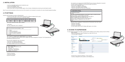
Once the card has started, proceed as indicated below: • Connect the serial cable to card’s service port and PC’s COM port (shipped with the card) • Use a terminal emulator such as PuTTY with these settings:
Bits per second Data bits Stop bits
9600
8
1
"Echo typed characters locally" option: disabled
Parity None
Flow control None
• Type admin. The main configuration menu is displayed:
3. INSTALLATION
• Use the provided MAC address label to identify the card. • Connect the ETHERNET cable. • Check the ETHERNET port indications. • Wait until the Data LED flashes regularly (approx. three minutes), indicating that card start-up has terminated correctly.
Network configuration : MAC address : 00:20:85:FD:1C:07 Mode : DHCP IP address : xxx.xxx.xxx.18 Subnet mask : 255.255.248.0 Gateway : xxx.xxx.xxx.1
Zenith MX150 MX250 自动转换开关网络卡 50P-2035 维护与操作手册说明书

—OPERATION AND MAINTENANCE MANUALZenith Modbus Network Card 50P-2035 For MX150/MX250 (MX Version 6.0+ Only)ABB Zenith disclaims any and all liability for use of third-party application software that will be used to control the Automatic Transfer Switches.PageOverview (01)LED Indicator (01)Installation (02)Installation on the Controller (02)Termination Resistor (02)Configuring a Modbus Network Card (02)Testing a Modbus Network (03)CDP Programmable Exercisers (03)CDT Exercisers (3)Operation (04)Setting System Time (04)Operation with In-Phase Monitor (04)Operation Under Battery Backup (04)Appendix A – Read Only Register List......................................................................................................................05-12 Appendix B – Read/Write Register List................................................................................................................13-14 Appendix C – Modbus Network Card. (15)Appendix D – Connections for Configuring and Testing the Modbus Card (16)Appendix E – RS485 Multi-Drop Connection (17)Appendix F – Installation of Modbus Card on Controller (18)Appendix G – Modbus Protocol Illustration......................................................................................................19-21 Appendix H – Configuring Controller for Modbus (MX150/250). (22)Bill of Materials (23)Components for the Modbus Option (ZNET250M) (23)Components for the Modbus Card Configuration (23)Troubleshooting (24)Testing a Modbus NetworkThe Modbus network can be tested using the compo-nents in the Modbus Configuration package (ABB Zenith Part # 50P-1124). Reference Appendix D for connections.1.If testing a network consisting of more than onecard, make sure that all of the cards are daisychained as shown in Appendix E. Verify that allModbus cards are in the run mode (jumper J4 onthe Modbus card must not be installed).Termination jumper (J6) is only installed on thelast card on the network daisy chain.2.Connect the RS232/485 converter (ABB Zenith Part# 50W-1208) to the PC that contains theConfiguration software (ABB Zenith Part # 50P-1111).A cable needs to be connected to the RS485 connectorof the Modbus card and the RS485 connector of theRS232/485 connector. Check to make sure that thepolarity connections are correct. (See Appendix D)3.Run the Configuration software on the PC.4.Press the TEST button and then verify that the settingsin the Communication Settings section match the settings of the Modbus network. If necessary, make changesto the settings and click the NEXT button.5.The software will now scan the network and displaythe serial number of all controllers, which have theModbus card attached. The user can select any ofthe listed serial numbers and execute a load test ona controller associated with the selected serial num-ber, but only one controller can be tested at a time. CDP Programmable ExercisersCDP Programmable Exercisers are an option on theMX150 and MX250. They allow the controller to be pro-grammed to automatically test the generator and Automatic Transfer Switch. Up to seven exercisers can be programmed to run on a daily, 7 day, 14 day, or 28 day basis; or up to 24 exercisers can be programmed to run on a yearly basis.Configuration information regarding CDP Programmable Exercisers is available in the Exerciser Configuration Register (Holding Register 40063):Bit 0 of the Exerciser Configuration Register (Coil 81) indicates whether the controller is configured for CDTor CDP Programmable Exercisers. A one means the con-troller is configured for CDP Programmable Exercisers. Bit 2 of the Exerciser Configuration Register (Coil 82) indicates whether or not the CDP Programmable Exercisers can be configured to run under load (trans-fer the ATS to the generator). A zero indicates that exercisers can only run No-Load. A one indicates that exercisers can be programmed to run Load or No-Load. Holding Registers 40101 through 40110 are provided to control and report the status of the CDP Exercisers. These registers contain valid data only if the controller is configured for CDP Exercisers. If the controller is config-ured for CDP Exercisers, then Holding Register 40063, Bit 0 (Coil 81) will be set to 1.Reading the CDP Exerciser Holding RegistersThe controller may be programmed for multiple exer-cisers, depending on the status of the Exerciser Schedule Selection. All data relevant to every exerciser is read out through Holding Registers 40101 through 40110. These registers will contain data describing one exerciser at a time. The value of Holding Register 40101, “Exerciser Record Pointer”, determines which exerciser is presently being displayed in Holding Registers 40102 through 40109.To read the contents of a different exerciser, the Exerciser Record Pointer must be written. For example, in order to read data about CDP Exerciser #3, the Exerciser Record Pointer must be set to 3.The controller will automatically place all exercisers in chronological order.CDT ExercisersCDT Exercisers are a standard feature of the MX150 and MX250 (unless replaced by CDP Programmable Exercisers). They allow the controller to be pro-grammed to automatically test the generator and Automatic Transfer Switch. The exerciser will run at the same time of day on a daily, 7 day, 14 day, or 28 day basis. Programming of the CDT Exerciser can be done only at the HMI on the front panel of the MX150 or MX250.Configuration information regarding CDT Exercisers is available in the Exerciser Configuration Register (Holding Register 40063):Bit 0 of the Exerciser Configuration Register (Coil 81) indicates whether the controller is configured for CDT or CDP Programmable Exercisers. A zero means the controller is configured for CDT Exercisers. Conversely, bit 1 implies the controller is configured for the CDP Exerciser.Bit 1 of the Exerciser Configuration Register (Coil 82) indicates whether or not the CDT is configured for Load Exercises. A one indicates the CDT will run a Load Exercise. A zero indicates the CDT will run a No-Load Exercise.The upper byte of the Exerciser Configuration Register (bits 15 through 8) indicates the CDT Exerciser Run Duration, in minutes.Setting System TimeHolding Registers 40094 through 40099 are provided to control and report the status of the controller’s System Time. Reading Holding Register 40094 through 40099 will report the current Hour, Minute, Day, Month, Year, and Day of Week to which controller’s internal clock is currently set.Writing the System Time Holding Registers Holding Registers 40094 through 40098 must be written using a Write Multiple Holding Register Command (Function Code 16). This is to ensure that the data con-tained in these registers is a complete ordered set. Any attempt to write Holding Registers 40094, 40095, 40096, 40097, or 40098 with a Write Single Holding Register Command (Function Code 6), or a Write Multiple Holding Register Command (Function Code 16) that does not include the entire range of 40094 - 40098, will result in an Illegal Data Address exception response from the Modbus Card.Note: Holding Register 40099, “System Time-Day of Week” is Read Only. The value of this register is auto-matically computed and updated by the controller, based on the calendar date.Operation with In-Phase Monitor Special consideration is required if the controller is con-figured with the In-Phase Monitor. Most Modbus net-work data and control are unavailable while the In-Phase Monitor is waiting for phase synchronization. The Modbus Network Card will return a “Slave Device Busy”exception code (06h) to all Modbus queries, except for queries to the System Busy Status Register (Holding Register 40112) or the System Busy Control Register (Holding Register 40113).If the Modbus Network Card returns a Slave Device Busy exception code, information about the source of the busy condition may be available in the System Busy Status Register (Holding Register 40112). If Bit 0 of the System Busy Status Register (Coil 105) is set to one, the controller is busy waiting for phase synchronization.If the controller is busy waiting for phase synchroniza-tion, the In-Phase Monitor may be bypassed over the Modbus network by performing the following sequence: Warning:EXTREME CAUTION must be used when bypassing the In-Phase Monitor! Transferring between sources that are not in phase synchronization may cause unexpected operation, resulting in damage to plant equipment and personnel.1. Set Bit 0 of the System Busy Control Register (Coil 113) to one. This is a request by the Modbus user to bypass the In-Phase Monitor.2. Once an In-Phase Monitor bypass has been requested, and the controller has been waiting for phase synchro-nization for more than one minute, the controller will request confirmation of the In-Phase Monitor bypass. This request is indicated by a one in Bit 1 of the System Busy Status Register (Coil 106).3. To confirm the request to bypass, set Bit 1 of the System Busy Control Register (Coil 114) to one.The controller will bypass the In-Phase Monitor. Note:The In-Phase Monitor bypass feature is an inter-locked command-and-confirm mechanism. The Modbus Card will not allow the Confirm Bypass control bit (Coil 114) to be set before the controller has set Ready to Confirm Bypass status bit (Coil 106). If a write request is received to set Coil 114 before the controller has set Coil 106, an Illegal Data Value error code will be returned. Bypass Pending ExerciserBit 0 (Coil 121) is the Bypass Pending Exerciser bit. The MX Platform performs a logic-OR with this bit and the BPASS EXER key on the HMI. A 1 in Bit 0 bypasses the pending exerciser; a 0 does nothing.Cancel BypassBit 1 (Coil 122) is the Cancel Bypass bit. The MX Platform performs a logic-OR this bit with the CANCL BPASS key on the HMI. A 1 in Bit 1 cancels the Bypass Pending Exerciser. A 0 in this bit position does nothing. The Bypass Pending Exerciser Bit works different, between a Timer Exerciser and Clock Exerciser, depending on the state of Exerciser Type (Holding Register 40063, Bit 0, Coil 81). When Coil 81 = 0 (Timer Exerciser), if Coil 121 is set to 1, the Timer Exerciser will be bypassed until the Cancel Bypass Bit (Coil 122) is set to 1. When Coil 81 = 1 (Clock Exerciser), if Coil 121 is set to 1, only the exerciser that is pending at the time gets bypassed, and the exerciser only gets bypassed once. The Controller waits for Coil 121 to reset to a 0 before a subsequent bypass can be performed. Operation Under Battery Backup The controller can be powered from an external 12-volt battery in the event that neither S1 nor S2 are available. While the controller is on external battery backup, data will still be available over the Modbus Networkas noted below.While the controller is running on external battery backup, data regarding ATS position and limit switch inputs may be invalid if both S1 and S2 sources are lost. Therefore, if Bits 6 and 7 of Holding Register 40001,or Coils 7 and 8, are both zero, the following Modbus network data may not be reliable:•Automatic Transfer Relay –Holding Register 40001, Bit 0 or Coil 1•SN Limit Switch –Holding Register 40002, Bit 0 or Coil 9•SE Limit Switch –Holding Register 40002, Bit 1 or Coil 10•SNO Limit Switch –Holding Register 40002, Bit 2 or Coil 11•SEO Limit Switch –Holding Register 40002, Bit 3 or Coil 12•S1 Position Status –Holding Register 40004, Bit 9 or Coil 34•S2 Position Status –Holding Register 40004, Bit 10 or Coil 352 4 94104 d n o c e S 4 t n e v E 05104 r u o H 4 t n e v E 15104 e t u n i M 4 t n e v E 25104h t n o M 4 t n e v E 35104 h t n o M f o y a D 4 t n e v E 45104r a e Y 4 t n e v E 551042 5 65104 d n o c e S 5 t n e v E 75104 r u o H 5 t n e v E 85104 e t u n i M 5 t n e v E 95104h t n o M 5 t n e v E 06104 h t n o M f o y a D 5 t n e v E 16104r a e Y 5 t n e v E 261042 6 36104 d n o c e S 6 t n e v E 46104 r u o H 6 t n e v E 56104 e t u n i M 6 t n e v E 66104h t n o M 6 t n e v E 76104 h t n o M f o y a D 6 t n e v E 86104r a e Y 6 t n e v E 961042 7 07104 d n o c e S 7 t n e v E 17104 r u o H 7 t n e v E 27104 e t u n i M 7 t n e v E 37104h t n o M 7 t n e v E 47104 h t n o M f o y a D 7 t n e v E 57104r a e Y 7 t n e v E 671042 e l b a T e e S 8 t n e v E r o f n o s a e R 77104 d n o c e S 8 t n e v E 87104 r u o H 8 t n e v E 97104 e t u n i M 8 t n e v E 08104h t n o M 8 t n e v E 18104 h t n o M f o y a D 8 t n e v E 28104r a e Y 8 t n e v E 381042 9 48104 d n o c e S 9 t n e v E 58104 r u o H 9 t n e v E 68104 e t u n i M 9 t n e v E 78104h t n o M 9 t n e v E 88104 h t n o M f o y a D 9 t n e v E 98104r a e Y 9 t n e v E 091042 01 19104 d n o c e S 01 t n e v E 29104 r u o H 01 t n e v E 39104 e t u n i M 01 t n e v E 49104h t n o M 01 t n e v E 59104 h t n o M f o y a D 01 t n e v E 69104r a e Y01 t n e v E791042 11 89104 d n o c e S 11 t n e v E 99104 r u o H 11 t n e v E 00204 e t u n i M 11 t n e v E 10204h t n o M 11 t n e v E 20204 h t n o M f o y a D 11 t n e v E 30204r a e Y 11 t n e v E 402042 21 50204 d n o c e S 21 t n e v E 60204 r u o H 21 t n e v E 70204 e t u n i M 21 t n e v E 80204h t n o M 21 t n e v E 90204 h t n o M f o y a D 21 t n e v E 01204r a e Y 21 t n e v E 112042 31 21204 d n o c e S 31 t n e v E 31204 r u o H 31 t n e v E 41204 e t u n i M 31 t n e v E 51204h t n o M 31 t n e v E 61204 h t n o M f o y a D 31 t n e v E 71204r a e Y 31 t n e v E 812042 41 91204 d n o c e S 41 t n e v E 01204 r u o H 41 t n e v E 12204 e t u n i M 41 t n e v E 22204h t n o M 41 t n e v E 32204 h t n o M f o y a D 41 t n e v E 42204r a e Y 41 t n e v E 522042 51 62204 d n o c e S 51 t n e v E 72204 r u o H 51 t n e v E 82204 e t u n i M 51 t n e v E 92204h t n o M 51 t n e v E 03204 h t n o M f o y a D 51 t n e v E 13204r a e Y51 t n e v E232042.Registers 40031 and 40032 contain unscaled frequency values. In order to obtain a full-scale frequency value, use the following formula: Scales Frequency + (20,000,000 / Period Count)Notes:1.Registers 40025 - 40030 contain unscaled voltage values In order to obtain a full-scale voltage value, use the following formula:Voltage = (A/D Raw Value / 192) x Full Scale Voltage (Register 40021)RS485 Multi-Drop ConnectionFor a detailed specification of the Modbus protocol, reference the Modicon website address.The Modbus protocol provides the internal standard for parsing messages. During communications on a Modbus network, the protocol determines how each slave will know its device address, recognize a message addressed to it, determine the kind of action to be taken, and extract any data or other information contained in the message. If a reply is required, the slave will construct the reply message and send it using Modbus protocol.The following is a brief description of the Modbus com-mands supported by the Modbus Network Card. Each command consists of the following:• a sample query message that is sent out by the master device to the designated slave•the slave’s reply message to the master device The query and reply messages show how the information is packeted and sent out using the Modbus Protocol. Each query message consists of the following:•Slave Address– address of the slave you wish to establish communications with.•Function Code– code that lets the slave know what command is being requested, e.g. read coil,write single coil.•Starting Address High/Low Order– high and low byte of the address the master reads from orwrites to. Coils and Registers are addressed start-ing at 0. For instance Coil 1 is address 0 andRegister 40001 is address 0.•Error Check Field– contains either a CRC(RTU mode) or LRC(ASCII mode) error check value. The query message for specific functions requires some of the following information:•Number of Data Points High/Low Order– high and low byte of the number of addresses themaster wants to read.•Data High/Low Order– high and low byte of the data that will be written to the slave device.•Number of Coils High/Low Order– high and low byte for the number of coils to force ONor OFF.•Number of Regs High/Low Order– high and low byte for the number of registers to preset.•Byte Count– is the number of data bytes which are sent to the slave.Modbus Protocol IllustrationThese query and reply messages are for both RTU andASCII modes depending on whether the Error CheckField contains a CRC or LRC respectively. Each valuein the query message is a hexadecimal value.Figure G3 – Read Holding Register Query MessageWrite Multiple Coils (Function Code 15)Forces each coil in a sequence of coils to either ON or OFF . The requested ON /OFF states are specified by con-tents of the query data field. A logical ‘1’ in a bit position of the field requests the corresponding coil to be ON and a logical ‘0’ requests it to be OFF . Coils are addressed starting at 0. For examples coil 1 is addressed as 0.QueryThe following example is a request to force a series of six-teen coils starting at coil 41 (addressed as 40, or 28 hex)in slave device 9.The query data contents consist of two bytes: 3C 9B hex (0011 1100 1001 1011 binary). The binary bits corre-spond to the coils in the following way:The first byte sent (3C hex) addresses coils 41-48, with the least significant bit addressing coil 41. The second byte sent (9B hex) addresses coils 49-56, with the least significant bit addressing coil 49.Modbus Protocol Illustration (cont’d)Figure G5 – Write Single Coil Query MessageResponseThe slave’s normal response to the Write Single Coil query is to return the original message after the coil state has been altered.Figure G6 – Write Single Coil Response MessageFigure G7 – Write Single Holding Register Query MessageResponseThe slave’s response to the Write Single HoldingRegister query is to return the original message after the registers have been altered.Figure G8 – Write Single Holding Register Response MessageCoil:48474645444342415655545352515049Bit:0111111111Write Single Holding Register (Function Code 06)This function allows the master to modify the contents of one holding register.QueryFigure G7is an example of a request to preset register 40041 (Normal Pickup Voltage) to 92 (00 5C hex) in slave device 17.Figure G9 – Write Multiple Coils Query MessageModbus Protocol Illustration (cont’d)Figure G10 – Write Multiple Coils Response MessageFigure G11 – Write Multiple Registers Query MessageFigure G12 – Write Multiple Registers Response MessageConfiguring Controller for Modbus MX150/250ABB Zenith Controls, Inc.305 Gregson Drive Cary, NC 2751124-hour support:ABB Technical Services +1 (800) 637-1738**********************C C 303025M 0201 08/19。
3G150M 用户手册

3G150M 用户手册目录第1章产品简介 21.1产品简介21.2 产品规格 21.3 包装清单 21.4 面板指示灯及接口说明 3第2章产品硬件安装 32.1 硬件安装 32.2 网络连接拓扑 3第3章如何登录到设备 53.1 使用有线网卡连接 53.2 使用无线网卡连接 63.3 登陆WEB设置界面 6第4章工作模式设置向导74.13G路由器模式设置向导 74.2无线接入点模式设置向导84.3无线信号放大模式设置向导84.4 无线路由器模式设置向导9第5章高级设置95.1 LAN设置 95.2 WAN 口设置105.3 MAC地址克隆115.4 域名服务器12第6章无线设置126.1无线基本设置126.2 无线安全设置 136.3 高级设置 146.4 WPS设置 146.5 WDS设置156.6 无线访问控制 156.7 连接状态 15第7章DHCP服务器157.1 DHCP服务设置157.2 DHCP列表与绑定16第8章虚拟服务器168.1 端口段映射168.2 DMZ主机178.3 UPNP设置17第9章带宽控制17第10章3G流量统计18第11章安全设置1811.1客户端过滤1811.2 URL过滤1911.3 MAC地址过滤1911.4防网络攻击2011. 5远程WEB管理2011.6 W AN口PING 20第12章路由设置20第13章系统工具2113.1时间设置2113.2 动态DNS 2113.3 备份/恢复设置2113.4 恢复出厂设置2213.5 软件升级2213.6 重启路由器2213.7 修改登录密码2313.8 系统日志2313.9 退出登录23附录一设置电脑自动获取IP地址23附录二设备加密后如何设置网卡24附录三名词解释25附录四常见问题解答26附录五3G上网卡兼容清单V 0.5 27第1章产品简介1.1产品简介感谢您购买3G150M便携式3G无线路由器。
3G150M是一款支持3G网络接入的150Mbps无线设备,基于最新的IEEE802.11n标准,提供高达150Mbps的无线速率,是普通802.11g产品的3倍以上,并且兼容IEEE802.11b/g标准的网络设备。
Moxa ioThinx 4510 Series商品介绍说明书

ioThinx4510SeriesAdvanced modular remote I/O adapter with built-in serial portsFeature and Benefits•Easy tool-free installation and removal•Easy web configuration and reconfiguration•Built-in Modbus RTU gateway function•Supports Modbus/SNMP/RESTful API•Supports up to32I/O modules•-40to75°C wide operating temperature model availableCertificationsIntroductionThe ioThinx4510Series is an advanced modular remote I/O product with a unique hardware and software design,making it an ideal solution for a variety of industrial data acquisition applications.The ioThinx4510Series has a unique mechanical design that reduces the amount of time required for installation and removal,simplifying deployment and maintenance.In addition,the ioThinx4510Series supports Modbus RTU Master protocol for retrieving field site data from serial meters and also supports OT/IT protocol conversion.Easy Tool-Free Installation and RemovalThe ioThinx4500Series has a unique mechanical design that reduces the amount of time required for installation and removal.In fact,screwdrivers and other tools are not required for any part of the hardware installation,including mounting the device on a DIN-rail,as well as connecting the wiring for both communication and I/O signal acquisition.Furthermore,no tools are required to remove the ioThinx from a DIN-rail.Removing all of the modules from a DIN-rail is also easy using the latch and release tab.Easy Web Configuration/ReconfigurationFor modular remote I/O setups,one of the greatest difficulties is duplicating configuration settings to the current modules with different module combinations.After adding,moving,or deleting one of the modules,settings of the unchanged modules,including the Modbus address and RESTful APIs to the upper software,need to be reconfigured.The ioThinx4510’s user-friendly web configuration tool was designed specifically to make configuration and reconfiguration easy;no reconfiguration efforts are required for the unchanged modules.In addition,the ioThinx4510’s web interface supports module/channel unique names.This feature also applies to Modbus TCP and RESTful API,saving users considerable amounts of time on development and deployment.Built-In Modbus RTU Gateway FunctionThe ioThinx4510supports Modbus RTU Master for retrieving field site data from serial meters.After collecting data,users can convert serial data to a variety of protocols,including Modbus TCP,SNMP,and RESTful,allowing users to get field site data in their protocol of choice.This two-in-one design reduces system complexity and the amount of space required in the network topology,as well as overall installation time.In addition, you can extend the useful life of legacy devices by connecting them to Ethernet and accessing the devices using a preferred protocol.I/O to IT/OT Protocol ConversionThe ioThinx4510does just what you need by supporting the mostoften-used protocols for retrieving I/O data.Most IT engineers useSNMPv1/v2c/v3or RESTful API protocols,but IA engineers are morefamiliar with Operational Technologies(OT),such as Modbus.TheioThinx4510makes it possible for both IT and OT engineers toconveniently retrieve data from the same I/O device.The ioThinx4510speaks several different protocols,including Modbus TCP for OTengineers,as well as SNMP and RESTful API for IT engineers.TheioThinx4510retrieves I/O data and converts the data to any of theseprotocols,allowing you to get your applications connected easily andeffortlessly.SpecificationsInput/Output InterfaceButtons Reset buttonExpansion Slots Up to321Isolation3k VDC or2k Vrmspatible with the ioThinx4500Series(45MR)Modules onlyEthernet Interface10/100BaseT(X)Ports(RJ45connector)2,1MAC address(Ethernet bypass)Magnetic Isolation Protection 1.5kV(built-in)Ethernet Software FeaturesConfiguration Options Web Console(HTTP),Windows Utility(IOxpress) Industrial Protocols Modbus TCP Server(Slave),RESTful API,SNMPv1/v2c/v3 Management SNMPv1/v2c/v3,DHCP Client,IPv4,HTTP,UDP,TCP/IP Serial InterfaceConnector Spring-type Euroblock terminalSerial Standards RS-232/422/485No.of Ports1x RS-232/422or2x RS-485(2wire)Baudrate1200bps to115.2kbpsFlow Control RTS/CTSParity None,Even,OddStop Bits1,2Data Bits8Serial SignalsRS-232TxD,RxD,RTS,CTS,GNDRS-422Tx+,Tx-,Rx+,Rx-,GNDRS-485-2w Data+,Data-,GNDSerial Software FeaturesIndustrial Protocols Modbus RTU Client(Master)System Power ParametersPower Connector Spring-type Euroblock terminalNo.of Power Inputs1Input Voltage12to48VDCPower Consumption800mA@12VDCOver-Current Protection1A@25°COver-Voltage Protection55VDCOutput Current1A(max.)Field Power ParametersPower Connector Spring-type Euroblock terminalNo.of Power Inputs1Input Voltage12/24VDCOver-Current Protection 2.5A@25°COver-Voltage Protection33VDCOutput Current2A(max.)Physical CharacteristicsWiring Serial cable,16to28AWGPower cable,12to26AWGStrip Length Serial cable,9to10mmPower cable,12to13mmHousing PlasticDimensions42.3x99x75mm(1.67x3.9x2.95in)Weight173.5g(0.382lb)Installation DIN-rail mountingStandards and CertificationsEMC EN55032/24EMI CISPR32,FCC Part15B Class AEMS IEC61000-4-2ESD:Contact:4kV;Air:8kVIEC61000-4-3RS:80MHz to1GHz:3V/mIEC61000-4-4EFT:Power:2kV;Signal:1kVIEC61000-4-5Surge:Power:2kV;Signal:1kVIEC61000-4-6CS:10VIEC61000-4-8PFMFShock IEC60068-2-27Vibration IEC60068-2-6Environmental LimitsOperating Temperature ioThinx4510:-20to60°C(-4to140°F)ioThinx4510-T:-40to75°C(-40to167°F) Storage Temperature(package included)-40to85°C(-40to185°F)Ambient Relative Humidity5to95%(non-condensing)Altitude Up to4000m2DeclarationGreen Product RoHS,CRoHS,WEEEMTBFTime1,451,040hrsStandards Telcordia SR332WarrantyWarranty Period5yearsDetails See /warranty2.Please contact Moxa if you require products guaranteed to function properly at higher altitudes.Package ContentsDevice1x ioThinx4510Series remote I/O Installation Kit1x terminal block,5-pin,5.00mm1x terminal block,5-pin,3.81mm Documentation1x quick installation guide1x warranty card DimensionsTop/Side/Bottom PanelsSide CoverOrdering InformationModel Name Ethernet Interface Serial Interface No.of Support I/O Modules Operating Temp. ioThinx45102x RJ45RS-232/RS-422/RS-48532-20to60°C ioThinx4510-T2x RJ45RS-232/RS-422/RS-48532-40to75°C Accessories(sold separately)IO Modules45MR-1600Module for the ioThinx4500Series,16DIs,24VDC,PNP,-20to60°C operating temperature45MR-1600-T Module for the ioThinx4500Series,16DIs,24VDC,PNP,-40to75°C operating temperature45MR-1601Module for the ioThinx4500Series,16DIs,24VDC,NPN,-20to60°C operating temperature45MR-1601-T Module for the ioThinx4500Series,16DIs,24VDC,NPN,-40to75°C operating temperature45MR-2404Module for the ioThinx4500Series,4relays,form A,-20to60°C operating temperature45MR-2404-T Module for the ioThinx4500Series,4relays,form A,-40to75°C operating temperature45MR-2600Module for the ioThinx4500Series,16DOs,24VDC,sink,-20to60°C operating temperature45MR-2600-T Module for the ioThinx4500Series,16DOs,24VDC,sink,-40to75°C operating temperature45MR-2601Module for the ioThinx4500Series,16DOs,24VDC,source,-20to60°C operating temperature45MR-2601-T Module for the ioThinx4500Series,16DOs,24VDC,source,-40to75°C operating temperature45MR-2606Module for the ioThinx4500Series,8DIs,24VDC,PNP,8DOs,24VDC,source,-20to60°C operatingtemperature45MR-2606-T Module for the ioThinx4500Series,8DIs,24VDC,PNP,8DOs,24VDC,source,-40to75°C operatingtemperature45MR-3800Module for the ioThinx4500Series,8AIs,0to20mA/4to20mA,-20to60°C operating temperature 45MR-3800-T Module for the ioThinx4500Series,8AIs,0to20mA/4to20mA,-40to75°C operating temperature 45MR-3810Module for the ioThinx4500Series,8AIs,-10to10V/0to10V,-20to60°C operating temperature45MR-3810-T Module for the ioThinx4500Series,8AIs,-10to10V/0to10V,-40to75°C operating temperature45MR-6600Module for the ioThinx4500Series,6RTDs,-20to60°C operating temperature45MR-6600-T Module for the ioThinx4500Series,6RTDs,-40to75°C operating temperature45MR-6810Module for the ioThinx4500Series,8TCs,-20to60°C operating temperature45MR-6810-T Module for the ioThinx4500Series,8TCs,-40to75°C operating temperaturePower Modules45MR-7820Module for the ioThinx4500Series,potential distributor module,-20to60°C operating temperature 45MR-7820-T Module for the ioThinx4500Series,potential distributor module,-40to75°C operating temperature©Moxa Inc.All rights reserved.Updated Nov12,2018.This document and any portion thereof may not be reproduced or used in any manner whatsoever without the express written permission of Moxa Inc.Product specifications subject to change without notice.Visit our website for the most up-to-date product information.。
Edimax EW-7722UTn V3 无线USB网卡技术参考手册说明书

EW-7722UTn V3
OVERVIEW EW-7722UTn V3 is a nano USB wireless adapter that supports maximum range and speed. Despite the size, this tiny USB adapter supports higher data rate of up to 300Mbps when connecting with wireless 802.11n device which is 5 times faster than your normally 11g connection. Just plug it into a computer's USB port and enjoy incredible high-speed wireless network access. This is one of the easiest, fastest and most valuable way to upgrade your internet experience.
• Windows 7/8/8.1/10 • Mac OS 10.11 ) • Linux OS (Fedora & Ubuntu )
* Additional version information will be announced on the EDIMAX website download section.
Multi-Language | Easy Setup Wizard The included 16 languages easy setup wizard and friendly UI will walk you through the EW-7722UTn V3 wireless network configuration.
MAX260 用户手册(全文)3G Router

EVDO 3G Router 用户手册目录1 简介 (1)2 硬件描述与设备安装 (2)2.1 硬件描述 (2)2.1.1 前面板与LED状态说明 (2)2.1.2 后面板及其接口说明 (3)2.2 硬件安装 (4)2.2.1 安装要求 (4)2.2.2 安装前准备 (4)2.2.3 设备安装 (5)2.2.4 操作范围 (5)3 Web页面配置管理 (6)3.1 登录前准备 (6)3.2 登录 (7)3.3 系统状态 (7)3.3.1 设备信息 (7)3.3.2 网络侧信息 (8)3.3.3 用户侧信息 (8)3.4 网络 (9)3.4.1 宽带设置 (9)3.4.2 DHCP设置 (10)3.4.3 WLAN配置 (11)3.5 安全 (15)3.5.1 广域网访问设置 (15)3.5.2 防火墙 (16)3.5.3 MAC过滤 (16)3.5.4 端口过滤 (17)3.6 管理 (20)3.6.1 用户管理 (20)3.6.2 设备管理 (21)3.7 帮助 (21)4 常见问题解答 (23)关于用户手册此文档包含的信息主要是关于如何安装和配置EVDO 3G Router。
用户手册的组织此用户手册的组织如下表:章节描述第 1 章:简介简要介绍EVDO 3G Router。
第1 2 章:硬件描述与设备安装描述EVDO 3G Router的前后面板以及硬件安装程序。
第 3 章:Web页面配置管理描述如何运用Web配置工具配置EVDO 3GRouter。
第 4 章:常见问题解答描述在使用过程中可能会遇到的问题及解决方法。
特性支持IEEE802.3和IEEE802.3u支持高达54Mbps的数据传输速率支持WEP和WPA数据安全传输支持DHCP Server和Client功能支持静态路由功能支持出厂设置复位功能支持虚拟服务器功能支持DMZ功能支持Web界面管理支持防火墙功能支持系统状态显示支持配置文件备份和恢复功能1 简介尊敬的用户:感谢您选择EVDO 3G Router!EVDO 3G Router是一款高集成度的,符合IEEE802.11b/g标准的高端多合一综合接入设备。
网卡使用手册
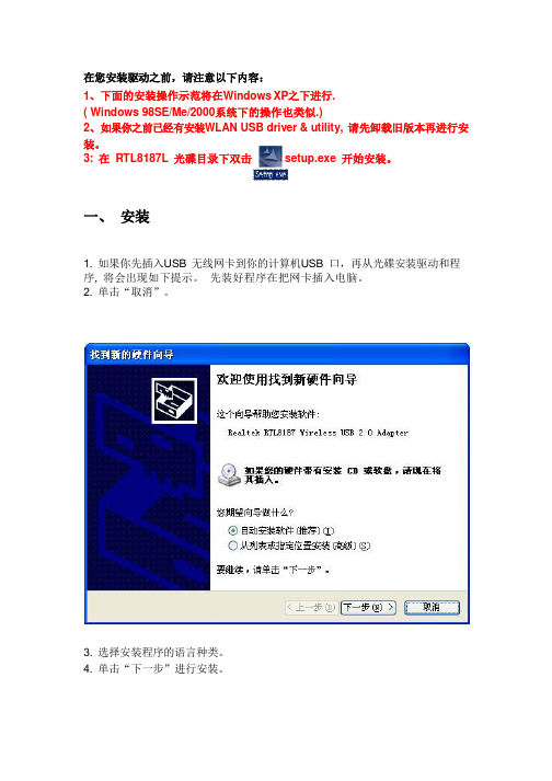
在您安装驱动之前,请注意以下内容:1、下面的安装操作示范将在Windows XP之下进行.( Windows 98SE/Me/2000系统下的操作也类似.)2、如果你之前已经有安装WLAN USB driver & utility, 请先卸载旧版本再进行安装。
3: 在RTL8187L 光碟目录下双击setup.exe 开始安装。
一、安装1. 如果你先插入USB 无线网卡到你的计算机USB 口,再从光碟安装驱动和程序, 将会出现如下提示。
先装好程序在把网卡插入电脑。
2. 单击“取消”。
3. 选择安装程序的语言种类。
4. 单击“下一步”进行安装。
二、反安装A. 从“开始”菜单--->“所有程序”—>“Wireless Network Driver and Utility”选择“Uninstall ”或从“控制面板”单击“删除”(或“更改/删除”) 去移除USB 无线网卡驱动。
B. 如果你想要卸载USB 无线网卡驱动,单击“确定”。
C. 然后单击“完成”去完成反安装。
四、创建基本的网络连接按下面的指导去创建网络连接, 使用“Wireless LAN Utility ”去配置你的无线网 络设置。
注意: 如果Windows XP 用户想要使用“Wireless LAN Utility ”去配置你的无线网络,请先禁用你原来的Windows XP 无线配置程序(Wireless Zero Configuration 服务)。
1. 在你的桌面双击 图标开始“Wireless LAN Utility ” 或在任务栏系统托盘单击图标。
1. 在桌面双击图标开始“Wireless LAN Utility”或单击任务栏系统托盘图标。
2. 单击“可用网络”选项卡去查看可用的无线网络,可以单击“刷新”按钮来获取最新的可用网络资讯。
双击你将要连接的无线网络加入或创建配置文件,也可以通过“添加到配置文件”按钮来达到同样效果。
达实TCP消费机说明书WIFI

手册用途·本手册包含DAC XF4870、DAC XF4970产品功能介绍、产品说明、产品调试、常见故障及诊断和技术参数等内容,供用户和技术人员参考使用,用户在使用本产品前务必先阅读本手册。
·本使用手册版权归达实智能股份有限公司所有。
·产品的发行和销售由原始购买者在许可协议条款下使用。
未经达实智能股份有限公司允许,任何单位和个人不得将该手册全部或部分复制、或者还原成其它机器可读形式的电子媒介。
·本手册若有任何修改恕不另行通知。
·本手册最终解释权归达实智能股份有限公司所有。
注意事项及使用要求在使用本设备时,务必应遵循下述基本注意事项:1、在使用初始化功能时,应先确认机内是否有未上传的消费数据,否则先将消费数据采集2、刷卡消费时将卡在感应器区轻轻一晃即可,切勿用卡片拍打卡感应器。
3、经常保持消费机清洁,防止水、油烟、灰尘、腐蚀性气体等侵入机内,以免影响机器的正常工作。
4、内置后备电池,接通外部12V DC电源时便可处于浮充电状态.外部电源切断本机后备电池可应急运行4小时左右.完全充电时间为10小时左右,累计充放电次数约为300次,在浮充电状态下电池使用寿命时间为半年左右.电池为易损配件,请及时更换电池5、若本机发生故障,非专业人员不得打开机器,应与本机的供应商联系解决,也可直接联系本公司售后服务热线电话:0755-********。
6、申请技术服务时,请提供本机购货合同号、产品序列号、故障现象。
7、此产品满足电磁兼容A级,在生活环境中,距该产品一定距离内可能会造成无线电干扰。
在这种情况下,可能需要用户对其干扰采取切实可行的措施。
欢迎您使用达实智能股份有限公司DAC XF4870、DAC XF4970消费机.熟悉使用本手册后,仍遇到有技术上的问题,请及时与公司取得联系.第一章产品功能及技术参数1.1.产品简介DAC XF4870、DAC4970是达实智能股份有限公司根据市场需求开发出的一款基于CORTEX-M3开发平台的32位的高端消费机。
- 1、下载文档前请自行甄别文档内容的完整性,平台不提供额外的编辑、内容补充、找答案等附加服务。
- 2、"仅部分预览"的文档,不可在线预览部分如存在完整性等问题,可反馈申请退款(可完整预览的文档不适用该条件!)。
- 3、如文档侵犯您的权益,请联系客服反馈,我们会尽快为您处理(人工客服工作时间:9:00-18:30)。
产品使用说明书(适用于windowsXP /windows 7系统)注:Windows 7系统也建议重新安装下驱动,因为软件不断的在升级,如果确保是最新的驱动可以不用安装!目 录一、驱动安装(注:未安装驱动前,请不要插入无线网卡) (2)二、上网设置 (4)2.1 路由器上网设置 (4)2.1.1路由器常见故障排除 (8)2.2 WLAN上网设置 (9)2.2.1 WLAN常见故障排除 (11)三、信号强上网慢问题解答 (12)一、驱动安装(注:未安装驱动前,请不要插入无线网卡)1、打开光盘,双击文件夹,选择对应的系统,(这里我以Windows7系统为例)双击安装程序;2、选择,单击;3、选择,单击;3、点击,进行网卡驱动程序安装;4、如下图显示安装进行中;驱动安装完成后单击(注:有些杀毒软件可能影响安装,如安装不完全,请在安装前关闭杀毒软件)5、完成以后电脑右下角任务栏会出现驱动图标,这时驱动已经安装全部完成,然后将无线网卡插入电脑USB口,此时电脑会自动更新驱动程序,完成后驱动图标显示,证明无线网卡与电脑连接正常;(注:如果插上网卡还是显示灰色图标,证明无线网卡连接不正常,1、请检查网卡是否插好;2、网卡数据线为5米以上的,请检查数据线是否插在台式机的前面2个USB口,如果是,请插台式机后面的USB口;3、网卡数据线为5米以上的还需检查是否电脑供电不足引起?解决方案请查看第8页,第5项)二、上网设置2.1 路由器上网设置1、双击电脑右下角任务栏驱动图标进入设置界面,(注:也可以点击开始菜单,选择进入)2、点击放大镜按钮,搜索周边的无线网络信号;点刷新按钮,刷新周边的无线网络信号;(注:刷新时,多刷新几次,定向网卡注意调整方向)3、再单击鼠标右键,选择“以信号强度排序”,这时搜索到的网络信号会从高到低排列出来;4、找到自己的路由器名称,这里我选择,点击加入连线设定5、点2次绿色箭头,进入下一步操作;6、输入路由器对应的密码,单击绿色箭头,进入下一步操作;点激活按钮,激活网络连接!(输入密码时要正确的输对密码,注意大小写字母。
错误的密码输入会造成不能连接网络或者不能自动获取IP地址)7、此时网络连接成功;(注:网络名称前面打勾了,证明添加连线成功)此时IP地址为软件自动获取,连接成功即可正常高速上网了。
2.1.1路由器常见故障排除1、网卡可以连上去,但容易掉线?1.禁用笔记本自带的网卡和其它的一些上网设备;2. 检查计算机硬件设备管理中,网卡驱动工作是否正常,如不正常,请重新更新驱动程序;3.信号不稳定,建议调整网卡角度;(注:定向网卡正面朝向信号源的方向)4.关闭电脑后台占用带宽高的应用程序和进程;5.检查计算机硬件设备管理中,是否停用无线网卡,如停用,请重新启用;6.检查无线路由器工作是否异常,如异常,请更换无线路由器;7.检查无线路由器是否禁止SSID广播,如禁止,请启用;8.请靠近无线路由器,再尝试是否能搜索到无线网络;2、关于连接受限制,能连接上但上不了网等情况?1.检查网卡配置的加密方式和密码是否和无线路由器配置完全一样;2.信号还是不稳定,连接不上,请靠近无线路由器重新尝试连接;(注:定向网卡正面朝向信号源的方向)3.获取不到IP地址,查看电脑否启动DHCP服务和DNS服务,查看无线路由是否开启DHCP服务器;4.查看路由器是否设置了MAC地址过滤或绑定了IP;如过滤了或绑定了IP,请取消,然后重启路由器,再清空以前的无线网络信息,重新搜索可用连接;5.重启无线路由器;6.正常连接上路由,获取到IP地址不能上网,请检查路由是否是联网状态或者查看地址是否被限制,有部分朋友问为什么连接正常还上不了网,网卡显示连接正常只能代表您的电脑无线网卡和路由是连接正常,不能代表你的路由和互联网是否联通;3、搜索到无线网络,但无法正常连接?1.检查无线路由器是否配置了禁止无线主机接入,如禁止,请取消;2.检查无线网络的信号强度是否较弱,如较弱,请靠近无线路由器重新尝试连接;3.检查无线路由器工作是否异常,如异常,请更换无线路由器;4、网卡没有发送和接收数据包?1.重新获取IP,重新连接。
2.修复网络连接。
3.检查系统有没有中毒或中木马等,用杀毒软件杀下毒。
5、驱动图标一会闪一会退,不稳定、供电不足?其实供电不足分为2种:第1种:电脑太老引起的供电不足,这种情况一般是电脑的USB接口不是USB 2.0接口,是USB1.1,还有AMD CPU的电脑也容易引起供电不足;这种老电脑一般超过3米的都会有点带不动了;第2种:新款笔记本电脑引起的供电不足,这种情况是生产笔记本的厂家,为了使笔记本电脑的电池更耐用,而在主板这部份做了优化处理,因为我们常用的一些设备是用不到这么长的线的,如鼠标、键盘、打印机、U盘等都不会超过3米的线;所以5米USB数据线、10米USB数据线的网卡,就会出现供电不足;解决方法:在购买网卡的地方,告知是供电不足的情况,再买一个电源放大器即可解决,它的原理就是把主板优化过的这部份电路补回来!6、为什么我的是3070芯片或是7601的芯片怎么显示是2870?1.此版本驱动是雷凌很多款芯片都通用,因为3070排在后面,所以显示的是2870是正常的。
这个软件支持以下这些芯片(RT2870/ RT2770/ RT3070/ RT2070 RT3570/ RT3370/ RT8070/ RT5370/ MT7610/MT7601)2.2 WLAN上网设置1、双击电脑右下角任务栏驱动图标进入设置界面,(注:也可以点击开始菜单,选择进入)2、点击放大镜按钮,搜索周边的无线网络信号;点刷新按钮,刷新周边的无线网络信号;(注:刷新时,多刷新几次,定向网卡注意调整方向)3、再单击鼠标右键,选择“以信号强度排序”,这时搜索到的网络信号会从高到低排列出来;4、找到CMCC信号(Chinanet、Chinaunicom信号也是如此操作),这里我选择,点击加入连线设定5、点2次绿色箭头;6、再点激活按钮;此时网络连接成功;(注:网络名称前面打勾了,证明添加连线成功)此时IP地址为软件自动获取;7、打开IE浏览器,在左侧对话框输入:wlan帐号和对应的密码,点击,即可网上冲浪了!2.2.1 WLAN常见故障排除1、无法搜索到CMCC、Chinanet、Chinaunicom等无线网络:表明当地没有移动、电信、联通等无线网络覆盖,如果同一个地方以前可以搜到但是现在消失了,请确认WIFI是否已打开,已打开,请联系CMCC:10086、Chinanet:10000、ChinaUnicom: 10010客服,如果是基站的原因,48小时内会有技术人员到站点进行检查。
2、搜索到CMCC、Chinanet、Chinaunicom网络,但是连不上:请确认信号是否良好,如果信号良好,请察看IP是否设置的自动,并多连接几次。
3、CMCC、Chinanet、Chinaunicom网络显示已连接但是打开网页无法跳转:请使用Windows自带的IE浏览器,并确保windows系统正常,系统正常无法跳转请联系CMCC:10086、Chinanet:10000、ChinaUnicom: 10010客服,确认基站是否处于系统升级状态。
4、登陆显示登陆认证失败、认证被拒绝、同一账户正在认证中:非正常下线有可能导致上述情况,一般重启机器就可解决,如重启后依然不能登陆,请8小时后再试(账户被锁定一般是15分钟——8小时)。
5、显示已连接上,但上不了网、只有发送数据包没有接收数据包或无线信号好,但不能获取到IP地址,提示叹号:这种情况一般是无线信号数据堵塞,可以先断开已连接上的网络,然后再重启电脑,电脑重启后重新找到信号后再登陆,一般是可以解决。
还有一种情况是用网络的人太多造成的数据堵塞,这种情况可以过会再重新尝试登陆。
三、信号强上网慢问题解答1、何谓全向天线?全向天线,即在水平方向图上表现为360°都均匀辐射,也就是平常所说的无方向性,在垂直方向图上表现为有一定宽度的波束,一般情况下波瓣宽度越小,增益越大,全向天线一般适用于室内传输;2、何谓定向天线?定向天线是指在某一个或某几个特定方向上发射及接收电磁波特别强,而在其它的方向上发射及接收电磁波则为零或极小的一种天线,意味着天线越对准发射端,信号越稳定,采用定向发射天线是增加辐射功率的有效利用,增加保密性,最主要目的是增加抗干扰能力、增加穿透能力和信号汇聚能力,定向天线一般适用于室外或较远距离的传输;3、为何会出现信号超强,但网速极慢的问题?首先,我们需要理解到,信号强不等于网速快,因为整个接收信号的表现除了信号强之外,还有连线质量的表现,还有与你本身办理的上网套餐也有关系,上网速度慢并不是信号虚高的表现,信号强、连线品质不够好是会影响到接收的速率和稳定情况,最终导致网络接收掉包,严重影响上网速度,所以我们学习到了一个新的名词,除了信号强度之外更重要的一个信号状态名词——连线质量,接收强度+连线质量同时给力才是最无敌的信号,上网慢排除了USB供电问题之后,我们需要做的就是调整接收方位来改善连线质量了;4、那么理解之后应该如何改善连线质量?①我们首先双击电脑右下角的图标,打开驱动管理程序,点击第二个图标“连线信息”;②点击之后会出现“连线信息”的框,我们再点击第二个按钮“传输速率”;查看“连线质量”,接下来我们就可以看到信号强度和连线质量的一个状态显示了!③调整角度小贴士当我们知道了连线质量在哪里查看了之后,我们就可以根据驱动上面显示的百分比来调整网卡的角度了,聪明的您已经知道定向天线是需要调整接收角度的,越对准发射端,连线的质量越好!这时候我们将网卡尽量往高处摆放,耐心的微调接收角度,寻找你所在位置的最佳方位。
连线质量百分比越高、跳动越小那上网的质量越高,反之跳动大,百分比低就会不稳定、上网慢。
即使信号强度非常强那也是不稳定,上面图片的连接信号是近距离信号,所以连线质量是非常稳定的达到100%,并且丝毫不跳动,正因如此,所以上网速度是能达到全速的,您可以按照上面的分享方法去调整,相信您也能找到您所在的环境中最佳的接收方位;。