横河变送器YTA310 320选型手册
横河川仪 EJA530A 压力变送器 规格书
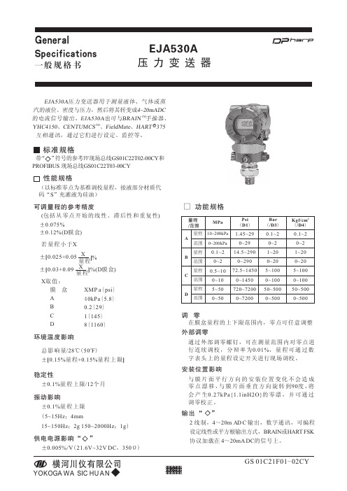
GS 01C21F01-02CY标准规格RE JA530A 压力变送器用于测量液体、气体或蒸汽的液位、密度与压力,然后将其转变成4~20mADC TM 的电流信号输出。
EJA530A 也可与BRAIN 手操器、TM YHC4150、CENTUMCS 、FieldMate 、HART 375互相通讯,通过它们进行设定、监控等。
ABCD可调量程的参考精度(包括从零点开始的线性、滞后性和重复性)若量程小于XX 取值:环境温度影响o 总影响量/28℃(50F )±[0.15%量程+0.15%量程上限]±0.1%量程上限/12个月稳定性±0.005%/V (21.6V~32V DC ,350Ω)供电电源影响“”功能规格MPaPsi (D1)Bar (/D3)2Kgf/cm (/D4)10~200kPa 调 零在膜盒量程的上下限范围内,零点可任意调整外部调零通过外部调零螺钉,可在测量范围内对零点进行连续调校,分辩率为0.01%,量程可通过数字表头上的量程设定开关进行现场调校。
安装位置影响与膜片面平行方向的安装位置变化不会造成零点漂移,与膜片面垂直方向旋转到90度,将会产生0.27kPa{1.1inH2O}的零漂,并可通过调零校正。
膜 盒A B C D XMP a {psi }40kPa {5.8}0.2{29}1{145}8{1160}振动影响±0.1%量程上限(5~15Hz ;4mm15~150Hz ;2g 150~2000Hz ;1g )0~200kPa量程范围量程范围量程范围量程范围量程/范围□ 1.45~290~2914.5~2900~29072.5~14500~1450720~72000~72000.1~20~21~200~205~1000~10050~5000~5000.1~20~21~200~205~1000~10050~5000~5000.1~20~20.5~100~105~500~50性能规格(以标准零点为基准调校量程,接液部分材质代码“S ”充灌液为硅油)输出“ ”2线制,4~20m A D C 输出,数字通讯,可编程设定线性或平方根输出方式,BRAIN 或HART FSK 协议加载在 4~20mA DC 的信号上。
E,H压力变送器选型手册
“5”代表20-28VAC / 11-40VDC; 2-行,按键
“4”代表85-250VAC; 2-行,按键
第11个符号表示可调的,软件特性“A”代表工厂设定;基本型
第12个符号表示输出,输入
“A”代表4-20mA HART +脉冲无源。
篇二:E+H压力变送器调整方法
E+H压力变送器调整方法
查询结果:
综下所属,订货号10H1H-UF0A1AG4A5AA与订货号10H1H-1F0A1AG4A4AA两个传感器可以互换,但一定要把变送器里的数据模块换过来(上面是传感器工厂标定的数据),区别仅在过程连接(第1个符号所表示)与电源(第10个符号所表示)不一样。详解如下:
第1个符号表示传感器过程连接
其中IP67:防护灰尘吸入(整体防止接触,防护灰尘渗透);防护短暂浸泡(防浸)。目前在布线行业最高实现的是IP67级别;4X:水封、尘封、防腐蚀、室内或室外用外壳(IP 66)。第8个符号表示电缆,分离型
“4”代表线圈和信号电缆长度可以在(1—200)m之间选择第9个符号表示电缆入口型号
“A”代表电缆入口为M20电缆密封套
2、认证.............................................................................................................................................. 4
2.1仪表设计............................................................................................................................. 4
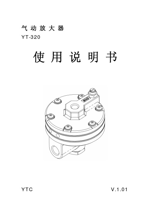
气动放大器
排气环 阀芯
阀芯弹簧
外形尺寸
调节螺丝 上盖 上方膜片 下方膜片 本体
排水盖
-3-
气动放大器
安装
YT-320
☞ 注意
产品安装和使用时请遵守如下事项。 z 必须佩戴保护装备,遵守安全事项。 z 为了避免高压气体泄漏爆炸而破坏部件或受到人身伤害,安装前请确认产品参数,不能超过 规定参数范围使用。并且为了防止受到类似伤害,请把进入气动放大器的气源进行旁通。 z 为了维护产品,请定期停止气பைடு நூலகம்放大器的动作。 z 供给气源要经过过滤净化的干燥空气,而且要使用非腐蚀性气体。 z 大气排气是通过气动放大器的侧面排气口排出。 z 请注意防止异物堵塞气路,并且为了防止排出气体沉积在密闭环境,要安装在通风好的场 所。 z 为了防止产品出现问题时高压气体直接进入执行机构,气动放大器前一定要加一个减压阀。 z 为了保证气动放大器的输出流量,请使用大容量空气过滤减压阀。
气动放大器
YT-320
使用说明书
YTC
V.1.01
气动放大器
YT-320
产品简介
气动放大器YT-320是接收安装在气动控制阀上的定位器的输出压力,以相同压力给执行机构输入 大流量的气源,加快控制阀动作速度的装置。
产品特征
z 按稳定的1:1压力供气,速度快,准确性高。 z 通过旁通调节,提高控制阀的动作安全性。 z 对于定位器的微小输入信号压力变化反应非常敏感,并能提供大流量气源给执行机构。 z 内置100微米滤网,防止异物进入。
标牌标注内容
Model : 产品的基本型号和其它选项代码。 详细的选项请参考下面内容。 Air Connection : 气源接口规格。 Max. Supply pressure : 最大输入气源压力。 Max. Signal pressure : 最大输入信号压力。 Max. Output pressure : 最大输出气源压力。
横河EJA变送器选型指南

最大工作压力
Mpa psi
3.5
500
16
2300
16
2300
16
2300
50kPa 7.25
32
4500
32
4500
3.5
500
14
2000
14
2000
接液温度 oC
—40~120
—25~80 —40~120
—40~120
基于法兰规格
见下表
基于法兰规格 —40~120
10KPa 130KPa 3000KPa
应用
差压和液位
微差压 差压和液位 (高静压)
微小流量
差压和液位 (隔膜密封)
液位开口 闭口容器 绝对压力 (真空)
压力
压力 (隔膜密封)
高压力
绝对压力 和表压力
类型
常规安装
常规安装 常规安装
内藏孔板 凸膜片 平膜片 一平一凸 平膜片 凸膜片 常规安装
常规安装 凸膜片远传 平膜片嵌入
常规安装
直接安装
横河EJA变送器选型指南
5~500
20~2000
1~10
4~40
2~100
8~400
20~210
80~830
EJA118W
M
EJA118Y
H
EJA210A
M
EJA220A
H
L
EJA310A
M
A
EJA430A
A
B
EJA438N
A
B
A10A
A
B
C EJA530A
D
2.5~100 25~500 1~100 5~500 0.67~10 1.3~130 0.03~3MPa 0.03~3MPa 0.14~14MPa 0.06~3MPa 0.46~7MPa 0.06~3MPa 0.46~14MPa 5~32MPa 5~50MPa 10~200 0.1~2MPa 0.5~10MPa 5~50MPa
4、EJA压力、差压变送器技术性能要求-横河EJA
现场条件及介质情况所提供的工业电视、DCS系统及仪表满足招标文件规定现场条件及介质情况的要求。
1、制造规范、标准及准则(1)EJA智能压力、差压变送器A.Q/CYS001-2001 EJA压力、差压变送器;B.ISO9001:2000 idt GB/T19001-2000质量管理体系标准C.GB/T 17614.1-1998 工业过程控制系统用变送器第1部分:性能评定方法。
D.GB/T 17614.2-1998 工业过程控制系统用变送器第2部分:检查和例性试验导则。
E.GB3836.1-2000 爆炸性气体环境用电气设备第1部分:通用要求。
F.GB3836.1-2000 爆炸性气体环境用电气设备第2部分:隔爆型“d”。
G.GB3836.1-2000 爆炸性气体环境用电气设备第2部分:隔爆型“d”。
H.GB3836.1-2000 爆炸性气体环境用电气设备第4部分:本质安全型“I”。
I.GB 9969.1-1998 工业产品使用说明书总则J.GB/T15464-1995 仪器仪表包装通用技术条件K.JB/T 9329-1999 仪器仪表运输,运输储存基本环境条件及试验方法L.JIS C 0920 电器设备,器具及配线材料防水试验通则(2)4、EJA压力、差压变送器技术性能要求4.1 变送器为二线制。
输出信号:4-20mA标准信号;带BRAIN协议和LCD数显;电源:24VDC。
4.2 变送器在外接负载电阻至少为500Ω时(24VDC供电),仍能正常工作。
4.3 变送器带就地数显式数字指示表,此设备是标准配置,无此表头不会影响变送器的正常工作.4.4 变送器精度高于±0.075 %。
阻尼可设置或可调。
4.5 变送器在温度变化为50℃时,漂移量不超过最大量程的0.1%。
4.6 变送器为线性输出(0~100%),在测量范围内连续可调。
量程比最小应满足100:1。
具有零位正向迁移和负向迁移。
4.7变送器能通过手操编程器进行标定、组态、诊断和维护,组态的数据保存在EPROM中。
横河ut320说明书

横河ut320说明书横河UT320是一款高性能的通用型温度计仪器,具有精确测量、可靠性高、易于携带和操作等特点。
本说明书将为用户详细介绍UT320的特点、技术参数、使用说明和注意事项,以帮助用户更好地使用该仪器。
一、产品特点1.多功能温度计:UT320不仅可以测量环境温度,还可以测量液体、固体和气体等不同环境的温度,并且支持温度单位的切换,使用户可以根据需要选择摄氏度或华氏度进行测量。
2.大屏幕显示:UT320采用了大屏幕液晶显示屏,能够清晰显示测量结果和其他相关信息,方便用户进行观察和操作。
3.高精度测量:UT320采用了高精度的温度测量探头,可以达到0.1℃的测量精度,保证了测量结果的准确性。
4.数据保存和传输:UT320具备数据保存和传输功能,用户可以通过USB接口将测量数据传输到电脑或其他存储设备上,方便后续数据分析和处理。
二、技术参数1.测量范围:-50℃~1300℃2.分辨率:0.1℃3.精度:±0.5%+1℃4.电源:9V电池5.工作温度:0℃~40℃6. 尺寸:190mm*89mm*42mm7.重量:约200g(含电池)三、使用说明1.打开电源:将9V电池安装到仪器底部的电池仓中,并轻轻拧紧电池盖,然后按下仪器顶部的电源开关,仪器即可开机。
2.测量温度:将测量探头插入待测环境中,确保探头与待测物体充分接触,然后仪器将会显示当前温度。
3.切换温度单位:在测量过程中,用户可以通过按下仪器底部的单位切换按钮来切换温度单位,摄氏度和华氏度之间可以自由切换。
4.数据保存和传输:仪器支持将测量数据保存到内部存储器中,并可以通过USB接口将数据传输到电脑或其他存储设备进行保存和分析。
首先,将电脑和仪器通过USB线缆连接起来,然后按下仪器底部的保存按钮将数据保存到内部存储器中,最后将数据通过USB接口传输到电脑上。
四、注意事项1.使用前请先仔细阅读本说明书,并确保自己具备使用本仪器所需的相关知识和技能。
E,H压力变送器选型手册
E,H压力变送器选型手册各位读友大家好!你有你的木棉,我有我的文章,为了你的木棉,应读我的文章!若为比翼双飞鸟,定是人间有情人!若读此篇优秀文,必成天上比翼鸟!篇一:关于E+H产品选型方法与型号说明重要内容,请看第2页1、登录德国E+H(全称:Endress+Hauser,中文:恩德斯豪斯)网站/ 2、点击“Asia”(亚洲)3、点击“China”(中国)4、点击“产品” 5、选择你需要了解或购买的产品,如我需要了解订货号10H1H-UF0A1AG4A5AA 与10H1H-1F0A1AG4A4AA的区别,则按照以下“流量——电磁流量计——Promag H——Promag 10H——产品比较(同一系列不一样型号的信息)或者产品选型(同一型号不同订货号的信息)”,详细请看下面的截图。
查询结果:综下所属,订货号10H1H-UF0A1AG4A5AA与订货号10H1H-1F0A1AG4A4AA两个传感器可以互换,但一定要把变送器里的数据模块换过来(上面是传感器工厂标定的数据),区别仅在过程连接(第1个符号所表示)与电源(第10个符号所表示)不一样。
详解如下:第1个符号表示传感器过程连接“U”代表焊接螺纹接套DIN11850, 316L/1.4404“1”代表Tri-Clamp, 316L/1.4404 关于Tri-Clamp:即TC快速接头(Tri-clamps)常用于啤酒、乳业、饮料、制药等领域接头,材质一般为不锈钢,同时Tri-Clamp 也是Alfa-Laval 集团Tri-Clover 有限公司的注册商标,也称卫生级接头,卫生级管道在食品、医药等生产中洁净要求高的场合广泛采用,生产工艺要求无死角连接,且易清洗,一般情况下压力都不高,也就是俗称的“卡箍”连接,常用的TC接头有焊接端头(2个),垫圈和快装卡箍四个零件组成.市场上很容易买到。
TC 接头详细规格可以参考DIN 32676-2001 饮食业、化工业和医药业用配件.不锈钢管夹具接头.焊接式,德国的标准,看看接头和卡箍的图片,连接好后的样子标准中给出了。
横河电机 - 比例电磁控制阀 - 选型表 - 说明书
流量 L/min
EPCG2-01-140
16 14 12 10 8
EPCG2-01-175
20 16
MPa 8
4 0 04 . 08 . 12 . 16 .
压力
12
流量 L/min
流量 L/min
特性曲线图(20mm2/s 时)(代表性示例)
流量 - 压力特性
EPCG2-01-210
24 210 .
1
1 1 J5 J4
P
C1
VR1
VR2
VR10
VR6
VR7
S2
VR3
VR4
VR2
VR10
VR6
VR7
S2
VR3
VR4
N UL L
J UM P
M AX
D . F
D . G Q6
U P
DO W N L1 C4 Q4
NULL
J U MP
MAX
D.F
D.G Q6
UP
DOWN Q4 L1 C4
C31
C1
ME T ER
AS568-014(NBR,Hs70) AS568-021(NBR,Hs70) AS568-122(NBR,Hs70) AS568-012(NBR,Hs70) AS568-906(NBR,Hs90)
1 1 1 2 1
1-4
比例电磁控制阀
J
EP 系列用电路板型控制器 PB-X/Z
EP series proportional valve controllers (PCB type)
EPMX2
0-1
比例电磁控制阀
J
控制器
机型 ECMA1 系列 型号 ECMA1 EPAD-A EPAD-SC P-X P-Z PB-X PB-Z 位置传感器 驱动回路※ ー ー DC24V ー ー ○ ー ○ 电源 电压 DC24V 安装方式 DIN滑轨 输入指令 模拟 电压输入 模拟 电压输入 ON/OFF 控制输入 模拟 电压输入 模拟 电压输入 标准指令规格 DC0V~+5V,DC0V~+10V DC-5V~+5V,DC-10V~+10V DC0V~+10V 模拟微调 3点sink连接(COM:电源0V) DC0V~+10V DC0V~+10V 模拟微调 模拟微调 J9-1 J10-1 J8-1 设定方式 数字式 记述 页码 J7-1
横河EJA压力变送器企业标准
a) 接液材质代码为 S 时,差压变送器的型号、品种规格、测量范围和测量误差见表 1。 b) 接液材质代码为 S 时,压力变送器的型号、品种规格、测量范围和测量误差见表 2。 c) 接液材质代码非 S 时,变送器的型号、品种规格、测量范围和测量误差见表 3。 3.2 符号说明 a) L、M、H、V、A、B、C、D、E 分别代表各种变送器的膜盒代码。
8MPa
隔膜密封
EJA438W (平膜式)
式压力变
4
送
器
EJA438N
(凸膜式)
A 0.06 MPa ~3MPa -0.1 MPa ~3MPa 3MPa B 0.46 MPa ~14MPa -0.1 MPa ~14MPa 14MPa A 0.06 MPa ~3MPa -0. 1 MPa ~3MPa 3MPa B 0.46 MPa ~7MPa -0.1 MPa ~7MPa 7MPa
变送器 EJA110A 外形尺寸及安装方式如图 1 所示。
Q/CYS 1-2007 单位:mm(inch)
图 1 a) 垂直配管安装方式(安装代码 6)及外形尺寸
图 1 b) 水平配管安装方式(安装代码 9)及外形尺寸
均为有效。所有标准都会被修订,使用本标准的各方应探讨使用下列标准最新版本的可能性。 GB 3836.1-2000 爆炸性气体环境用电气设备 第 1 部分:通用要求 GB 3836.2-2000 爆炸性气体环境用电气设备 第 2 部分:隔爆型“d” GB 3836.4-2000 爆炸性气体环境用电气设备 第 4 部分:本质安全型 “i” GB 4208-1993 外壳防护等级(IP 代码) GB 9969.1-1998 工业产品使用说明书 总则 GB/T 15464-1995 仪器仪表包装通用技术条件 GB/T 17614.1-1998 工业过程控制系统用变送器 第 1 部分:性能评定方法 GB/T 17614.2-1998 工业过程控制系统用变送器 第 2 部分:检查和例行试验导则 JB/T 9329-1999 仪器仪表运输、运输贮存基本环境条件及试验方法
EJA10,120 横河变送器资料
CONTENTS1.INTRODUCTION............................................................................................1-1Regarding This Manual.................................................................................1-11.1 For Safe Use of Product........................................................................1-11.2 Warranty................................................................................................1-21.3 ATEX Documentation............................................................................1-32.HANDLING CAUTIONS................................................................................2-12.1Model and Specifications Check.........................................................2-12.2Unpacking...........................................................................................2-12.3Storage................................................................................................2-12.4Selecting the Installation Location......................................................2-12.5Pressure Connection...........................................................................2-22.6Waterproofing of Cable Conduit Connections....................................2-22.7Restrictions on Use of Radio Transceiver..........................................2-22.8Insulation Resistance and Dielectric Strength Test............................2-22.9Installation of Explosion Protected Type............................................2-32.9.1FM Approval.................................................................................2-32.9.2CSA Certification..........................................................................2-52.9.3IECEx Certification.......................................................................2-62.9.4CENELEC ATEX (KEMA) Certification........................................2-82.9.5TIIS Certification.........................................................................2-112.10EMC Conformity Standards..............................................................2-122.11PED (Pressure Equipment Directive)...............................................2-122.12Low Voltage Directive.......................................................................2-12PONENT NAMES..................................................................................3-14.INSTALLATION.............................................................................................4-14.1Precautions.........................................................................................4-14.2Mounting..............................................................................................4-14.3Changing the Process Connection.....................................................4-24.4 Swapping the High/Low-pressure Side Connection...............................4-34.4.1Rotating Pressure-detector Section 180°.....................................4-34.4.2Using the BRAIN TERMINAL BT200...........................................4-34.5Rotating Transmitter Section..............................................................4-44.6Changing the Direction of Integral Indicator.......................................4-45.INSTALLING IMPULSE PIPING...................................................................5-15.1Impulse Piping Installation Precautions..............................................5-15.1.1Connecting Impulse Piping to the Transmitter.............................5-15.1.2Routing the Impulse Piping..........................................................5-25.2Impulse Piping Connection Examples................................................5-46.WIRING..........................................................................................................6-16.1Wiring Precautions..............................................................................6-16.2Selecting the Wiring Materials............................................................6-16.3Connections of External Wiring to Terminal Box................................6-16.3.1Power Supply Wiring Connection................................................6-16.3.2External Indicator Connection......................................................6-16.3.3BRAIN TERMINAL BT200 Connection........................................6-26.3.4Check Meter Connection..............................................................6-26.4Wiring..................................................................................................6-26.4.1Loop Configuration.......................................................................6-2(1)General-use Type and Flameproof Type.....................................6-2(2)Intrinsically Safe Type.................................................................6-26.4.2Wiring Installation.........................................................................6-3(1)General-use Type and Intrinsically Safe Type.............................6-3(2)Flameproof Type (TIIS)...............................................................6-36.5Grounding............................................................................................6-46.6Power Supply Voltage and Load Resistance.....................................6-47.OPERATION..................................................................................................7-17.1Preparation for Starting Operation......................................................7-17.2Zero Point Adjustment........................................................................7-27.3Starting Operation...............................................................................7-37.4Shutting Down Operation....................................................................7-37.5Venting or Draining Transmitter Pressure-detector Section...............7-47.5.1Draining Condensate....................................................................7-47.5.2Venting Gas..................................................................................7-47.6Setting the Range Using the Range-setting Switch...........................7-48.BRAIN TERMINAL BT200 OPERATION.....................................................8-18.1BT200 Operation Precautions.............................................................8-18.1.1Connecting the BT200.................................................................8-18.1.2Conditions of Communication Line..............................................8-18.2BT200 Operating Procedures.............................................................8-18.2.1Key Layout and Screen Display...................................................8-18.2.2Operating Key Functions..............................................................8-2(1)Alphanumeric Keys and Shift Keys.............................................8-2(2)Function Keys.............................................................................8-28.2.3Calling Up Menu Addresses Using the Operating Keys..............8-38.3Setting Parameters Using the BT200.................................................8-48.3.1Parameter Summary....................................................................8-48.3.2Parameter Usage and Selection..................................................8-68.3.3Setting Parameters.......................................................................8-7(1)Tag No. Setup.............................................................................8-7(2)Calibration Range Setup.............................................................8-7(3)Damping Time Constant Setup...................................................8-8(4)Output Mode and Integral Indicator Display Mode Setup...........8-9(5)Output Signal Low Cut Mode Setup............................................8-9(6)Integral Indicator Scale Setup...................................................8-10(7)Unit Setup for Displayed Temperature......................................8-11(8)Unit Setup for Displayed Static Pressure..................................8-12(9)Operation Mode Setup..............................................................8-12(10)Impulse Line Connection Orientation Setup.............................8-12(11)Output Status Display/Setup when a CPU Failure....................8-12(12)Output Status Setup when a Hardware Error Occurs...............8-12(13)Bi-directional Flow Measurement Setup...................................8-13(14)Range Change while Applying Actual Inputs............................8-13(15)Zero Point Adjustment...............................................................8-14(16)Test Output Setup.....................................................................8-15(17)User Memo Fields.....................................................................8-168.4Displaying Data Using the BT200.....................................................8-168.4.1Displaying Measured Data.........................................................8-168.4.2Display Transmitter Model and Specifications...........................8-168.5Self-Diagnostics................................................................................8-178.5.1Checking for Problems...............................................................8-17(1)Identifying Problems with BT200..............................................8-17(2)Checking with Integral Indicator................................................8-188.5.2Errors and Countermeasures.....................................................8-199.MAINTENANCE.............................................................................................9-19.1Overview.............................................................................................9-19.2Calibration Instruments Selection.......................................................9-19.3Calibration...........................................................................................9-19.4Disassembly and Reassembly............................................................9-39.4.1Replacing the Integral Indicator...................................................9-39.4.2Replacing the CPU Board Assembly...........................................9-49.4.3Cleaning and Replacing the Capsule Assembly..........................9-59.4.4Replacing the Process Connector Gaskets.................................9-69.5Troubleshooting...................................................................................9-69.5.1Basic Troubleshooting..................................................................9-69.5.2Troubleshooting Flow Charts.......................................................9-710.GENERAL SPECIFICATIONS....................................................................10-110.1Standard Specifications....................................................................10-110.2Model and Suffix Codes....................................................................10-310.3Optional Specifications......................................................................10-410.4Dimensions........................................................................................10-7 INSTALLATION AND OPERATING PRECAUTIONS FORTIIS INTRINSICALLY SAFE EQUIPMENT.........................................EX-A03EINSTALLATION AND OPERATING PRECAUTIONS FORTIIS FLAMEPROOF EQUIPMENT......................................................EX-B03ECustomer Maintenance Parts ListDPharp EJA Series Transmitter Section........................CMPL 01C22A01-02EModel EJA110 and EJA120Differential Pressure Transmitter..........................CMPL 01C22B00-01EREVISION RECORD1. INTRODUCTION 1.INTRODUCTIONThank you for purchasing the DPharp electronic pressure transmitter.The DPharp Pressure Transmitters are precisely calibrated at the factory before shipment. To ensure correct and efficient use of the instrument, please read this manual thoroughly and fully understand how to operate the instrument before operating it.Regarding This Manual•This manual should be passed on to the end user.•The contents of this manual are subject to change without prior notice.•All rights reserved. No part of this manual may be reproduced in any form without Yokogawa’s written permission.•Yokogawa makes no warranty of any kind with regard to this manual, including, but not limited to, implied warranty of merchantability and fitness for a particular purpose.•If any question arises or errors are found, or if any information is missing from this manual, please inform the nearest Yokogawa sales office.•The specifications covered by this manual are limited to those for the standard type under the specified model number break-down and do not cover custom-made instruments.•Please note that changes in the specifications, construction, or component parts of the instrument may not immediately be reflected in this manual at the time of change, provided that postponement of revisions will not cause difficulty to the user from a functional or performance standpoint.•Yokogawa assumes no responsibilities for this product except as stated in the warranty.•If the customer or any third party is harmed by the use of this product, Yokogawa assumes no responsi-bility for any such harm owing to any defects in the product which were not predictable, or for any indirect damages.NOTEFor F OUNDATION Fieldbus TM and HART protocol versions, please refer to IM 01C22T02-01E and IM 01C22T01-01E respectively, in addition to this manual.•The following safety symbol marks are used in this manual:WARNINGIndicates a potentially hazardous situation which, if not avoided, could result in death or seriousinjury.CAUTIONIndicates a potentially hazardous situation which, if not avoided, may result in minor or moderate injury. It may also be used to alert against unsafe practices.IMPORTANTIndicates that operating the hardware or software in this manner may damage it or lead to system failure.NOTEDraws attention to information essential for understanding the operation and features.Direct current1.1 For Safe Use of ProductFor the protection and safety of the operator and the instrument or the system including the instrument, please be sure to follow the instructions on safety described in this manual when handling this instru-ment. In case the instrument is handled in contradiction to these instructions, Yokogawa does not guarantee safety. Please give your attention to the followings. (a) Installation•The instrument must be installed by an expert engineer or a skilled personnel. The procedures described about INSTALLATION are not permitted for operators.1. INTRODUCTION•In case of high process temperature, care should be taken not to burn yourself because the surface of body and case reaches a high temperature.•The instrument installed in the process is under pressure. Never loosen the process connector bolts to avoid the dangerous spouting of process fluid.•During draining condensate from the pressure-detector section, take appropriate care to avoid contact with the skin, eyes or body, or inhalation of vapors, if the accumulated process fluid may be toxic or otherwise harmful.•When removing the instrument from hazardous processes, avoid contact with the fluid and the interior of the meter.•All installation shall comply with local installation requirement and local electrical code.(b) Wiring•The instrument must be installed by an expert engineer or a skilled personnel. The procedures described about WIRING are not permitted for operators.•Please confirm that voltages between the power supply and the instrument before connecting the power cables and that the cables are not powered before connecting.(c) Operation•Wait 10 min. after power is turned off, before opening the covers.(d) Maintenance•Please do not carry out except being written to a maintenance descriptions. When these procedures are needed, please contact nearest YOKOGAWA office.•Care should be taken to prevent the build up of drift, dust or other material on the display glass and name plate. In case of its maintenance, soft and dry cloth is used.(e) Explosion Protected Type Instrument •Users of explosion proof instruments should refer first to section 2.9 (Installation of an Explosion Protected Instrument) of this manual.•The use of this instrument is restricted to those who have received appropriate training in the device.•Take care not to create sparks when accessing the instrument or peripheral devices in a hazardous location.(f) Modification•Yokogawa will not be liable for malfunctions or damage resulting from any modification made to this instrument by the customer.1.2 Warranty•The warranty shall cover the period noted on the quotation presented to the purchaser at the time of purchase. Problems occurred during the warranty period shall basically be repaired free of charge.•In case of problems, the customer should contact the Yokogawa representative from which the instrument was purchased, or the nearest Yokogawa office.•If a problem arises with this instrument, please inform us of the nature of the problem and the circumstances under which it developed, including the model specification and serial number. Any diagrams, data and other information you can include in your communication will also be helpful.•Responsible party for repair cost for the problems shall be determined by Yokogawa based on our investigation.•The Purchaser shall bear the responsibility for repair costs, even during the warranty period, if the malfunction is due to:- Improper and/or inadequate maintenance by thepurchaser.- Failure or damage due to improper handling, use or storage which is out of design conditions.- Use of the product in question in a location notconforming to the standards specified byYokogawa, or due to improper maintenance of the installation location.- Failure or damage due to modification or repair by any party except Yokogawa or an approvedrepresentative of Yokogawa.- Malfunction or damage from improper relocationof the product in question after delivery.- Reason of force majeure such as fires, earthquakes, storms/floods, thunder/lightening, or other naturaldisasters, or disturbances, riots, warfare, orradioactive contamination.1. INTRODUCTION1.3 ATEX DocumentationThis procedure is only applicable to the countries inEuropean Union.All instruction manuals for ATEX Ex related products are available in English, German and French. Should you require Ex related instructions in your local language, you are to contact your nearest Yokogawaoffice or representative.Alle brugervejledninger for produkter relateret til ATEX Ex er tilgængelige på engelsk, tysk og fransk.Skulle De ønske yderligere oplysninger om håndtering af Ex produkter på eget sprog, kan De rette henvendelse herom til den nærmeste Yokogawaafdeling eller forhandler.Tutti i manuali operativi di prodotti ATEXcontrassegnati con Ex sono disponibili in inglese,tedesco e francese. Se si desidera ricevere i manuali operativi di prodotti Ex in lingua locale, mettersi in contatto con l’ufficio Yokogawa più vicino o con unrappresentante.Todos los manuales de instrucciones para los productos antiexplosivos de ATEX están disponibles en inglés,alemán y francés. Si desea solicitar las instrucciones de estos artículos antiexplosivos en su idioma local,deberá ponerse en contacto con la oficina o elrepresentante de Yokogawa más cercano.Alle handleidingen voor producten die te maken hebben met ATEX explosiebeveiliging (Ex) zijn verkrijgbaar in het Engels, Duits en Frans. Neem,indien u aanwijzingen op het gebied vanexplosiebeveiliging nodig hebt in uw eigen taal, contact op met de dichtstbijzijnde vestiging van Yokogawa ofmet een vertegenwoordiger.Kaikkien ATEX Ex -tyyppisten tuotteiden käyttöhjeet ovat saatavilla englannin-, saksan- ja ranskankielisinä.Mikäli tarvitsette Ex -tyyppisten tuotteiden ohjeita omalla paikallisella kielellännne, ottakaa yhteyttälähimpään Yokogawa-toimistoon tai -edustajaan.Todos os manuais de instruções referentes aos produtos Ex da ATEX estão disponíveis em Inglês, Alemão e Francês. Se necessitar de instruções na sua língua relacionadas com produtos Ex, deverá entrar em contacto com a delegação mais próxima ou com umrepresentante da Yokogawa.Tous les manuels d’instruction des produits ATEX Ex sont disponibles en langue anglaise, allemande et française. Si vous nécessitez des instructions relatives aux produits Ex dans votre langue, veuillez biencontacter votre représentant Yokogawa le plus proche.Alle Betriebsanleitungen für ATEX Ex bezogene Produkte stehen in den Sprachen Englisch, Deutsch und Französisch zur Verfügung. Sollten Sie die Betriebsanleitungen für Ex-Produkte in IhrerLandessprache benötigen, setzen Sie sich bitte mitIhrem örtlichen Yokogawa-Vertreter in Verbindung.Alla instruktionsböcker för ATEX Ex (explosionssäkra)produkter är tillgängliga på engelska, tyska och franska. Om Ni behöver instruktioner för dessa explosionssäkra produkter på annat språk, skall Nikontakta närmaste Yokogawakontor eller representant.⌷␣ ␣ ␥␦␣ ␥␣ ATEX Ex ␦␣␣ ␣ 〈␥␥␣,⌫␣␣ ␣ ⌫␣␣.⌺ ␣ ␦␥ ␣ Ex ␥␣ ␣␣␣ ␥␣ Yokogawa ␣ .1. INTRODUCTIONLT LVPLESTSLOHBGROMCZSK2. HANDLING CAUTIONS 2.HANDLING CAUTIONSThis chapter describes important cautions regarding how to handle the transmitter. Read carefully before using the transmitter.The EJA Series pressure transmitters are thoroughly tested at the factory before shipment. When the transmitter is delivered, visually check them to make sure that no damage occurred during shipment.Also check that all transmitter mounting hardware shown in Figure 2.1 is included. If the transmitter was ordered without the mounting bracket or without the process connector, the transmitter mounting hardware is not included. After checking the transmitter, repack it in the way it was delivered until installation.(Flat type)F0201.EPS Figure 2.1 Transmitter Mounting Hardware2.1Model and SpecificationsCheckThe model name and specifications are indicated on the name plate attached to the case. If the reverse operating mode was ordered (reverse signal), ‘REVERSE’ will be inscribed in field *1; if square root display mode was ordered, ‘SQRT’ is inscribed in field *2; if square root output mode was ordered, ‘SQRT’ is inscribed in field *3.F0202.EPS Figure 2.2 Name Plate Example of TIIS Flameproof Type 2.2UnpackingWhen moving the transmitter to the installation site, keep it in its original packaging. Then, unpack the transmitter there to avoid damage on the way.2.3StorageThe following precautions must be observed when storing the instrument, especially for a long period. (a)Select a storage area which meets the followingconditions:•It is not exposed to rain or water.•It suffers minimum vibration and shock.•It has an ambient temperature and relativehumidity within the following ranges.Ambient temperature:–40 to 85°C without integral indicator–30 to 80°C with integral indicatorRelative humidity:5% to 100% R.H. (at 40°C)Preferred temperature and humidity:approx. 25°C and 65% R.H.(b)When storing the transmitter, repack it as nearly aspossible to the way it was packed when deliveredfrom the factory.(c)If storing a transmitter that has been used, thor-oughly clean the chambers inside the cover flanges, so that no measured fluid remains in it. Also make sure before storing that the pressure-detector andtransmitter section are securely mounted.2.4Selecting the InstallationLocationThe transmitter is designed to withstand severe environmental conditions. However, to ensure stable and accurate operation for years, observe the following precautions when selecting an installation location.2. HANDLING CAUTIONS(a) Ambient TemperatureAvoid locations subject to wide temperaturevariations or a significant temperature gradient. If the location is exposed to radiant heat from plant equipments, provide adequate thermal insulation and/or ventilation.(b) Ambient AtmosphereAvoid installing the transmitter in a corrosiveatmosphere. If the transmitter must be installed in a corrosive atmosphere, there must be adequateventilation as well as measures to prevent intrusion or stagnation of rain water in conduits.(c) Shock and VibrationSelect an installation site suffering minimum shock and vibration (although the transmitter is designed to be relatively resistant to shock and vibration).(d) Installation of Explosion-protected Transmitters Explosion-protected transmitters can be installed in hazardous areas according to the types of gases for which they are certified. See Subsection 2.9 “Instal-lation of Explosion Protected Type Transmitters.”2.5Pressure ConnectionWARNING•Instrument installed in the process is under pressure. Never loosen the process connector bolts to avoid the dangerous spouting of process fluid.•During draining condensate from the pressure-detector section, take appropriate care to avoid contact with the skin, eyes or body, or inhala-tion of vapors, if the accumulated process fluid may be toxic or otherwise harmful.The following precautions must be observed in order to safely operate the transmitter under pressure.(a)Make sure that the four process connector bolts are tightened firmly.(b)Make sure that there are no leaks in the impulse piping.(c)Never apply a pressure higher than the specifiedmaximum working pressure.CAUTIONMaximum working pressure of the model EJA120differential pressure transmitter is 50 kPa {0.5 kgf/cm 2}.Should the pressure exceed 50 kPa {0.5 kgf/ cm 2},it is possible to break the sensor. Proceed with caution when applying pressure.2.6Waterproofing of CableConduit ConnectionsApply a non-hardening sealant to the threads towaterproof the transmitter cable conduit connections.(See Figure 6.4.2a, 6.4.2b and 6.4.2d.)2.7Restrictions on Use of RadioTransceiverIMPORTANTAlthough the transmitter has been designed to resist high frequency electrical noise, if a radio transceiver is used near the transmitter or its external wiring, the transmitter may be affected by high frequency noise pickup. To test for such effects, bring the transceiver in use slowly from a distance of several meters from the transmitter,and observe the measurement loop for noise effects. Thereafter, always use the transceiver outside the area affected by noise.2.8Insulation Resistance andDielectric Strength TestSince the transmitter has undergone insulation resis-tance and dielectric strength tests at the factory before shipment, normally these tests are not required.However, if required, observe the following precau-tions in the test procedures.(a)Do not perform such tests more frequently than is absolutely necessary. Even test voltages that do not cause visible damage to the insulation may degrade the insulation and reduce safety margins.(b)Never apply a voltage exceeding 500 V DC (100 V DC with an internal lightning protector) for the insulation resistance test, nor a voltage exceeding 500 V AC (100 V AC with an internal lightning protector) for the dielectric strength test.(c)Before conducting these tests, disconnect all signal lines from the transmitter terminals. Perform the tests in the following procedure:• Insulation Resistance Test1)Short-circuit the + and – SUPPLY terminals in the terminal box.2)Turn OFF the insulation tester. Then connect the insulation tester plus (+) lead wire to the shorted SUPPLY terminals and the minus (–) leadwire to the grounding terminal.。
- 1、下载文档前请自行甄别文档内容的完整性,平台不提供额外的编辑、内容补充、找答案等附加服务。
- 2、"仅部分预览"的文档,不可在线预览部分如存在完整性等问题,可反馈申请退款(可完整预览的文档不适用该条件!)。
- 3、如文档侵犯您的权益,请联系客服反馈,我们会尽快为您处理(人工客服工作时间:9:00-18:30)。
Cold Junction Compensation Accuracy (For T/C only) ±0.5°C (±0.9°F)
Ambient Temperature Effect BRAIN, HART communication type: Sum of temperature coefficient of A/D conversion and D/A conversion. (See Table 2 on page 5.) Fieldbus communication type: Coefficient of A/D conversion. (See Table 2 on page 5.)
RFI Effect Tested per EN 50082-2, field intensity up to 10 V/m.
Power Supply Effect ±0.005% of calibrated span per volt
Position Effect None
■ FUNCTIONAL SPECIFICATIONS
Isolation Input/Output/GND isolated to 500V DC
Manual Output Function The output value can be set manually.
Sensor Burnout (Output signal code D & E) High (21.6 mA DC) or low (3.6 mA DC), userselectable.
<<Contents>> <<Index>>
General Specifications
GS 01C50B02-00EN
YTA310, YTA320 Temperature Transmitter
[Style: S3]
The YTA310 and YTA320 are the highly accurate temperature transmitters that accept Thermocouple, RTD, ohms or DC milivolts inputs and converts it to a 4 to 20 mA DC signal for transmission. The YTA310 is a single sensor input model, and the YTA320 is a dual input model. Both models support either BRAIN or HART® communication protocol, and YTA320 also supports FOUNDATION fieldbusTM.
2
Ambient Humidity Limits 5 to 100% RH at 40°C (104°F)
EMC Conformity Standards EN61326-1 Class A, Table2 (For use in industrial locations) EN61326-2-3
SIL Certification YTA310/320 temperature transmitters except Fieldbus communication type are certified by TÜV NORD CERT GmbH in compliance with the following standards; IEC 61508: 2000; Part1 to Part 7 Functional Safety of Electrical/electronic/programmable electronic related systems; SIL 2 capability for single transmitter use, SIL 3 capability for dual transmitter use.
Output in Transmitter Failure (Output signal code D & E) Up-scale: 110%, 21.6 mA DC or more (Standard or Optional code /C3) Down-scale: –5%, 3.2 mA DC or less (Optional code /C1 or /C2)
For the specifications of Fieldbus communication type marked with “◊”, refer to GS 01C50T02-00EN.
FEATURES
Outstanding performance Microprocesser-based sensing technology ensures high accuracy and reliability.
Stability RTD: ±0.1% of reading or ±0.1°C per 2 years, whichever is greater at 23±2°C. T/C: ±0.1% of reading or ±0.1°C per year, whichever is greater at 23±2°C.
GS 01C50B02-00EN ©Copyright June 1998 23rd Edition Oct. 2014
<<Contents>> <<Index>>
Vibration Effect 10 to 60 Hz 0.21 mm peak displacement 60 to 2000 Hz 3G
Input YTA310: single input, YTA320: duselectable: Thermocouples, 2-, 3-, and 4-wire RTDs, ohms and DC milivolts. See Table 1. on page 4.
Update Time (Output signal code D & E) Approximately 0.5 seconds for a single sensor (0.8 second for dual sensors)
Turn-on Time (Output signal code D & E) Approximately 5 seconds
Damping Time Constant Selectable from 0 to 99 seconds
Ambient Temperature Limits Option Code may affect limits. -40 to 85°C (-40 to 185°F) -30 to 80°C (-22 to 176°F) with Integral Indicator
Dual universal inputs (Model YTA320) The YTA320 can accept two thermocouple, RTD, ohm or DC milivolt inputs. Differential or average temperature measurement is selectable. The sensor backup function for automatically switches-over from the primary to the backup upon sensor failure.
The YTA310/320 in their standard configuration, with the exception of the Fieldbus type, are certified by TÜV as complying with SIL 2 for safety requirement.
STANDARD SPECIFICATIONS
■ PERFORMANCE SPECIFICATIONS
Accuracy BRAIN, HART communication type: A/D accuracy/span + D/A accuracy (See Table 1 on page 4.) Fieldbus communication type: A/D accuracy (See Table 1 on page 4.)
Variety of sensor inputs The type of sensor input is user-selectable from thermocouples (T/C), RTDs, ohms, or DC milivolts.
Digital communication BRAIN or HART® communication protocol is available. The insturment configuration can be changed by the user with using the BT200 or HART® communicator.
5 Year Stability RTD: ±0.2% of reading or ±0.2°C, whichever is greater at 23±2°C. T/C: ±0.4% of reading or ±0.4°C, whichever is greater at 23±2°C.