单联电位器-铁柄
GD90使用说明书
GD90 使用说明书承蒙惠顾,至为感谢。
在使用前,请仔细阅读本说明书,如有疑问请与我们联系。
注 意本产品施有防静电措施,对烙铁部分机身作接地,请特别留意下列注意事项:1.手柄等塑胶为有导电性塑胶,修理时请注意。
部件更换或修理时,切勿损伤绝缘材料。
2.请务必接地使用。
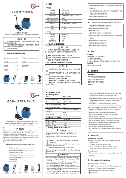
1、包装清单及各部分名称焊 台 (1)烙铁头 (1)抗热垫 (1)电源线........................1 手柄线 (1)烙铁架 (1)使用说明书 (1)● 焊台2、规格功率消耗温度范围温度稳定度烙铁头至接地电阻烙铁头至接地电势外形尺寸重量总重120W/220V200~500℃非使用状态时为±2℃(±3.6℉)2Ω以下2mV以下98(W)X98(D)X118(H)mm1.5Kg2.15kg● 手柄手柄长度 150mm线长 1.3m手柄线重量 75g3、安全及使用注意事项警 告本说明书注意事项区分如下之「警告」「注意」「注记」三者加以表示。
请充分了解其内容后再阅读本文。
●更换部件或装置烙铁头时,应关掉电源,并待烙铁头冷却至室温。
●在没有得到相关负责人的许可下,经验及知识不足者(包括儿童)请勿使用本产品。
●请注意不要让儿童触碰本产品。
●以下注意事项与GD90之事故或故障有关,请务必遵守。
●切勿使用GD90用在焊接以外的工作。
●切勿将GD90泡水或用湿手使用。
●切勿改装本产品。
●更换零件时,使用GUDHEP原厂部件。
●切勿为了弄掉烙铁头上的锡屑而用力敲打。
此举会损伤烙铁头。
●焊接时会冒烟,请做好通风。
●请勿进行其他认为危险行为。
●不使用时将手柄放在焊铁架上。
4、组装A.烙铁架●使用海绵时,先沾水再挤干。
1、将海绵放在烙铁架上。
2、滴入少量的清水,等海绵完全吸收,再将其挤干净。
B.手柄线手柄与焊台之间的连接。
5、 使用方法焊台示意图GD90焊台具有下列控制装置:增加显示幕所示的数值减少显示幕所示的数值确定GD90 USER MANUALThanks for your supporting about our products.Before use please read this manual carefully,If you have any questions, please contact us.NoteThis product is equipped with anti-static and Connected to the ground of part of the soldering iron. Please pay attention to the following precautions:1.Plastics such as handles are conductive plastics, please pay attention when repairing.When replacing or repairing parts, do not damage the insulating material.2.Be sure to use it to grounded.1、Packing List and Name of each part警告:滥用可能导致使用者伤亡或负重伤。
50K单联电位器RK097111020N 选型手册
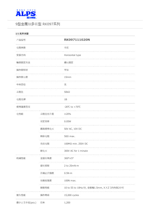
9型⾦属轴多联型 RK097系列1轴⽆开关型产品编号RK097111020N电阻体数单联安装⽅向Horizontal type軸受固定⽅法螺纹固定操作部形状平轴操作部长度15mm中央定位⽆总阻值50kΩ电阻规律1B使⽤温度范围-20℃ to +70℃电性能总阻值允许差±20%额定功率0.05W最⾼使⽤电压50V AC, 10V DC剩余电阻50Ω max.绝缘电阻100MΩ min. 250V DC耐电压300V AC for 1 minute机械性能全旋转⾓度300°±5°旋转扭矩 2 to 25mN·m终端⽌挡强度0.5N·m轴推拉强度100N max.耐振性能10 to 55 to 10Hz/分, 全振幅1.5mm, X.Y.Z 3⽅向各2⼩时耐久性能操作寿命15,000 cycles最⼩订货单位(pcs.)⽇本1,200出⼝2,400照⽚外形图安装孔尺⼨图⾃插⼊侧看端⼦尺⼨轴承尺⼨附加零部件是附加到各产品上的零部件。
包装规格托盘包装数(pcs.)1箱/⽇本1,2001箱/出⼝包装2,400出⼝包装箱尺⼨(mm)375×490×185焊接条件浸焊⽅式的参考举例预热焊接⾯表⾯温度100℃ max.加热时间 2 min. max.浸焊焊接温度260±5℃ max.焊接时间5±1s焊接次数 2 time max.⼿⼯焊接⽅式的参考举例烙铁头温度350℃ max.焊接时间3s max.焊接次数 1 time表⽰本系列共通的注释。
1. 本产品⽬录中产品的颜⾊,与实物的颜⾊有所差异。
2. 附属开关可以选择单内轴型和双内轴型。
3. 请以最⼩订购单位的N(整数)倍来订货。
4. 除了产品⼀览之外,还备有丰富的可适⽤产品规格。
5. 本系列产品也可以⽤于车载。
的使⽤温度范围设定虽然⽐通常的⼤,但是请在使⽤时仔细确认正式的技术规格书。
数字电位器芯片X9511的应用扩展

数字电位器芯片X9511的应用扩展杨善迎莱芜职业技术学院引言数字电位器在我国还是近几年出现的新型器件,该器件一出现,就以其调节准确方便,使用寿命长,受物理环境影响小,性能稳定等特点,而被广大电子工程技术人员所接受。
但数字电位器本身能够承受的电流和电压有限,因而需要扩展,同时在实际应用中,数字电位器的阻值范围及分辨率也需要扩展,本文介绍的扩展方案适用于各种信号的数字电位器。
数字电位器简介数字电位器是可用数字信号控制电位器滑动端位置的新型器件,一般分按钮控制和串行信号控制两种,X9511就是XICOR公司生产的理想按键式数字电位器,它内含31个串联电阻阵列和32个轴头。
轴头位置由两个按键控制,并且可以被存储在一个E2PROM存储器中,以供下一次通电时重新调用,并自动恢复轴头位置,X9511有1kΩ和10kΩ的X9511Z和X9511W两种规格。
X9511内部由计数器、存储器、译码器、模拟开关和电阻阵列等电路组成,其中计数器是5位可逆计数器,可用于对控制信号PU(或PD)进行加(或减)计数,计数器的计数值可以在ASE 的控制下存储非易失性存储器中。
计数器的数值经过32选1译码器译码后可用于控制模拟开关,32个模拟开关相当于电位器的32个轴头,电阻阵列由采用集成电路工艺制作的31个串联一起的电阻构成,电阻两端分别连接模拟开关的一端,而模拟开关的另一端连接在一起构成数字电位器的滑动端(VW),译码器的输出端可控制模拟开关的通断,从而实现滑动轴头位置的变化。
X9511的计数器电路具有以下特点:◆输入端具有内部上拉电阻和消除开关抖动的抗扰电路,当输入脉冲宽度小于40ms时,计数器将其视为干扰信号而不进行计数;◆PU和PD引脚可直接连接一个按钮开关到地,当按钮按下时,在PU或PD端产生一个负脉冲,使计数器进行加1(按PU键)或减1(按PD键)计数;◆能将计数值存储在非易失性存储器E2PROM中长期保存;◆能在上电时自动将E2PROM中的数据恢复到计数器中;◆当计数器计数到最大值“31”时,PU按键失效,而计数到最小值“0”时,PD按键失效,从而避免循环计数,保证电位器调到最大位置时不会跳到零位,或从零位跳到最大位置。
19032中文说明书

1. 1.1 1.2
2.
3.
4. 4.1 4.2 4.3 4.4 4.5
4.5.1 4.5.2 4.5.3
4.6
4.6.1 4.6.2
4.7
4.7.1 4.7.2
4.8
4.8.1 4.8.2 4.8.3
4.9 4.10 4.11 4.12 4.13
5. 5.1 5.2
5.2.1 5.2.2 5.2.3 5.2.4 5.2.5
讀取記憶體................................................................................................................ 4-8 儲存記憶體................................................................................................................ 4-8 刪除記憶體................................................................................................................ 4-8
測試參數 (PROGRAM) 設定 ....................................................................4-10
操作方式.................................................................................................................. 4-10 各項參數設定資料說明.......................................................................................... 4-10
常用元器件封装尺寸大小

封装形式图片国际统一简称LDCCLGALQFPPDIPTO5TO52TO71TO71TO78PGAPlastic PIN GridArray 封装形式图片国际统一简称TSOPThinSmall OUtlinePackageQFPQuadFlat PackagePQFP 100LQFPQuadFlat PackageSOT143SOT220Thin ShrinkQutline PackageuBGAPLCCLQFPLQFP 100LTO8TO92TO93T099EBGA 680LQFP Quad Flat PackageTQFP 100LMicro Ball GridArrayuBGA Micro Ball GridArrayPCDIPZIPZig-Zag Inline PackaSOT223SOT223SOT23SOT23/SOT323 SOT25/SOT353SBGALBGA 160LPBGA 217L Plastic Ball GridArraySBGA 192LTSBGA 680LCLCCSC-705LSDIPSIPSingle Inline Package SOT26/SOT363FBGAFDIPSOJSOP EIAJ TYPE II 14LSSOP 16LSSOPSOJ 32LFlat PackHSOP28SOSmall OutlinePackageCNRCPGA Ceramic Pin OutlinePackageDIPDual Inline PackageDIP-tab DUAL Inline Package with MetalHeatsinkBQFP 132C-BendLeadITO220ITO3PTO220TO247TO264TO3JLCCLCCTO263/TO268SO DIMM Small Outline Dual In-line MemoryCERQUADCeramic QuadFlatCeramicCase LAMINATE CSPT12LChip Scale PackageGullwingleadsSOT343SOT523SOT89SOT89ModuleSOCKET 370 For intel 370 Pin PGA PentiumIII & Celeron CPUSIMM30Single Inline Memory ModuleSIMM72Single Inline Memory ModuleSIMM72Single inline Memory Modulepin PGA pentium 4 CPUSOCKET462/SOCKET A For PGA AMD Athlo & Duron CPUSocket 603FosterLLP 8LaPCI 32bit 5VPeripheralComponent Interconnect PCI 64bit 3.3VPeripheralComponent InterconnectPCMCIATCSP 20L Chip ScalePackageTO252SOCKET7 For intel PentiumPSDIP SLOT1 For intel pentiumII petiumIII & Celeron CPU SLOT A For AMDAthloncpuSNAPTKSNAPTKSNAPZPSOHBGABall Grid ArrayTO18& MMXpentiumCPU一、直插式电阻封装及尺寸直插式电阻封装为AXIAL-xx形式(比如AXIAL-0.3、AXIAL-0.4),后面的xx 代表焊盘中心间距为xx英寸,这一点在网上很多文章都没说清楚,单位为英寸。
alps脉冲电位器

alps脉冲电位器
Alps脉冲电位器是由日本的ALPS Electric(阿尔卑斯电气)
公司生产的一种电位器。
脉冲电位器是一种特殊类型的电位器,它可以通过脉冲信号进行调节。
这种电位器通常用于音量控制器、音频设备和调音台等应用中。
ALPS Electric公司是一家专业生产电子元件的公司,他们生
产的电位器具有很高的品质和可靠性。
Alps脉冲电位器采用
了先进的材料和制造工艺,具有稳定的性能和长寿命。
Alps脉冲电位器通常有多个档位,通过脉冲信号选择不同的
档位来调节电阻值。
这种调节方式可以快速、准确地调节电位器的数值,使其在不同的应用中具有更好的灵活性和精确性。
总之,Alps脉冲电位器是一种高质量的电位器,具有灵活、
精确的调节性能,广泛应用于音频设备和调音台等领域。
艾顿公司产品:2路电压接触器类型AFDD+防炸性防护设备说明书
Protective DevicesArc Fault Detection Device AFDD+,Catalog1.1Protective DevicesArc Fault Detection Device AFDD +, 2-pole• A rc Fault Detection Device acc. to IEC/EN-62606• D etects and quenches arc faults in final circuits• F ully combined with residual current circuit breaker (RCCB) and miniature circuit breaker (MCB)• 2-pole: Both clearances between open contacts are protected• V ariable installation of N either to the left or right• R ated currents from 6 to 40 A • C ontact position indicator red – green • T ripped indication: MCB, RCCB or AFDD • L ED indication for arc faults • P ermanent self-monitoring • O vervoltage and overheat monitoring • G uide for secure terminal connection • 3-position DIN rail clip, permits removal from existing busbar system• C omprehensive range of accessories suitable for subsequent installation • 10 and 30 mA rated residual currents • T ripping characteristics B, C • R ated breaking capacity up to 10 kA • T he -OL types are specifically designed to fullfill the tripping characteristic requirements of I 2 ≤ I z in the Norwegian electrotechnical standard NEK 400-8-823.Descriptionsg064161.2Protective DevicesArc Fault Detection Device AFDD+, 2-poleType F, 10 kA, 2-poleSurge current-proof 3 kA, sensitive to residual pulsating DC, type Fsg0641610OL/0.03AFDD-10/2/B/003-F-OL MB-3001841/4013OL/0.03AFDD-13/2/B/003-F-OL MB-3001851/4015OL/0.03AFDD-15/2/B/003-F-OL MB-3001861/4020OL/0.03AFDD-20/2/B/003-F-OL MB-3001871/4010/0.03AFDD-10/2/B/003-F1872431/4013/0.03AFDD-13/2/B/003-F1872531/4016/0.03AFDD-16/2/B/003-F1872631/4020/0.03AFDD-20/2/B/003-F1872721/4025/0.03AFDD-25/2/B/003-F1872781/40I n/ID n(A)TypeDesignationArticle No.Units perpackage10OL/0.03AFDD-10/2/C/003-F-OL MB-3001791/4013OL/0.03AFDD-13/2/C/003-F-OL MB-3001801/4015OL/0.03AFDD-15/2/C/003-F-OL MB-3001811/4020OL/0.03AFDD-20/2/C/003-F-OL MB-3001821/406/0.03AFDD-6/2/C/003-F MB-3001781/4010/0.03AFDD-10/2/C/003-F1872491/4013/0.03AFDD-13/2/C/003-F1872591/4016/0.03AFDD-16/2/C/003-F1872691/4020/0.03AFDD-20/2/C/003-F1872751/4025/0.03AFDD-25/2/C/003-F1872811/40Characteristic CType F, 6 kA, 2-poleSurge current-proof 3 kA, sensitive to residual pulsating DC, type F32/0.03AFDD-32/2/B/003-F1872841/4040/0.03AFDD-40/2/B/003-F1872901/40Characteristic B32/0.03AFDD-32/2/C/003-F1872871/4040/0.03AFDD-40/2/C/003-F1872931/40Characteristic Csg06416Characteristic B1.3Protective DevicesArc Fault Detection Device AFDD+, 2-poleType G/A, 10 kA, 2-poleSurge current-proof 3 kA, sensitive to residual pulsating DC, type G/Asg0641610/0.01AFDD-10/2/B/001-G/A MB-3001941/4013/0.01AFDD-13/2/B/001-G/A MB-3001951/4016/0.01AFDD-16/2/B/001-G/A MB-3001961/4010/0.03AFDD-10/2/B/003-G/A MB-3001621/4013/0.03AFDD-13/2/B/003-G/A MB-3001651/4016/0.03AFDD-16/2/B/003-G/A MB-3001681/4020/0.03AFDD-20/2/B/003-G/A MB-3001701/4025/0.03AFDD-25/2/B/003-G/A MB-3001731/40I n/ID n(A)TypeDesignationArticle No.Units perpackage Characteristic B6/0.01AFDD-6/2/C/001-G/A MB-3001881/4010/0.01AFDD-10/2/C/001-G/A MB-3001891/4013/0.01AFDD-13/2/C/001-G/A MB-3001911/4016/0.01AFDD-16/2/C/001-G/A MB-3001921/406/0.03AFDD-6/2/C/003-G/A MB-3001381/4010/0.03AFDD-10/2/C/003-G/A MB-3001471/4013/0.03AFDD-13/2/C/003-G/A MB-3001491/4016/0.03AFDD-16/2/C/003-G/A MB-3001521/4020/0.03AFDD-20/2/C/003-G/A MB-3001531/4025/0.03AFDD-25/2/C/003-G/A MB-3001551/40Characteristic CType G/A, 6 kA, 2-poleSurge current-proof 3 kA, sensitive to residual pulsating DC, type G/A32/0.03AFDD-32/2/B/003-G/A MB-3001741/4040/0.03AFDD-40/2/B/003-G/A MB-3002221/40Characteristic B32/0.03AFDD-32/2/C/003-G/A MB-3001581/4040/0.03AFDD-40/2/C/003-G/A MB-3001591/40Characteristic Csg064161.4Protective DevicesArc Fault Detection Device AFDD+, 2-poleType A, 10 kA, 2-poleNon-delayed, sensitive to residual pulsating DC, type Asg0641610/0.01AFDD-10/2/B/001-A 187165 1/4010OL/0.03AFDD-10/2/B/003-A-OL MB-3002171/4013OL/0.03AFDD-13/2/B/003-A-OL MB-3002211/4013/0.01AFDD-13/2/B/001-A 187177 1/4016/0.01AFDD-16/2/B/001-A 187201 1/4010/0.03AFDD-10/2/B/003-A 187168 1/4013/0.03AFDD-13/2/B/003-A 187180 1/4015OL/0.03AFDD-15/2/B/003-A-OL 187192 1/4016/0.03AFDD-16/2/B/003-A 187204 1/4020OL/0.03AFDD-20/2/B/003-A-OL 187213 1/4020/0.03AFDD-20/2/B/003-A 187219 1/4025/0.03AFDD-25/2/B/003-A 187225 1/40I n/ID n(A)TypeDesignationArticle No.Units perpackage Characteristic B6/0.01AFDD-6/2/C/001-A MB-3002061/4010/0.01AFDD-10/2/C/001-A 187171 1/4010OL/0.03AFDD-10/2/C/003-A-OL MB-3002151/4013OL/0.03AFDD-13/2/C/003-A-OL MB-3002161/4013/0.01AFDD-13/2/C/001-A 187183 1/4016/0.01AFDD-16/2/C/001-A 187207 1/406/0.03AFDD-6/2/C/003-A MB-3001991/4010/0.03AFDD-10/2/C/003-A 187174 1/4013/0.03AFDD-13/2/C/003-A 187186 1/4015OL/0.03AFDD-15/2/C/003-A-OL 187198 1/4016/0.03AFDD-16/2/C/003-A 187210 1/4020OL/0.03AFDD-20/2/C/003-A-OL 187216 1/4020/0.03AFDD-20/2/C/003-A 187222 1/4025/0.03AFDD-25/2/C/003-A 187228 1/40Characteristic CType A, 6 kA, 2-poleNon-delayed, sensitive to residual pulsating DC, type A32/0.03AFDD-32/2/B/003-A 187231 1/4040/0.03AFDD-40/2/B/003-A 187237 1/40Characteristic B32/0.03AFDD-32/2/C/003-A 187234 1/4040/0.03AFDD-40/2/C/003-A 187240 1/40Characteristic Csg064161.5Protective DevicesArc Fault Detection Device AFDD+, 2-poleType AC, 10 kA, 2-poleNon-delayed, alternating-current-sensitive, type ACsg0641610/0.01AFDD-10/2/B/001 187164 1/4013/0.01AFDD-13/2/B/001 187176 1/4016/0.01AFDD-16/2/B/001 187200 1/4010/0.03AFDD-10/2/B/003 187167 1/4013/0.03AFDD-13/2/B/003 187179 1/4016/0.03AFDD-16/2/B/003 187203 1/4020/0.03AFDD-20/2/B/003 187218 1/4025/0.03AFDD-25/2/B/003 187224 1/40I n/ID n(A)TypeDesignationArticle No.Units perpackage Characteristic B6/0.01AFDD-6/2/C/001MB-3002051/4010/0.01AFDD-10/2/C/001 187170 1/4013/0.01AFDD-13/2/C/001 187182 1/4016/0.01AFDD-16/2/C/001 187206 1/406/0.03AFDD-6/2/C/003MB-3001971/4010/0.03AFDD-10/2/C/003 187173 1/4013/0.03AFDD-13/2/C/003 187185 1/4016/0.03AFDD-16/2/C/003 187209 1/4020/0.03AFDD-20/2/C/003 187221 1/4025/0.03AFDD-25/2/C/003 187227 1/40Characteristic CType AC, 6 kA, 2-poleNon-delayed, alternating-current-sensitive, type AC32/0.03AFDD-32/2/B/003 187230 1/4040/0.03AFDD-40/2/B/003 187236 1/40Characteristic B32/0.03AFDD-32/2/C/003 187233 1/4040/0.03AFDD-40/2/C/003 187239 1/40Characteristic Csg064161.6Protective DevicesArc Fault Detection Device AFDD+, 2-pole - T echnical DataSpecifications | Arc Fault Detection Device AFDD+, 2-poleDescription• Arc Fault Detection Device acc. to IEC/EN-62606• L ine-voltage-independent RCBO (combined switch) acc. to IEC/EN 61009• 2-pole: Both clearances between open contacts are protected• V ariable installation of N either to the left or the right• T ripped indication: MCB, RCCB or AFDD• L ED indication for arc faults• Compatible with standard busbar• T win-purpose terminal (lift/open-mouthed) above and below• B usbar positioning optionally above or below• F ree terminal space despite installed busbar• Guide for secure terminal connection• Switching toggle (MCB component) in colour designating the rated current • Contact position indicator red - green• Comprehensive range of accessories can be mounted subsequently• T he test key “T” must be pressed every 6 months. The system operator must be informed of this obligation and their responsibility in a way that can be proven (self-adhesive RCD-label enclosed). The test interval of 6 months is valid for residential and similar applications. Under all other conditions (e.g. damp or dusty environments), it’s recommended to test in shorter intervals (e.g. monthly).• P ressing the test key “T” serves the only purpose of function testing the residual current device (RCD). This test does not perform an earthing resist-ance measurement (R E), nor does it render the check of the earth conductor condition redundant, which means both tests must additionally be performed separately.• T he cable length (one-way) from the AFDD+ to the socket outlet should not exceed 70 m. This guarantees that arc faults can be detected reliably.• T ype -A: Protects against special forms of residual pulsating DC which have not been smoothed•T ype-F: Sensitive to pulsating DC residual current and detection of multi-frequency residual currents up to 1 kHz-Increased protection due to the detection of mixed frequencies-Higher load rating with DC residual currents up to 10 mA-Reduction of nuisance tripping thanks to time delayed tripping and increased current withstand capability of 3 kARecommended for washing machines, dish washers, or motor applications with single-phase drives.•T ype-G/A: Additionally protects against special forms of residual pulsating DC which have not been smoothed•T ype-G: High reliability against unwanted tripping. Suitable for any circuit where personal injury or damage to property may occur in case of unwanted tripping. Additionally protects against special forms of residual pulsating DC which have not been smoothed.•O L types:Specifically designed to fulfill the tripping characteristic requirements of I2≤ I z in the Norwegian electrotechnical standardNEK 400-8-823. 10:28Error memory:The AFDD+ saves the last tripping reason/cause. If the device is in the open position (turned off), press and hold the test button “T” and simultaneously turn on the device. This causes the in-built LED to flash in a sequence that will reveal the tripping cause.Accessories:Auxiliary switch for subsequent installation ZP-IHK286052Auxiliary switch ZP-NHK248437ZP-WHK286053Shunt trip release ZP-ASA/..248438, 248439 Busbars EVG-2PHAS/4AFDD; ZV-SS; ZV-L1/N; ZV-L2/L3; ZV-ADP; ZV-AEK1.7Protective DevicesArc Fault Detection Device AFDD+, 2-pole - T echnical DataTechnical DataAFDD+ElectricalDesign according toRelevant effective certification marks as printed onto the device IEC/EN 62606IEC/EN 61009IEC/EN 62423Type G acc. to ÖVE E 8601Line voltage-independent tripping instantaneous surge current proof 250 A (8/20 µs)surge current proof 3 kA (F, -F-OL, -G/A, -G/A-OL) (8/20 µs) Rated voltage U n240 V AC; 50 HzOperational voltage range180-264 VSelf-consumption< 0.8 WRated residual operating current ID n 10, 30 mARated residual non-operating current ID no 0.5 ID nSensitivity AC and pulsating DC, Type FSelectivity class3Rated breaking capacityAFDD 6-25 A10 kAAFDD 32-40 A 6 kARated current 6 - 40 ARated insulation voltage U i440 VRated impulse withstand voltage U imp 4 kV (1.2/50 µs)Rated residual making and breaking capacity ID mEN 61009 3 kAIEC 610096-16 A: 3 kA20-40 A: 500 AArc fault tripping times after load current (acc. to IEC/EN 62606)Load current (A)Tripping time (s)2,5<15<0.510<0.2516<0.1532<0.1240<0.12Characteristic B, C, B(-OL), C(-OL)Maximum back-up fuse (short-circuit)100 A gL (>10 kA)Enduranceelectrical components> 4,000 switching operationsmechanical components> 20,000 switching operationsMechanicalFrame size45 mmDevice height80 mmDevice width54 mm (3 MU)Mounting 3-position DIN rail clip, permits removal from existing busbar system Degree of protection, switch IP20Degree of protection, built-in IP40Upper and lower terminals open-mouthed/lift terminalsTerminal protection finger and hand touch safe, EN 50274Terminal cross section (capacity) 1 - 25 mm2Busbar thickness 0.8 - 2 mmOperating temperature -25° C to +40° CStorage and transport temperature-35° C to +60° CResistance to climatic conditions according to IEC/EN 610091.8Protective DevicesArc Fault Detection Device AFDD +, 2-pole - T echnical DataConnection diagramDimensions (mm)Tripping Characteristic AFDD +, Characteristics B and CDeclaration AFDD reason for trippingAfter switching on the AFDD is initially a test LED (LED sequence red-yellow-green -> continuous green).Any previous arc tripping reasons are shown only one time after switching on again.Green, no arcing as tripping reason 1x yellow, serial arc2x yellow, serial arc of a dimmed load 3x yellow, parallel arc4x yellow, over voltage (about 270V) AFDD tripped for self protection5x yellow, overtemperature in the device (about >115°C) AFDD tripped for self protection6x yellow, device error, please check device by an expertThe last AFDD error can be reshown by pressing the test key while the device is switched on.1.9Protective DevicesArc Fault Detection Device AFDD +, 2-pole - T echnical DataShort-circuit Selectivity AFDD + 10-20 A towards Neozed 1) / Diazed 2) / NH003)Short-circuit currents in kA, rated currents of fuses in A Short-circuit selectivity AFDD + towards Neozed 1)Darker areas: no selectivity 1) S IEMENS Type 5SE2; Size: D01, D02, D03; Operating class gG; Rated voltage: AC 400 V/DC 250 V 2) S IEMENS Type 5SB2, 5SB4, 5SC2; Size: DII, DIII, DIV; Operating class gG; Rated voltage: AC 500 V/DC 500 V 3) S IEMENS Type 3NA3 8, 3NA6 8, 3NA7 8; Size: 000, 00; Operating class gG; Rated voltage: AC 500 V/DC 250 VShort-circuit selectivity AFDD + towards Diazed 2)Short-circuit selectivity AFDD + towards NH00 3)Short-circuit Selectivity AFDD + 25-40 A towards Neozed 1) / Diazed 2) / NH003)Short-circuit currents in kA, rated currents of fuses in A Short-circuit selectivity AFDD + towards Neozed 1)Short-circuit selectivity AFDD + towards Diazed 1)Darker areas: no selectivity 1) S IEMENS Type 5SE2; Size: D01, D02, D03; Operating class gG; Rated voltage: AC 400 V/DC 250 V 2) S IEMENS Type 5SB2, 5SB4, 5SC2; Size: DII, DIII, DIV; Operating class gG; Rated voltage: AC 500 V/DC 500 V 3) S IEMENS Type 3NA3 8, 3NA6 8, 3NA7 8; Size: 000, 00; Operating class gG; Rated voltage: AC 500 V/DC 250 VShort-circuit selectivity AFDD + towards NH003)AFDD +Neozed 1)I n [A]162025323540506380100B10/B10-OL <0.50.50.92 2.3 3.78101010<0.50.50.8 1.7 1.936101010AFDD +Diazed 2)I n [A]1620253235506380100B10/B10-OL <0.50.50.9 1.8 2.9 5.6101010<0.50.50.8 1.5 2.4 4.5101010AFDD +NH00 3)I n [A]162025323540506380100125160B10/B10-OL <0.5<0.50.8 1.5 2.3 3.2 5.79.110101010AFDD +Neozed 1)AFDD +Diazed 2)AFDD +NH00 3)1.1010EATON CORPORATION CA019040ENProtective DevicesArc Fault Detection Device AFDD +, 2-pole - T echnical DataLet-through Energy AFDD +Let-through Energy AFDD +, Characteristic B, 2-pole, 10-20 ALet-through Energy AFDD +, Characteristic C, 2-pole, 6-20 AProspective Short-circuit Current I cc [A]L e t -t h r o u g h E n e r g y I 2t [A 2 s e c]L e t -t h r o u g h E n e r g y I 2t [A 2 s e c ]Prospective Short-circuit Current I cc [A]Let-through Energy AFDD +, Characteristic B, 2-pole, 25-40 ALet-through Energy AFDD +, Characteristic C, 2-pole, 25-40 AProspective Short-circuit Current I cc[A]L e t -t h r o u g h E n e r g y I 2t [A 2 s e c ]Prospective Short-circuit Current I cc [A]EatonEMEA Headquarters Route de la Longeraie 71110 Morges, Switzerland © 2021 EatonAll Rights ReservedPublication No. CA019040EN Article number 302723-MK November 20229010238177932Eaton Industries (Austria) GmbH Scheydgasse 421210 Vienna AustriaFollow us on social media to get the latest product and support information.Eaton is a registered trademark.All other trademarks are property of their respective owners.To contact us please visit https:///contacts For technical questions please contact your local Eaton team.Changes to the products, to the information contained in thisdocument, and to prices are reserved; as are errors and omissions.Only order confirmations and technical documentation by Eaton is binding. Photos and pictures also do not warrant a specific layout or functionality. Their use in whatever form is subject to prior approval by Eaton. The same applies to trademarks (especially Eaton, Moeller,and Cutler-Hammer). The Terms and Conditions of Eaton apply, as referenced on Eaton Internet pages and Eaton order confirmations.Eaton’s electrical business is a global leader with deep regionalapplication expertise in power distribution and circuit protection; power quality, backup power and energy storage; control and automation; life safety and security; structural solutions; and harsh and hazardous environment solutions. Through end-to-end services, channel and an integrated digital platform & insights Eaton is powering what matters across industries and around the world, helping customers solve their most critical electrical power management challenges.For more information, visit .。
ALPS 16型电位器
4 12.5 55
4.5 ø6
ø3
R2 R1
M7ʷ0.75 2
C1
12 15
3
1
Shaft shown in full CCW position
Mounting surface
6-ø1.2 holes
12.1
15
5
8
7.5 1.5 0.3
5
3.8
Mounting
surface
0.7 ø6 ø3
4 12.5
367
电阻规律sP.368, 470 附加零部件sP.379
16型金属轴型电位器
关于推荐产品以外的订货
若订购产品一览里没有记载的产品,请参阅下例进行指定。 订货时的记入举例
RK1 6 3 1 1 1 0 F 2 0 C0 B1 0 3 P
产品型号 记号 111 121 12A
操作部形状 记号 F S K
100kЊʽR
100dB min.
绝缘电阻
100MΩ min, 500V DC
耐电压
500V AC for 1minute
机 旋转止挡强度(N·m)
械 性
轴推拉强度
能
耐振性能
0.9N·m
100MΩ min. 250V DC
100MΩ min. 500V DC
300V AC for 1minute
500V AC for 1minute
RK1631110TNP 2
配线
齿形
15
Horizontal
接线
type
平轴
20
2联
音质用
2联 音量用
齿形
15
配线
20
EATON GD GWF 480V 单 双 三极电路保护器及切换器安装指南说明书
ContentsDescription Pa g e Introduction . . . . . . . . . . . . . . . . . . . . . . . . . . . . . .2Installation . . . . . . . . . . . . . . . . . . . . . . . . . . . . . . .2Manual Operation . . . . . . . . . . . . . . . . . . . . . . . . .5Inspection and Field Testing . . . . . . . . . . . . . . . . .5Installation Instructions for GD/GWF MoldedCase Circuit Breakers and Switches2Instruction Leaflet IL 29C102GEffective June 2016Installation Instructions for GD/GWF MoldedCase Circuit Breakers and SwitchesEATON Figure 1-1 GWF 480V, 1, 2, 3 Pole Circuit Breakers; 2 and 3 Pole Molded Case Switches and GD 480V 2 and 3 Pole Circuit Breakers; GD 3 Pole Molded Case SwitchDO NOT ATTEMPT TO INSTALL OR PERFORMMAINTENANCE ON EQUIPMENT WHILE IT IS ENER-GIZED. SEVERE PERSONAL INJURY, DEATH, OR SUBSTANTIAL PROPERTY DAMAGE CAN RESULT FROM CONTACT WITH ENERGIZED EQUIPMENT.ALWAYS VERIFY THAT NO VOLTAGE IS PRESENT BEFORE PROCEEDING WITH THE TASK, ANDALWAYS FOLLOW GENERALLY ACCEPTED SAFE-TY PROCEDURES.EATON IS NOT LIABLE FOR THE MISAP PLICATION OR MISINSTALLATION OF ITS PROD UCTS.The user is cautioned to observe all recommendations,warnings, and cautions relating to the safety of person-nel and equipment as well as all general and local health and safety laws, codes, and procedures. The recommendations and information contained herein are based on Eaton experience and judge ment, but should not be considered to be all-inclusive or covering every application or circumstance which may arise.If any questions arise, contact Eaton for further inform-ation or instructions.1. INTRODUCTIONGD & GWF circuit breakers (Figure 1-1)are thermal- magnetic devices.Some styles of circuit breakers have steel terminals as opposed to aluminum terminals. Three methods of mounting these circuit breakers are available: hardware, DIN rail, or basemounting plate.The following accessories are available for use with GD/GWF circuit breakers:*Auxiliary Switch*Alarm (Signal)/Lockout switch *Shunt Trip*Undervoltage Release Mechanism *Lock Dog (S# 1294C01H01)*Padlockable Handle (S# 1223C77G03, for 1 pole only)2. INSTALLATIONThe installation procedure consists of inspecting and mounting the circuit breaker, connecting and torquing terminations. To install the circuit breaker, perform the following steps.Note:GD/GWF circuit breakers are factory sealed. Underwriters Laboratories, Inc. Standard requires that internal accessories be installed at the factory.Figure 2-1 Circuit Breaker Mounting Bolt Drilling Plan3Instruction Leaflet IL 29C102GEffective June 2016Installation Instructions for GD/GWF Molded Case Circuit Breakers and SwitchesEATON Where local codes and standards permit and UL listing is not required, internal accessories can be field installed. Accessory installation should be done before the circuit breaker is mounted and connected. Mounting hardware is supplied with breaker.2-1.Make sure that the circuit breaker is suitable for the intended installation by comparing nameplate data with system requirements. Inspect the circuit breaker for com-pleteness, and check for damage before mounting.BEFORE MOUNTING THE CIRCUIT BREAKER IN AN ELECTRICAL SYSTEM, MAKE SURE THE CIRCUIT BREAKER IS SWITCHED TO THE OFF POSITION AND THAT THERE IS NO VOLTAGE PRESENT WHERE WORK IS TO BE PERFORMED. SPECIAL ATTENTION SHOULD BE PAID TO REVERSE FEED APPLICATIONS TO ENSURE NO VOLTAGE IS PRE-SENT. THE VOLTAGE IN ENERGIZED EQUIPMENT CAN CAUSE SEVERE PERSONAL INJURY OR DEATH.2-2.To mount the circuit breaker, perform the followingsteps:Note:If circuit breaker includes factory installed internal accessories, make sure accessory wiring can be reached when the circuit breaker is mounted. a. Individual Mounting PanelsPredrill panel and tap holes using bolt drilling plan (Figure 2-1). Install circuit breaker using mountingscrews and washers. Tighten screws firmly, but do not exceed 15 inch pounds (1.69 N.m.).b. DIN Rail MountingAdapter kit (S# 1225C79G01 for 1 and 2 pole breakers and S# 1225C79G02 for 3 pole breakers) suitable for use with standard 35 millimeter DIN rail (such as 35mm x 7.5 or 35mm x 15 per DIN EN50022), should be pre-assembled to the rear of the circuit breaker as required by snapping adapter onto DIN rail.c. Base Mounting PlateInstall base mounting plate (S# 207B513G01 - suitable for mounting six 1-pole, three 2-pole, and two 3-pole breakers) with hardware provided. A recess is providedin the line and load-end of the circuit breaker for mount-ing to base mounting plate. Clip circuit breaker into retaining clips load-end first. d. Deadfront CoverFigure 2-3 Line End Terminal BarrierCircuit Breaker View Cut Away to Show Line End Terminal BarrierLine EndTerminal BarrierCut out mounting panel cover to correct escutcheondimensions (Figure 2-2).WHEN ALUMINUM CONDUCTORS ARE USED, THE APPLICATION OF A SUITABLE JOINT COMPOUND IS RECOMMENDED TO REDUCE THE POSSIBILITY OF TERMINAL OVERHEATING. TERMINAL OVER-HEATING CAN CAUSE NUISANCE TRIPPING AND DAMAGE TO THE CIRCUIT BREAKER.2-3 After mounting the circuit breaker, line and load ter-minals and accessory leads should be connected. (See accessory lead identification on side of circuit breaker).2-4 The line end terminal barriers of GD circuit break-ers and molded case switches bend when a screwdriv-er is inserted to tighten line end terminals. (See Figure 2-3)4Instruction Leaflet IL 29C102GEffective June 2016Installation Instructions for GD/GWF MoldedCase Circuit Breakers and SwitchesEATON Figure 2-2 Circuit Breaker Escutcheon DimensionOTable 2-4 GWF Terminal Torque ValuesWindow to Display White StripIndicating TRIPPED ConditionFigure 3-1 Circuit Breaker Manual Controls5Instruction Leaflet IL 29C102GEffective June 2016Installation Instructions for GD/GWF Molded Case Circuit Breakers and SwitchesEATON MAKE SURE THAT CLEANING AGENTS OR SOL-VENTS USED TO CLEAN THE CIRCUIT BREAKER ARE SUITABLE FOR THE JOB. SOME COMMER-CIAL CLEANING AGENTS WILL DAMAGE THE NAMEPLATES OR MOLDED PARTS.4-1Remove dust, dirt, soot, grease, or moisture from the surface of the circuit breaker using a lint-free dry cloth, brush, or vacuum cleaner. Do not blow debris into circuit breaker. If contamination is found, look for the source and eliminate the problem.4-2Switch circuit to ON and OFF several times to be sure that the mechanical linkages are free and do not bind. If mechanical linkages are not free and are bind-ing, replace circuit breaker.4-3Check base, cover, and operating handle for cracks,chipping, and discoloration. Circuit breakers should be replaced if cracks or severe discoloration is found. 4-4Check terminals and connectors for looseness or signs of overheating. Overheating will show as discol-oration, melting, or blistering of conductor insulation, or as pitting or melting of conductor surfaces due to arcing.If there is no evidence of overheating or looseness, do not disturb or tighten the connections. If there is evi-dence of overheating, terminations should be cleaned or replaced. Before reenergizing the circuit breaker, all ter-minations and cable should be refurbished to the condi-tion when originally installed.2-5After the circuit breaker is installed, check all mount-ing hardware and terminal connecting hardware for cor-rect torque loading. Torque values for line/load terminals are given in Tables 2-1,2-2,2-3and 2-4and on the circuit breaker nameplate.3.Manual OperationManual operation of the circuit breaker is controlled by the circuit breaker handle. There are two positionsshown on the handle to indicate when the circuit breaker is ON or OFF, also the tripped position is shown by a white strip. (See Figure 3-1).Circuit Breaker ResetAfter an automatic trip operation, the circuit breaker is reset by moving the circuit breaker handle to the OFF position.Note:In the event of a thermal trip, the circuit breaker cannot be reset until the thermal element cools.4.Inspection and Field TestingMolded case circuit breakers are designed to provideyears of almost maintenance-free operation. The follow-ing procedure describes how to inspect and test a circuit breaker in service.InspectionCircuit breakers in service should be inspected periodi-cally. The inspection should include the following checks.4-5Check circuit breaker mounting hardware, tighten if necessary.4-6Check area where circuit breaker is installed for any safety hazards, including personal safety and fire haz-ards. Exposure to certain types of chemicals can cause deterioration of electrical connections.Field TestingAny field testing should be done in accordance with NEMA Standards Publication AB4-Latest Version.BEFORE INSPECTING THE CIRCUIT BREAKER IN AN ELECTRICAL SYSTEM, MAKE SURE THE CIR-CUIT BREAKER IS SWITCHED TO THE OFF POSI-TION AND THAT THERE IS NO VOLTAGE PRESENT WHERE WORK IS TO BE PERFORMED. SPECIAL ATTENTION SHOULD BE PAID TO REVERSE FEED APPLICATIONS TO ENSURE NO VOLTAGE IS PRE-SENT. THE VOLTAGES IN ENERGIZED EQUIPMENT CAN CAUSE SEVERE PERSONAL INJURY ORDEATH.6Instruction Leaflet IL 29C102GEffective June 2016Installation Instructions for GD/GWF MoldedCase Circuit Breakers and SwitchesEATON NOTES:7Instruction Leaflet IL 29C102GEffective June 2016Installation Instructions for GD/GWF Molded Case Circuit Breakers and SwitchesEATON NOTES:Instruction Leaflet IL 29C102G Effective June 2016Installation Instructions for GD/GWF Molded Case Circuit Breakers and SwitchesEatonElectrical Sector1000 Eaton Boulevard Cleveland, OH 44122United States877-ETN-CARE (877-386-2273) © 2016 EatonAll Rights ReservedPrinted in USAPublication No. IL 29C102G / TBG000478 Part No. 8790C98H07June 2016Eaton is a registered trademark.All other trademarks are property of their respective owners.The instructions for installation, testing, maintenance, or repair herein are provided for the use of the product in general commercial applications and may not be appropriate for use in nuclear applica-tions . Additional instructions may be available upon specific request to replace, amend, or supplement these instructions to qualify them for use with the product in safety-related applications in a nuclear facility .The information, recommendations, descriptions, and safety nota-tions in this document are based on Eaton’s experience and judg-ment with respect to Retrofitting of Power Breakers . This instruction-al literature is published solely for information purposes and should not be considered all-inclusive . If further information is required, you should consult an authorized Eaton sales representative .The sale of the product shown in this literature is subject to the terms and conditions outlined in appropriate Eaton selling policies or other contractual agreement between the parties . This literature is not intended to and does not enlarge or add to any such contract . The sole source governing the rights and remedies of any purchaser of this equipment is the contract between the purchaser and Eaton . NO WARRANTIES, EXPRESSED OR IMPLIED, INCLUDING WARRANTIES OF FITNESS FOR A PARTICULAR PURPOSE OR MERCHANTABILITY, OR WARRANTIES ARISING FROM COURSE OF DEALING OR USAGE OF TRADE, ARE MADE REGARDING THE INFORMATION, RECOMMENDATIONS, AND DESCRIPTIONS CONTAINED HEREIN. In no event will Eaton be responsible to the purchaser or user in contract, in tort (including negligence), strict liability or otherwise for any special, indirect, incidental or conse-quential damage or loss whatsoever, including but not limited to damage or loss of use of equipment, plant or power system, costof capital, loss of power, additional expenses in the use of existing power facilities, or claims against the purchaser or user by its cus-tomers resulting from the use of the information, recommendations and description contained herein .。
人民电器 RDA3系列金属按钮开关 产品说明书
RDA3系列金属按钮开关选型指南表1举例:订购,螺钉式,16孔径的金属按钮,100个应写为:RDA3-S 100个不锈钢白色平钮自复按钮一常开黄铜镀镍红色带单点灯高头自复钮按钮一常开一常闭材质,, -A11L-16,订购材质,,DC24V ,,焊接式,22孔径的金属按钮,100个 应写为:RDA3-H-W1D453-22,100个符合标准应用范围RDA3金属按钮开关适用于直流电压36V ,额定工作电流不大于2A 的控制电路中,作为控制电路通断、工作信号转换、电气连锁之用。
触头有快动型和慢动型两种。
额定工作一般结构与工作原理主要由按钮头部分、基座和触头部分组成,这三部分采用铆压组合,通过变换钮头可派生出不同型式的品种。
变换触头座的种类,组成一常开或一常开一常闭两种规格。
按钮的结构可分为按压式、带灯式、自锁式、紧急式、旋钮式、钥匙式。
钥匙式和旋钮式还可以分为二位或三位。
二位式式一个位置常开触头接通,另一个位置常闭触头接通;而三位置有中间位置0,在此位置常开或常闭触头均断开。
可得到1对或2对触头,193外形图及尺寸平钮-选型规则螺钉式焊接式螺钉式焊接式举例:订购不锈钢,白色平钮自复按钮,一常开,螺钉式,16孔径的金属按钮 100个 应写为:RDA3-S-A11L 16 100个订购黄铜镀镍,红色平钮自锁按钮,一常闭一常闭,焊接式,22孔径的金属按钮 100个 应写为:RDA3-H-AZ4522 100个--194RDA3系列金属按钮开关外形图及尺寸球形钮-选型规则螺钉式焊接式螺钉式焊接式举例:订购不锈钢,白色球形钮自复按钮,一常开,螺钉式,16孔径的金属按钮 100个 应写为:RDA3-S-B11L 16 100个订购黄铜镀镍,红色球形钮自锁按钮,一常开一常闭,焊接式,19孔径的金属按钮 100个 应写为:RDA3-H-BZ4519 100个--195外形图及尺寸高头平钮-选型规则螺钉式焊接式螺钉式焊接式举例:订购不锈钢,白色高头平钮自复按钮,一常开,螺钉式,16孔径的金属按钮 100个 应写为:RDA3-S-GA11L16 100个订购黄铜镀镍,红色高头平钮自锁按钮,一常开一常闭,焊接式,19孔径的金属按钮 100个 应写为:RDA3-H-GAZ4519 100个--196RDA3系列金属按钮开关外形图及尺寸蘑菇钮-选型规则焊接式蘑菇钮自复、自锁举例:订购不锈钢,白色蘑菇钮自复按钮,一常开一常闭,焊接式,19孔径的金属按钮 100个 应写为:RDA3-S-C1519 100个 订购黄铜镀镍,红色蘑菇钮自锁按钮,一常开一常闭,焊接式,22孔径的金属按钮 100个 应写为:RDA3-H-T4522 100个--197外形图及尺寸急停钮-选型规则焊接式急停钮举例:订购不锈钢,红色急停钮按钮,一常开一常闭,焊接式,19孔径的金属按钮 100个 应写为:RDA3-S-S519 100个订购黄铜镀镍,红色急停钮按钮,一常开一常闭,焊接式,22孔径的金属按钮 100个 应写为:RDA3-H-S522 100个--198RDA3系列金属按钮开关外形图及尺寸带灯高钮-选型规则焊接式带单点灯带环形灯举例:订购不锈钢,白色带单点灯高头自复钮按钮,DC12V ,一常开,焊接式,16孔径的金属按钮 100个 应写为:RDA3-S-W1D11216 100个订购黄铜镀镍,红色带单点灯高头自锁钮按钮,DC24V ,一常开一常闭,焊接式,19孔径的金属按钮 100个 应写为:RDA3-H-W1DZ45319 100个--199外形图及尺寸带灯球形钮-选型规则焊接式带环形灯举例:订购不锈钢,白色带环形灯球形自复钮按钮,DC12V,一常开,焊接式,16孔径的金属按钮 100个 应写为:RDA3-S-W2E112-16 100个订购黄铜镀镍,红色带环形灯球形自复钮按钮,DC24V,一常开一常闭,焊接式,22孔径的金属按钮 100个 应写为:RDA3-H-W2EZ453-19 100个200RDA3系列金属按钮开关外形图及尺寸带灯平钮-选型规则螺钉式焊接式带环形灯带单点灯举例:订购不锈钢,白色带单点灯平面自复钮按钮,DC12V ,一常开,螺钉式,16孔径的金属按钮 100个 应写为:RDA3-S-W3D112L-16 100个订购黄铜镀镍,红色带单点灯平面自锁钮按钮,DC24V ,一常开一常闭,焊接式,22孔径的金属按钮 100个 应写为:RDA3-H-W3DZ453-22 100个201外形图及尺寸旋钮-选型规则焊接式举例:订购不锈钢,旋钮二位置锁定按钮,一常开一常闭,焊接式,19孔径的金属按钮 100个 应写为:RDA3-S-D25-19 100个订购黄铜镀镍,旋钮三位置锁定按钮,一常开一常闭,焊接式,22孔径的金属按钮 100个 应写为:RDA3-H-D35-22 100个旋钮202RDA3系列金属按钮开关外形图及尺寸钥匙钮-选型规则焊接式举例:订购不锈钢,钥匙钮二位置锁定按钮,一常开一常闭,焊接式,19孔径的金属按钮 100个 应写为:RDA3-S-Y25-19 100个 订购黄铜镀镍,钥匙钮三位置锁定按钮,一常开一常闭,焊接式,22孔径的金属按钮 100个 应写为:RDA3-H-Y35-22 100个钥匙钮203。