
天行者 Skywakler X5 安装说明书
Skywalker X-5 Fly wing for FPV
Welcome to buy X-5 fly wing, this is a small sized FPV aircraft, but it has enough lift area to carry DC or gopro. It is suitable for cruising at a speed of 60KM/H. It also has a relatively spacious cabin and is convenient to carry around. The installation is very simple. Look at its accessories and installation instructions below .
Parts in the accessories bag: 1 glue , 2 steel tie rods, 2 extension cords , 2 rudder horns and quick connector. And 4 fixed screws for motor and 2 for hatch cover.
First disconnect the winglets
Spread the glue evenly over the winglets and fuselage and wait for five minutes, then adhere the winglets to the fuselage.
Installation of motor: here for 2212 ~ 2215 KV 1600~1900 outer rotor brushless motor, generally it is high speed flight, so we need to adjust the thrust line with two gaskets.
Spread the glue evenly between the motor base and the layer, wait until it is non-sticky, they can be pressed, as for binding benchmark, the bottom edge shall prevail.
The angle is like this after binding
Glue the servo and rudder horn, power on the receiver and make servo stop in the mid-position, and then lock the regulator. After that cut the aileron. Here are advices for players who are new to this fly wing : aileron deflection angle ,which is -20/+20 degrees, is more appropriate. Increase the rudder quantity as you adapt to this.
Spray paint on the hatch cover
Cut some CCD briquette in front of hatch
Gluing on the fuselage
Gluing the antenna base of the data radio
Try whether CCD is suitable for installation
Basically completed
It is looks like this after attaching stickers
When you use a wide-angle lens, you need to cut the front part into some bevels, so as not to keep out line of sight.
Data radio or other devices can be installed above the engine cover, install battery in the forecabin, which is suitable for 2200ma4S batteries. Midbin is fit for placing DC or goupro toward the ground, the rear cabin for OSD and etc. Please use a cable to extend the video transmitter antenna to the far-end of the wing, which can avoid the interference of GPS module's placement on the front inner side of the engine cover. These are our suggestions, you can install the equipment according to own hobby.。
好盈天行者说明书
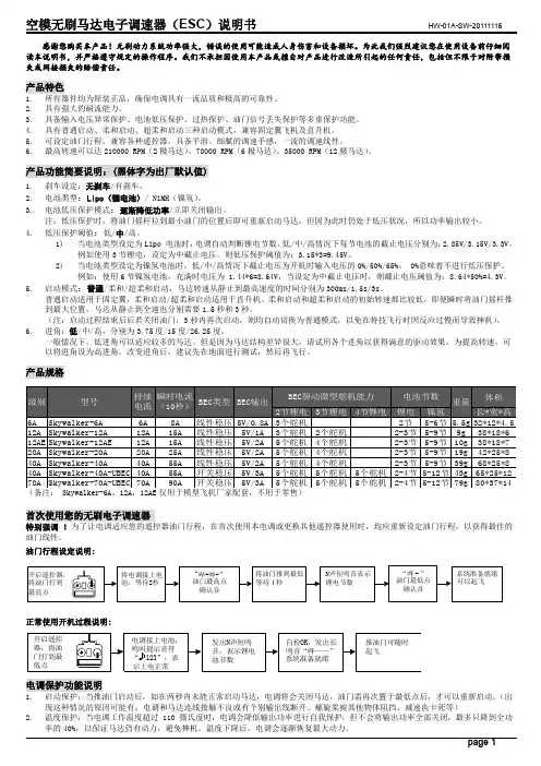
感谢您购买本产品!无刷动力系统功率强大,错误的使用可能造成人身伤害和设备损坏。
为此我们强烈建议您在使用设备前仔细阅读本说明书,并严格遵守规定的操作程序。
我们不承担因使用本产品或擅自对产品进行改造所引起的任何责任,包括但不限于对附带损失或间接损失的赔偿责任。
产品特色1.所有器件均为原装正品,确保电调具有一流品质和极高的可靠性。
2.具有强大的耐流能力。
3.具备输入电压异常保护、电池低压保护、过热保护、油门信号丢失保护等多重保护功能。
4.具有普通启动、柔和启动、超柔和启动三种启动模式,兼容固定翼飞机及直升机。
5.可设定油门行程,兼容各种遥控器。
具备平滑、细腻的调速手感,一流的调速线性。
6.最高转速可以达210000 RPM(2极马达)、70000 RPM(6极马达)、35000 RPM(12极马达)。
产品功能简要说明:(黑体字为出厂默认值)1.刹车设定:无刹车/有刹车。
2.电池类型:Lipo(锂电池)/ NiMH(镍氢)。
3.电池低压保护模式:逐渐降低功率/立即关闭输出。
注:低压保护时,将油门摇杆拉到最小油门的位置后即可重新启动马达,但因为此时仍处于低压状况,所以功率输出较小。
4.低压保护阈值:低/中/高。
1)当电池类型设定为Lipo 电池时,电调自动判断锂电节数,低/中/高情况下每节电池的截止电压分别为:2.85V/3.15V/3.3V。
例如使用3节锂电,设定为中截止电压,则低压保护阈值为:3.15*3=9.45V。
2)当电池类型设定为镍氢电池时,低/中/高情况下截止电压为开机时输入电压的0%/50%/65%。
0%意味着不进行低压保护。
例如:使用6节镍氢电池,充满时电压为 1.44*6=8.64V,当设定为中截止电压时,则截止电压阈值为:8.64*50%=4.3V。
5.启动模式:普通/柔和/超柔和启动,马达转速从静止到最高速度的时间分别为300ms/1.5s/3s。
普通启动适用于固定翼,柔和启动/超柔和启动适用于直升机。
S-5! 安装指南说明书

4
Above illustrations show S-5-N clamp. S-5-N & S-5-N Mini
22ga steel 24ga steel and
Inch Pounds Foot Pounds
ห้องสมุดไป่ตู้
160–180
13–15
130–150
11–12.5
Nm 18–20 15–17
S-5-N 1.5 & S-5-N 1.5 Mini
4. Tighten the setscrews using a screw gun* and the included screw gun bit tip. Setscrews should be tensioned and re-tensioned as the seam material compresses, i.e. tighten the first setscrew, then the second; then repeat until each setscrew achieves the recommended torque. The setscrews will dimple the seam material but will not penetrate it. When relying on published load values, setscrew tension should be verified periodically using a calibrated torque wrench as indicated below to ensure the tool is consistently achieving the proper torque range.
Skydrop控制器安装与设置说明书

STEP 2: MOUNT WALL PLATE
1. Locate the Wall Plate in the packaging. The wall plate will be placed in the general location of the old controller. You need to first determine the type of install you will be doing:
• If your wire is coming UP the wall, there is a provision for bottom entry.
• If your wire is coming OUT OF the wall, there is likewise a provision for back entry.
some brands of controllers)
STEP 1: REMOVE OLD CONTROLLER
1. First, unplug your existing controller from the wall electrical outlet.
2. Access the wiring compartment of the controller and locate the zone wires. You have been provided with adhesive stickers to mark each of the zone wires.
2. Choose which location of entry you will use for your controller.
3. Insert zone control wires, along with the skydrop AC power supply through the provisioned channels. (Note: if your control wires are coming from within your wall you will want to insert wires through the back channel, and your AC power supply through the bottom channel, allowing it to be strung to the nearby power supply).
X5 电子版说明书(中文)
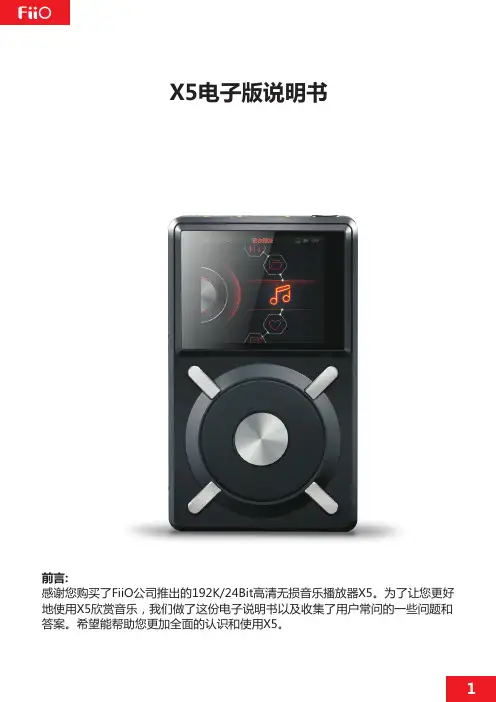
X5电子版说明书前言:感谢您购买了FiiO公司推出的192K/24Bit高清无损音乐播放器X5。
为了让您更好地使用X5欣赏音乐,我们做了这份电子说明书以及收集了用户常问的一些问题和答案。
希望能帮助您更加全面的认识和使用X5。
一、产品介绍二使用介绍三、固件升级四、菜单操作图解五、菜单操作(文字详解)六、USB DAC 功能 安装驱动前的准备驱动安装方法以及步骤 操作方法七、使用技巧八、X5常见问题解答1) 关于充电 2) 传输歌曲 3) 固件升级 4) 储存 5) 音乐播放 6) 其他操作7) 与其它音频设备连接、按键与接口3目录3-4456-9999-111112131314141516 1718为一台USB DAC设备使用。
下面我们结合一些图示来介绍下X5的使用介绍及使用技巧。
111216数据充电接口音量快减:长按音量微减(-):短按⑨耳机接口 复位键电源:长按/锁屏:短按①电源/锁屏键:关机状态按住2秒松开,稍候即可开机;开机状态长按3秒即可关机(长按10秒强制关机);开机状态下短按即可打开/关闭屏保。
②26万色IPS 高清显示屏(分辨率:400X360):显示操作界面及其他信息,配合按键操作和设置产品。
③快捷键/主菜单:短按弹出/收起当前状态的快捷菜单(待机界面短按进入播放设置);长按返回主界面。
④返回键/主菜单:在任何界面下,短按一次,逐级返回上一级菜单;在任何界面下,长按返回主菜单界面,在主菜单界面,短按会再返回播放界面(如有曲目正在播放时)。
主菜单:长按④返回键:短按(快进:长按⑧下翻/下一曲):短按圆盘(选择):360°旋转⑤②显示屏⑩充电指示灯⑥确定/音量调节菜单:长按播放/暂停主菜单:长按③快捷键:短按(快退:长按⑦上翻/上一曲):短按⑤圆盘:360°旋转,顺时针转可以向下/右翻动,切换选择下一个设置选项,调整设置项目数值;逆时针转可以向上/左翻动,切换选择上一个设置选项,调整设置项目数值。
IO服务器Wonderwaer产品安装说明书V1.1

单位简称分发列表修改列表修订版本列表目录1.概述 (4)2. I/OSERVER FSGATEWAY 2.0的安装 (5)3. WONDERWARE INSQL 9.0 组件IDAS (11)4. WONDERWARE INSQL 9.0 SP2 (15)5.授权的安装 (17)1.概述本文件是I/O服务器Wonderwaer产品安装说明书的流程及具体方法,为了保证软件安装的正确性,未来工作的顺利进行和有效维护,以及便于工作人员之日常操作,特此做出如下的操作指引。
I/O服务器主要是12台服务器的2台一主一备,进行数据的采集。
操作员站的具体配置如下:操作系统:Windows 2008 Server应用软件:Wonderware InSql 9.0 组件IDAS和I/Oserver FSGateWay 2.02.I/OServer FSGateWay 2.0的安装FSGateWay 2.0是Wonderware I/O、DA Server的一个,根据该服务器的需要我们在该计算机只安装这一个软件即可。
下面介绍具体安装过程:步骤1:将Device Integration安装盘放入计算机中(或者是在计算机上找到Device Integration 的文件夹,点击安装运行),会自动弹出如下画面。
步骤2:如下图所示进行选择。
步骤3:点击右侧画面中的“FSGateway”,出现如下所示的提示画面。
步骤4:点击运行,出现如下所示的提示画面。
步骤5:点击运行,出现如下画面。
此过程是安装产品时的所需的必备组件列表,如果没有准备其中的一些产品或功能,它们所需的必备组件也可以不必安装,必备组件一旦安装将无法卸载。
点击对话框下方的安装必备组件按钮,开始安装必备组件。
完成后出现如下画面。
步骤6:点击运行,出现如下画面。
步骤7:点击下一步,出现如下画面。
步骤8:点击下一步,出现如下画面。
步骤9:进行用户账户及密码的设定,设置用户名及密码供节点及数据服务器间通讯使用。
2018-2020 Jeep Wrangler和Gladiator推杆自启始系统安装指南说明书
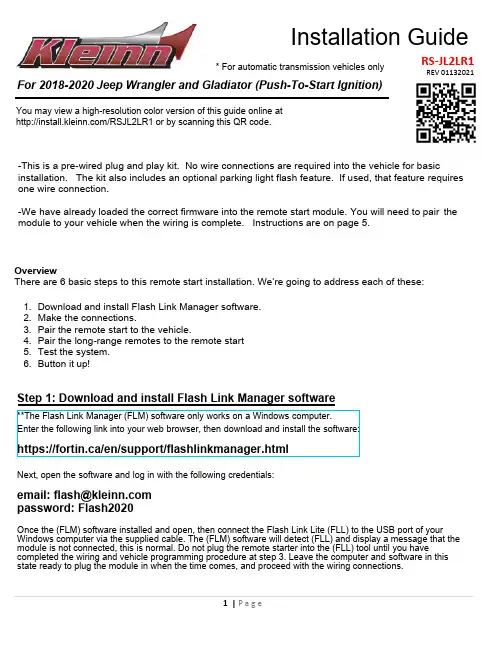
Installation GuideFor 2018-2020 Jeep Wrangler and Gladiator (Pus h -To-Start Ignition)RS-JL 2LR1*For automatic transmission vehicles only-This is a pre-wired plug and play kit. No wire connections are required into the vehicle for basicinstallation. The kit also includes an optional parking light flash feature. If used, that feature requires one wire connection.-We have already loaded the correct firm ware into the remote start module. You will need to pair t he module to your vehicle when the wiring is complete. Instructions are on page 5.OverviewThere are 6 basic steps to this remote start installation. We’re going to address each of these: 1.Download and install Flash Link Manager software.2.Make the connections.3.Pair the remote start to the vehicle.4.Pair the long-range remotes to the remote start5.Test the system.6.Button it up!Step 1: Download and install Flash Link Manager software**The Flash Link Manager (FLM) software only works on a Windows computer.Enter the following link into your web browser , then download and install the software :https://fortin.ca/en/support/flashlinkmanager.htmlNext, open the software and log in with the following credentials:email:****************password: Flash2020Once the (FLM) software installed and open, then connect the Flash Link Lite (FLL) to the USB port of your Windows computer via the supplied cable. The (FLM) software will detect (FLL) and display a message that the module is not connected , this is normal . Do not plug the remote starter into the (FLL) tool until you havecompleted the wiring and vehicle programming procedure at step 3. Leave the computer and software in this state ready to plug the module in when the time comes, and proceed with the wiring connections.REV 01132021You may view a high-resolution color version of this guide online at /RS JL2LR1 or by scanning this QR code.Where to make connections:Step 2: Wiring2At Push-to-Start button.At parking light switch..At CAN junction,behind the glovebox.When you open up your remote start, you’re going to see a bunch of loose wires in a bundle. Don’t be intimidated ! T he system wiring overview and steps below will show you the specific wires that you’re going to need and where they connect in your vehicle. Any wires that are not shown to connect in this guide will not need to be connected.R emove the plastic shroud below the steering wheel in the vehicle . This will allow access to the under dash driver's side location of the vehicle. The remote start brain will be mounted in this location. Before you start wiring, look for a place under the dash where there’s some open space that will fit the module. Pay attention to moving parts like the pedals, e-brake and steering column. Be sure to route your wiring away from those areas. Be careful not to break the panels –especially in cold weather.Next, open the glove box on the passenger's side and release the tabs on both sides to open the glove box past it's normal stopping point. The glove box can then be lifted off its hinges and removed. This will allow access to the CAN Junction connectors.Preparation:System OverviewOptional wiring connectionsParking lights - This will serve as a visual indicator that the vehicle is running. If you wish to have this option , locate the Green/Red wire in the bundle of unused, loos e wires. Connect the Green/Red wire to the vehicle White/Brown parking light wire at the back of the parking light switch , Pin position 1 as shown in the system wire diagram. To assist with identification, a photo of the back of the parking light switch can be found on Page 2. This is a 'tap-on' connection. Do not cut the W hite/B rown parking light wire in the vehicle. Simply attach the Green/Red wire from the remote start T-harness on to the white/brown parking light wire.1.Connect the CHR7-A harness. The male OEM plug on the back of the vehicle Push-To-Start button will be accessible to the right of the steering column. Reach in with your hand or dismount the push-to-start button to locate and disconnect the plug from the back of it. Then, connect the male t-harness plug into the back of the vehicle push-to-start button, and plug the female t-harness plug into the male OEM plug.2.Connect the CHR7-B harness. Route the end of the harness with the two 2-Pin CAN Junction plugs behind the center console and to the area below the glove box.3.Plug the Green connector in to any open slot in the Green CAN junction block.4.Plug the White connector in to any open slot in the White CAN junction block.Hood Pin - This is an important safety feature. It de-activates the remote start w h ile t he hood is open to prevent injury from accidental remote starting while working under the hood. Most vehicles will have an OEM hood pin that is read by the remote start module. In these vehicles, installation of the aftermarket hood pin is unnecessary.If you are uncertain as to whether or not your vehicle had factory hood pin - after you complete the remote start installation and test the system, try remote starting the vehicle with the hood open. It the vehicle will not start, you have a factory hood pin. If the vehicle does start, you do not. If you install the hood pin, it must be mounted so that:a.The body of the pin is mounted to metalb.The pin is depressed when t he hood is closed and released when the hood is open.Connect the Dark Blue wire from the loose wire bundle to the hood pin (you may need to extend the wire). The ground signal from the hood pin on that Dark Blue wire will disable the remote start system.Valet Switch - The valet switch can also be used to disable the system.a.Connect one side of the switch to the Dark Blue wire from the loose wire bundleb.Connect the other side of the switch to groundBoth the hood pin and the valet switch can be connected to the Dark Blue wire.STEP 3: ProgrammingOnce the T -harness has been connected , the remote start module is ready to be programmed.15Do not press the brake pedal.Press the START/STOP button twice to turn ON the ignition.willturn off.The BLUE LED The RED and YELLOW LEDs will alternated.Press the START/STOP button once to turn OFF the ignition.Once you have the alternating red and yellow LED's, unplug all the connectors from the remote start brain. Be sure to disconnect the 4-pin black data link plug last.Next, it's time to b ring the remote starter module to your computer and plug it into the supplied four-pin plug from the Flashlink Lite (FLL). For a video on how to do these steps visit: /flashlinkThe software will detect you plugging it in and will automatically load the current settings.The first step is to select your vehicle. Click the three bars at the top of the Red bar on the upper left corner of the screen. Select your make, year, model, key type and then click load settings. Do not change any other dropdowns or any options - we have already done these settings for you.Wait while the updater reads data from the remote starter. Once it is done it will update the remote starter and you will need to wait again. You will see a status bar at the bottom of the screen.When it gets to 100%,the Dcryptor process is complete.You can now unplug the remote starter module and plug it back into the connectors in your vehicle. Make sure to plug in the power connector first and then the rest of the plugs afterward. Do not hold theprogram button down when you plug the connectors back in.Next, click the Dcryptor tab. Then click on the Send data button.1Unplug the 4 Pin (Data-Link) connector from the EVO module .2Press and hold the programming button:Reinsert the 4-Pin (Data-Link) connector.3Release the programming button when LEDs are BLUE & RED.If the LED are not solid BLUE and RED disconnect the 4-Pin connector (Data-Link) and go back to step 1.4Press and hold the programming button until the Blue and RED LED turn back ON.The Blue and Red LED will go Off and back On.5FLASHDo not press the brake pedal.Press the START/STOP button twice to turn ON the ignition.The Blue, Yellow and Red LEDs will turn On. The antenna will fl a sh rapidly.The remote is now programmed.Step 4: Pair the remotes to the remote starterIf you have any installation questions or problems, call for tech support520.579.1531Copyright 2021 Kleinn Automotive AccessoriesStep 5: Test the SystemStep 6: Close it UpNow gather up all of your wiring and neatly bundle it together using zip ties or electrical tape. Find a secure place to put the remote start module and use zip ties to secure it. Make sure that the remote start wires are not near any moving parts on the steering wheel, pedals or emergency brake! Re-Install any panels that were removed to gain access to key switch in reverse order they were removed. ENJOY!Once all wiring and programming are done, you should test the system to make sure everything is working properly before you close up the installation.1x 0.5 secondsLOCKPress the button 1x (0.5 seconds) : Locks all doors, arm the anti-theft system and activates the Alarm (if installed).2x 0.5 secondsUNLOCKPress the button 2x (0.5 seconds): Un-locks all doors, disarms the anti-theft system and deactivates the Alarm (if installed).1x3 secondsSTART OR STOPPress and hold the button for 3 seconds: Remote-start the vehicle. If the engine is ON : the engine will turn OFF .。
X5中文使用手册
• 只能将设备用于其特定的用途。有关资料请与公司的经销商联系。
• 让软管和电缆远离公共区域、尖锐边缘、移动部件及热的表面。
• 不要扭绞或过度弯曲软管或用软管拽拉设备。
• 儿童和动物要远离工作区。
• 要遵照所有适用的安全规定进行。
高压铝质部件危险
在压力设备中使用与铝不兼容的流体可导致严重的化学反应和设备破裂。未遵循本警告可导致死亡、严重受伤或财 产损失。 • 不得使用 1,1,1- 三氯乙烷、二氯甲烷、其它卤代烃溶剂或含有这些溶剂的流体。 很多其它流体可能含有与铝发生反应的物质。联系您的材料供应商以了解兼容性信息。
操作
Magnum X5 和 X7 无气喷涂机
3A1776C
ZH
- 用于建筑油漆和涂料的便携式喷涂应用 - 不得用于爆炸性环境 -
型号:
M最大ag工n作um压力X:52(071巴6J,72510兆)帕- A(系30列00 磅 / 平方英寸)
包括:
• 0.91 升 / 分钟 (0.24 加仑 / 分钟)立式安装喷涂机 • SG2 喷枪 - 手册 312830 • 0.635 cm (1/4 英寸)x 7.5 m (25 英尺)软管
• •
接如果地您插对头接安地装说不明当不会十导分致理遭解受,电或击不的知危道险该。产品是否已正确接地,请与一位合格的电工或维修人员联系。
• 不要改造所提供的插头,如果无法将其插入电源插座内,让一位合格的电工安装一个好的电源插座。
• 此产品用于在标称电压为 230V 的电路上使用,其接地插头与下图所示的插头类似。
将喷嘴和护罩装到喷枪上 . . . . . . . . . . . . . . . . . . 12 喷涂技术 . . . . . . . . . . . . . . . . . . . . . . . . . . . . . . . 12 启动 . . . . . . . . . . . . . . . . . . . . . . . . . . . . . . . . . . . 12 疏通喷嘴 . . . . . . . . . . . . . . . . . . . . . . . . . . . . . . . 13 扣动喷枪 . . . . . . . . . . . . . . . . . . . . . . . . . . . . . . . 13 瞄准喷枪 . . . . . . . . . . . . . . . . . . . . . . . . . . . . . . . 13
信达小黑完全傻瓜级操作说明手册之欧阳家百创编
信达小黑完全傻瓜级操作说明手册欧阳家百(2021.03.07)信达小黑标准称呼应该是Sky-Watcher BKP 150/750 牛顿反射式天文望远镜。
小黑主镜分为普通版和摄影版两种原配赤道仪分为EQ3-D和EQ3-W两种本文为了方便,全文将以普通版小黑主镜搭配钢腿EQ3-W赤道仪为例,进行讲解。
收到你购买的小黑后,你应该首先检查其各个零件是否齐全。
普通版小黑主镜的包装箱内应该有:主镜1个,1.25英寸转接环1个(一般已经装在调焦座上了),2英寸转接环1个,六角形螺丝刀1个(一般和2英寸转接环在一起),抱箍环2个(一般已经装在了主镜上),鸠尾板1个(一般已经和抱箍环连接好了),寻星镜支架1个,6*30光学寻星镜1个,25mm目镜1个,10mm目镜1个,2倍巴罗透镜1个,还有1个不起眼的橡皮圈(LZ的是在寻星镜支架上)。
钢腿EQ3-W赤道仪的包装箱内应该有:钢腿三脚架1个,赤道仪本体1个,附件盘1个,小铁片一样的扳手1个,平衡锤2个(一大一小),平衡锤杆1个,中心杆1个(上面还有2个固定螺栓),微调杆2个,鸠尾板1个(怎么又来一个?),平衡锤杆锁紧螺帽1个。
安装过程中你需要一把十字口螺丝刀,请自备。
安装支架:1.安装三脚架,这个不需要我说了,只是说一下,脚架上有N字样的腿对着北边。
以下是复制的一段内容:【1. 竖起三脚架并使其金属支架完全展开。
三脚架便能在水平面上保持站立。
一旦三角架组装完毕,您便能调节它的高度。
2. 逆时针松开三脚架腿上的锁紧螺栓,使得三脚架腿能够进行调节。
3. 将三脚架脚的内芯从底部拉出来到您所需要的高度。
4. 顺时针旋紧每条腿上的锁紧螺栓使得每条腿都固定好。
5. 三脚架的标准高度是33 英寸,完全展开后可达到 47 英寸。
请注意,三脚架在最低高度时最为稳定。
】2.找到赤道仪上的方位角调节螺栓(图不好找,用CG-4赤道仪的图,和EQ3-W没太大的区别),将螺栓旋出赤道仪的方位角槽。
MAG Codex X5系列游戏桌面产品说明说明书
Rule your gaming empirewith minimalist styleMAG Codex X5 series gaming desktop is designed for entrygamers, features Intel processor and the latest NVIDIA RTXseries graphics card, providing the best gaming experience.Exclusive thermal solution with the best air cooling, promisethe longer system performance, RGB lighting effect designwith tempered glass, show off your personally gaming style,MSI MAG Codex 5 series will lead the players to conquer thewonderful battles.Selling PointsWindows 11 家庭版最高支持Intel Core i9-12900K处理器最高支持MSI GeForce® RTX 3090显卡支持DDR5内存支持PCI-E 5.0优化风道设计两种侧板,可根据您的喜好选择支持Mystic Light 炫光系统简易升级设计高速M.2固态硬盘USB 3.2 Gen 2x2 Type-C接口Picture and logosSystem I/O-Ports1.1x Headphones / 1x Microphone2.1x USB 3.2 Gen 1 Type C / 2x USB 3.2 Gen 1 Type A3.Flash BIOS button4.2x USB 2.0 Type A / 1x PS/2 Combo port5.1x HDMI out / 1x Display Port out6.2x USB 3.2 Gen 1 Type A / 2x USB 2.0 Type A7.1x USB 3.2 Gen 2x2 Type C / 1x USB 3.2 Gen 2 Type A/ RJ45 (2.5G LAN)8.2x WiFi Antenna9.6x Audio jacksSpecificationOperating Systems Windows Windows 11 HomeProcessor CPU model Intel Core i7-12700KF CPU Clock 3.6GHzCPU Cores12CPU TDP125WCPU Cache25 MB Intel® Smart Cache CPU Threads20CPU Cooling Liquid cooling 150WChipset Motherboard Chipset Z690Discrete Graphics VGA I/O Port HDMIx1, Display Portx3Graphics Card GeForce RTX 3080 Ti VENTUS 3X 12G Graphics Card VRAM12GMemory Memory Capacity32GB(32GB*1) Memory Type DDR5 SDRAM Memory Speed2400(4800)MHz Memory Module Form Factor U-DIMM Memory Slot (Total/Free)4/3Memory Max Capacity Max 128GBStorage Total SSD Storage Capacity1TBTotal HDD Storage Capacity2TB*1M.2 Slot (1) Installed SSD1TB*1M.2 Slot (1) Interface PCIe GEN4x4 NVMe M.2 Slot (1) Form Factor M.2-2280 M-KEY M.2 slots (Total/Free)4/3HDD (1) RPM7200RPMHDD (1) Form Factor 3.5 inchHDD (1) Interface SATA GEN33.5" Drive Bays (Total/Free)2/12.5" Drive Bays (Total/Free)2/2ODD(Type)N/AODD Height N/AODD Type N/ACommunications LAN Controller Intel I225-VWireless LAN Controller INTEL/AX211.NGWG.NV Wireless LAN standard Wi-Fi 6E+BT Bluetooth Version 5.2Audio Audio Codec Realtek ALC897 Audio Support7.1 Channel HD AudioI/O Ports (Front)Thunderbolt N/A USB 5Gbps (USB 3.2 Gen 1 Type-A)2 USB 5Gbps (USB 3.2 Gen 1 Type-C)1 Audio Mic-In (Front)1 Audio-Out (Front)1I/O Ports (Rear)USB 20Gbps (USB 3.2 Gen 2x2 Type-C)1USB 20Gbps (USB 3.2 Gen 2x2 Type-A)1USB 5Gbps (USB 3.2 Gen 1 Type-A)2USB 480Mbps (USB 2.0 Type A)4LAN Ports (RJ45)1WiFi Antenna N/A HDMI™1x (v2.0) DP out1x (v1.4) PS/21Audio Jack Total (Rear)6Flash BIOS Button1Power Rated Wattage850WEfficiency Rating80plus Gold Form factor ATXPower Supply Type POWER SUPPLYIn The Box Keyboard Interface N/A Mouse Interface N/A Power Cord1 AC Adaptor N/A Warranty Card2 Quick Guide3 User Manual N/A VESA Mount kit N/A Keyboard N/A Mouse N/ARegulatory Compliance Storage Operating Temperature Range0° C ~ 35° C ; -20° C ~ 60° C Storage Operating Humidity Range0% ~ 85%;0% ~ 90%CertificationsFCC(Class B)CB/CEUL(CUL)BSMIVCCIRCM(C-Tick)Dimension & Weight Product Dimensions (WxDxH) (mm)195 x 514.8 x 466Product Dimensions (WxDxH) (inch)7.68 x 20.27 x 18.35Inside Carton Dimensions (WxDxH) (mm)N/AInside Carton Dimensions (WxDxH) (inch)N/AOuter Carton Dimensions Standard (WxDxH)(mm)575(W/O KB) x 320(W/O KB) x 660(W/O KB) Outer Carton Dimensions Standard (WxDxH)(inch)575(W/O KB) x 320(W/O KB) x 660(W/O KB) Weight (Net kg)12.4Weight (Gross kg)16.93Product Volume (Liters)40Warranty Warranty N/ABarcode Info EAN4719072973339 UPC824142293225。
天行者 Skywalker 1900 安装组装说明书
Sky-Walker Pro Installation ManualThank you for purchasing the Sky-Walker Pro plane.The Sky-Walker Pro is designed for First-Person-Vision (FPV) application specifically.Due to the high wing and push propdesign,the on-board camera could have a perfect view without being blocked.The large fuselage compartment design provides conveniency to contaln almost any hobby FPV equipment.Other than that,the Sky-Walker Pro is also suitable for the beginners to leam flying as a high stable trainer plane.Before you start the installation,please read this manual carefully to have an overall idea of what to do.In the same time,please check all parts before you begin.If you find any missing or defective parts,please contact your local dealer.1,Required for Installation and Operation:1.1Required RC Equipments:The below listed RC gears are not included.They may need to be purchased separately.For details,please check with your local hobby stop.-Minimum 3-4 channel radio control system-Minimum 2 pieces of 9g micro servos or similar.4 servos are needed for full control of aileron,elevator and rudder- 2 pieces of 25~30cm servo extension cables for aileron servos-AXI 2814KV920 out-runner brushless motor or equivalent-45A or above brushless ESC with 25~30cm length of the power input wire-APC9060E propeller or equivalent-5000mAh 4S lithium-polymer battery pack or similarYou may need the following for FPV application:-DC powered Camera-Pan/tilt camera mount with servos- 6 or more channel radio control system,instead of 3~4 channels for basic flying-Wireless transmitter and receiver for on-board video transmission-On-Screen-Display(OSD)system-1000mAh 3S lithium-polymer battery pack or similar for the camera(refer to the manual of the camera system)3- A 490-1hgfrewq1.2Required Tools and Material for Installation:-Phillips screwdriver&allen key-Sharp hobby knife-Hobby scissors-Needle nose pliers-Wire cutters-Marjer pen-Foam double-sided tape -Fibre tape-Paper tape-Cable tight-Male&female Velcro tape -Hot glue and hot glue gunParts listing :Free the aileron surfaces from the wing pieces with sharp hobby knife if the aileron control is needed.Trim off the un-necessary EPO material.Step2:Apply a thin layer of the EPO glue for the 2 EPO carbon tube slot covers .It is not recommended to apply glue on the contact surface between the EPO material and carbon tubes,unless you are planning to join the wing pieces permanently.Similarly,Apply a thin layer of the EPO glue on the wing pieces at the joint area of the 2 EPO carbon tube slot covers.Step4:Wait for about 1~2 minutes gor the glue to solidified slightly before placing the 2 carbon tube covers.机翼碳片安装;共两根碳片,在机翼碳片槽内均匀滴入胶水,再将碳片卡入槽内压紧,即可固定。