中国电信集团北京市电信有限公司新产品说明书
天翼电子产品使用指南说明书
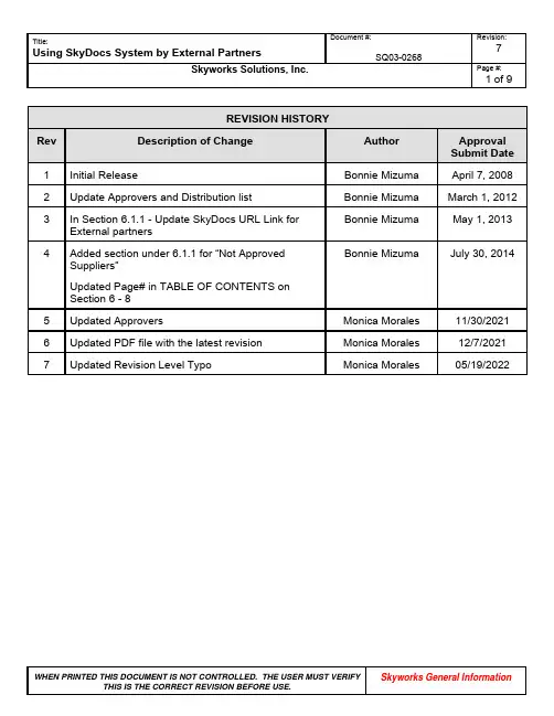
1 of 9REVISION HISTORYRev Description of Change Author ApprovalSubmit Date1 Initial Release Bonnie Mizuma April 7, 20082 Update Approvers and Distribution list Bonnie Mizuma March 1, 2012Bonnie Mizuma May 1, 2013 3 In Section 6.1.1 - Update SkyDocs URL Link forExternal partners4 Added section under 6.1.1 for “Not ApprovedBonnie Mizuma July 30, 2014 Suppliers”Updated Page# in TABLE OF CONTENTS onSection 6 - 85 Updated Approvers Monica Morales 11/30/20216 Updated PDF file with the latest revision Monica Morales 12/7/20217 Updated Revision Level Typo Monica Morales 05/19/20222 of 9 TABLE OF CONTENTSSection Section Name Page Number(from) Page Number(to)1.0 Purpose 2 22.0 Scope 2 23.0 Process Objectives 2 24.0 Internal Applicable / External Reference Documents 3 35.0 Acronyms / Terminology and Description / Definition 3 36.0 Procedure 4 87.0 Quality Records (Process Outputs) 9 98.0 Document Responsibilities 9 91.0 PurposeThe purpose of this document is to explain Skyworks external documenation system (SkyDocs) to our partners.2.0 ScopeThis work instruction applies to Skyworks partners that have a SkyDocs account3.0 Process Objective(s)Ensure that Skyworks’s requirements are:∙Known by our partners.∙Accessible to be reviewed in real time.∙Well communicated by improving our partners documentation access3 of 94.0 Internal Applicable / External Reference DocumentsINTERNAL APPLICABLE DOCUMENTSDocument Number Document TitleSQ01-0001 Skyworks Quality ManualSQ02-0020 Skyworks Supplier Quality ManualEXTERNAL REFERENCE DOCUMENTSDocument Number Document TitleNone None5.0 Acronyms/ Terminology and Description / DefinitionAcronyms / Terminology Description / DefinitionPartner SubCon or Supplier that provides critical product or services toSkyworks.SkyDocs Web-based enterprise-wide software portal used to share documentsinternally and externally.Subscription SkyDocs function that allows to send automatic e-mail notifications topartners4 of 9 6.0 Procedure6.1 PROCEDURE6.1.1 Accessing SkyDocs6.1.2 Subscription from SkyDocs6.1.1 Accessing SkyDocsSkyDocs is a Web-based enterprise-wide software portal used by Skyworks to share documents internally and externally.SkyDocs can be accessed by using the following link:/skydocs/skydocs.nsfNote: System Requirements: Please ensure you are using Internet Explorer 5.5 or greater. Netscape, Mozilla, Firefox are not supported.The following paragraphs will describe the steps necessary to access documentation in SkyDocs.For Qualified / Approved Suppliers and Vendors:Step 1:∙Access to the link above to login.∙Please enter your Username and Password.Note: If you don’t see the login screen appear, please make sure your window is expanded and scroll all the way down.5 of 9 Step 2:∙Once you are logged into the SkyDocs system, you will be able to view the folder called: “Supplier Distribution Area”, click on the folder.Step 3:∙Identify the name of your company and click on the applicable folder.6 of 9 Step 4:∙Access to the document that you will like to review.For Un-Qualified / Un-Approved Suppliers and Vendors: (Suppliers and Vendors to be qualified and approved by Skyworks)Step 1:∙Access to the link above to login.∙Please enter your Username and Password.Note: If you don’t see the login screen appear, please make sure your window is expanded and scroll all the way down.7 of 9Step 2:∙Once you are logged into the SkyDocs system, you will be able to view the folder called: “Suppliers to be Qualified”, click on the folder.Step 3:∙Identify the name of your company and click on the applicable folder.8 of 9Step 4:Access to the document that you will like to review.6.1.2 Subscription from SkyDocsEvery time a file is added to your company’s profile, an automatic e-mail will be sent to the contact person, as the example below.It is our partner’s responsibility to review, distribute and implement Skyworks requirements in their process.9 of 9Who WhatPartners Ensures the review, distribution and implementation of Skyworkslatest revisions of documents.Document Control Publishes and ensures availability of latest document revisions inSkyDocs.7.0 Quality Records (Process Outputs)Not Applicable8.0 Document ApproversWhoQuality System ManagersSubCon ManagerSourcing Manager。
电信CDMA数字光纤直放站用户手册
CDMA数字光纤直放站说明书北京邦讯技术有限公司BOOMSENSECDMA数字光纤直放站使用说明书北京邦讯技术有限公司BEIJING BOOMSENSE TECHNOLOGY CO.,LTDAll rights reserved*安全注意事项*任何参与安装、操作和服务直放站的人员必须理解并遵守下面各项要求:◆直放站设计目的是:接收放大基站的信号,并重新辐射信号到覆盖区;接收放大覆盖区的移动台信号,并重新辐射信号到基站。
这是直放站的主要目的,非经专业人员指导,不能有其他任何用途。
◆由外部干线引入的电源必须通过接地引线进行接地,并符合当地有关规定。
◆由外部干线引入的电源的电平是危险电压电平,可能会引起电击。
对直放站进行任何工作前请先关闭外部电源。
当外部电源打开时,只有经过授权的服务才可以对直放站进行操作。
●◆在对室外直放站操作时,要固定好已打开的直放站的门。
否则,吹风会使直放站的门无意中关闭,可能会压到您的手指或碰到您的头。
●◆当在离地面高处操作直放站时,也就是在双桅杆上或柱子上操作直放站时,要特别小心,不要让部件或整个直放站掉下来,以免砸自己或下面的人。
●◆任何直放站,包括此直放站,将产生无线信号。
任何人,一靠近直放站或直放站天线,将极大地暴露在电磁场中,这可能会对您的身体造成损害。
静电* 静电一般不会对人体造成损害,但如果不小心处理,几乎肯定会对直放站部件造成损害。
* 直放站上某些部件和印刷电路板上的部件很容易遭到静电损害。
* 千万不要接触电路板或未绝缘的电容器表面,除非绝对需要。
* 如果必须处理电路板或未绝缘的电容器,使用ESD(静电防护)保护装置,或者,首先把手接触直放站底盘并且您的脚始终不离地。
* 千万不要让您的衣服接触到印刷电路板或未绝缘的电容器。
* 印刷电路板要保存在ESD防护袋里。
目录*安全注意事项* (3)一、概述 (6)1.1系统简介 (6)1.2应用介绍 (7)1.3产品特点 (8)二、安装和连接 (10)2.1近端单元安装 (10)2.2远端单元安装 (10)2.3近端单元的连接 (12)2.4远端单元的连接 (16)2.5一近端单元拖多个远端单元的连接 (17)三、试运行设置 (19)3.1远端单元加电 (19)3.2近端单元加电 (19)3.3指示灯说明 (19)3.4系统设置 (20)四、模块功能描述 (21)4.1主要模块描述 (21)4.3远端单元内部模块图 (23)4.4原理框图 (24)五、监控平台安装与操作 (27)5.1硬件要求 (27)5.2操作说明 (27)5.3监控软件操作要求 (28)5.4模块操作 (38)5.5链路增益设置 (40)六、故障处理 (43)6.1维护与维修注意事项 (43)6.2紧急情况处理 (43)6.3故障处理流程 (44)附录一:技术指标 (45)一、概述1.1系统简介CDMA数字光纤射频拉远系统是指将CDMA射频信号经A/D转换为数字信号,通过对数字信号进行处理、滤波和采用数字光纤技术进行传输,并经D/A转换和放大,实现CDMA射频信号的拉远传输的设备和系统。
京信通信2100MHz_FDD-LTE数字光纤直放站技术规格书
京信通信2100MHz FDD-LTE数字光纤直放站技术规格书1用途京信通信2100MHz FDD-LTE数字光纤直放站是一种直接耦合基站信号,采用数字传输方式,将信号传输至射频拉远单元进行覆盖的无线网络解决方案。
整机系统由数字接入单元,以下简称“近端机”和射频拉远单元,以下简称“远端机”组成。
该产品是基于采用数字中频技术的光纤传输,克服模拟光纤传输时信号的信噪比恶化的缺点,具有大动态、低噪声的优点,并且在数字中频的基础上开发多种功能,比如菊花链组网、星型组网、混合组网、环形组网、远端光旁路备份切换扩展功能、近端备份切换扩展功能、以太网接口、远程下载以及时延校准等功能。
2功能1)工作频段为上行1920MHz~1940 MHz,下行2110 MHz ~2130 MHz。
2)工作带宽20 MHz。
3)最大下行输出功率分为40W、60W功率等级。
4)下行采用数字预失真技术。
5)利用光纤传输,传输距离最远可达20km,信号在光纤传输时无损耗。
6)没有收发天线隔离问题,用户天线架设灵活,根据覆盖区域可选择定向或全向覆盖天线。
7)系统由近端机和远端机组成,支持星型、菊花链型、环型和混合型组网。
8)支持自动或手动时延校准,有效防止链型结构覆盖的同频干扰。
9)整机分室内机型和室外机型。
10)具备软件远程下载功能。
11)支持近端备份扩展功能。
12)远端光旁路备份切换扩展功能。
13)采用满足CPRI标准的HDLC进行远程监控通信,性能稳定。
14)本地监控功能(OMT):通过便携电脑对近端机或远端机进行增益设置及设备状态和工作参数查询,以及监控软件的更新下载,并且可以对主机和数字板分别进行复位设置。
同时用户可在近端机或远端机完成端对端的设置与查询。
15)配套完善的网管系统(OMC),通过近端机内置的CDMA MODEM或以太网与OMC建立远程通信,设备监控数据的远程传送采用“CDMA 1x PS域数传”或“CDMA短信”方式或以太网传输方式。
中国电信 天翼导航客户端说明书

中国电信天翼导航客户端使用手册(Brew版)版本V2.2日期:2010年11月目录1.“天翼导航”业务简介及产品特色 (3)1.1. 什么是“天翼导航”业务? (3)1.2. “天翼导航”有哪些特色? (3)2.温馨提示 (4)2.1. 免责声明 (4)2.2. 知识产权声明 (4)2.3. 使用声明 (5)3.“天翼导航”客户端的订购及退订 (5)3.1. “天翼导航”的订购 (5)3.2. “天翼导航”的退订 (6)4.“天翼导航”客户端使用说明 (6)4.1. “地图”功能介绍 (6)4.2. “导航”功能介绍 (8)4.3. “出行”功能介绍 (14)4.4. “语音助手”功能介绍 (18)4.5. “个人专区”功能介绍 (19)4.6. “公交换乘”功能介绍 (25)4.7. “路况”功能介绍 (28)4.8. “群组”功能介绍 (28)4.9. “查找周边”功能介绍 (29)5.附录 (30)5.1. “天翼导航”技术支持 (30)5.2. “天翼导航”标志介绍 (30)5.3. “天翼导航”常见问题解答 (31)6.GPS讲堂 (33)6.1. GPS (33)6.2. gpsOne (33)6.3. 定位原理 (34)6.4. 定位失败的原因 (34)1.“天翼导航”业务简介及产品特色1.1.什么是“天翼导航”业务?“天翼导航”产品是由中国电信提供的极具手机特性的GPS导航系统。
本产品是一套基于BREW平台开发的手机卫星导航系统,通过快捷简便的操作界面,丰富的城市导航地图,真人实时语音播报为展示平台,为用户提供了舒适便捷的全程驾驶导航功能。
您只需通过手机输入目的地或拨打“导航秘书”专线告知目的地,在行车途中的每一个转向、进出主路、弯道,以及经过交通电子眼监控路段前,系统都会及时给出相应的语音提示以及导向图标显示。
通过“天翼导航”软件您可以享受实时导航、自我定位、周边搜索、导航秘书等诸多新颖实用的服务功能,带您进入新的导航时代。
电讯通信有限公司产品说明书:RadioCom BTR-800 TR-800 TR-825
Thank you for choos i ng RadioCom TMTelex Com m u n i c a t ions would like to take this op p or t u n ity to thank you for choos i ng the RadioCom™BTR-800 Pro f es s ional Wire l ess In t er c om Sys t em. Many of the fea t ures in this prod u ct are the re s ult of years of de v el o p -ment work with many of the fea t ures de v el o ped from cus t omer feed b ack. We hope that your ex p e r i e nce with this prod u ct is a pleas a nt one and hope to pro v ide you with a con t in u i ng line of RadioCom™ prod u cts well into the fu t ure. In or d er to get the most out of your new wire l ess in t er c om sys t em, please take a few mo m ents to look through this book l et be f ore us i ng the prod u ct for the first time.-Telex Com m u n i c a t ions,Inc.Ta b le of Con t entsIn t ro d uc t ion..........................................................................1-1 Gen e ral De s crip t ion..........................................................................1-1 Sys t em Fea t ures.............................................................................1-1 BTR-800 Block Di a g ram......................................................................1-2 BTR-800 Base Sta t ion..................................................................2-1 Con t rols and Con n ec t ions - Front Panel..........................................................2-1 Con t rols and Con n ec t ions - Rear Panel...........................................................2-2 BTR-800 Spec i f i c a t ions.......................................................................2-3 TR-800 Beltpack.......................................................................3-1 Con t rols and Con n ec t ions - Top Panel............................................................3-1 Con t rols and Con n ec t ions - Rear Panel...........................................................3-2 TR-800Spec i f i c a t ions........................................................................3-3 TR-825 Beltpack......................................................................4-1 Con t rols and Con n ec t ions - Top Panel............................................................4-1 Con t rols and Con n ec t ions - Rear Panel...........................................................4-2 TR-825Spec i f i c a t ions........................................................................4-3 Ini t ial Equip m ent Set-Up...............................................................5-1 Un p acking.................................................................................5-1 An t enna Con n ec t ions.........................................................................5-2 An t enna Po l ar i za t ion.........................................................................5-2 Dis t ance Be t ween An t ennas...................................................................5-2 An t enna Place m ent..........................................................................5-2 Im p roving Re c ep t ion/In c reasing Range..........................................................5-4 Base Sta t ion Set-Up.........................................................................5-5 Lo c a t ion...............................................................................5-5 Power Con n ec t ion........................................................................5-5 Trans m it Switches........................................................................5-5 In t er n al Trans m it Switches.................................................................5-6 In t er c om Switch.........................................................................5-6 In t er c om In t er f ace........................................................................5-6 Dual Lis t en Func t ion a l i ty..................................................................5-8 Aux i l i ary In p ut/Out p ut....................................................................5-9 In t er n al Aux i l i ary In p ut Routing Switch......................................................5-9 Stage An n ounce /Re l ay Con t acts...........................................................5-10 Base Sta t ion Link .......................................................................5-11 Beltpack Set-Up...........................................................................5-12 Bat t ery In s tal l a t ion......................................................................5-12 An t enna Con n ec t ion.....................................................................5-13 Trans m it Mode.........................................................................5-13 Head s et Con n ec t ion.....................................................................5-13 Pre-Walk-Thru Check l ist...............................................................6-1 Sys t em Op e r a t ion......................................................................7-1 Fre q uency Plan Over v iew.....................................................................7-1 Fac t ory-Defined Group.......................................................................7-1 User-Programmable Groups...................................................................7-1 Sys t em Quick Start..........................................................................7-1 Base Sta t ion Op e r a t ion......................................................................7-2 Power.................................................................................7-2 Lo c al Head s et...........................................................................7-2 Por t a b le Sta t ion Con n ect..................................................................7-2 In t er c om A and B........................................................................7-2 Aux i l i ary...............................................................................7-2 Dis p lay Con t rast.........................................................................7-3 BTR-800 Menu Struc t ure.................................................................7-4 Main Screen Flowchart.................................................................7-4 Power-Up Screen......................................................................7-5 Op e r a ting Screen......................................................................7-5 Beltpack Ac t iv i ty Cod e Def i n i t ions........................................................7-5 Group/Chan n el Se l ect..................................................................7-6 Group/Fre q uency Se l ect.................................................................7-7 Fre q uency Ed it.......................................................................7-8 Clear Scan...........................................................................7-9 Spe c ial Key Se q uences................................................................7-10 Lock o ut.........................................................................7-10Copy...........................................................................7-101st Use De f ault...................................................................7-10Fac t ory De f ault...................................................................7-10-i-Ta b le of Con t ents(con t in u ed)TR-800Beltpack Op e r a t ion.................................................................7-11 Power/Lo c al Head s et V ol u me..............................................................7-11 Bat t ery Check..........................................................................7-11 Talk But t on............................................................................7-11 Mi c ro p hone Gain.......................................................................7-11 Chan n el Se l ect But t on...................................................................7-11 Stage An n ounce (SA)....................................................................7-11 Wire l ess Talk Around (WTA)..............................................................7-11 TR-800Beltpack Menu Struc t ure.........................................................7-12 Power-Up Screens....................................................................7-13 Group/Chan n el Screen.................................................................7-14 Trans m it Screen......................................................................7-15 Re c eive 1 Screen.....................................................................7-16 Re c eive 2 Screen.....................................................................7-17 ClearScan™.........................................................................7-18 Fea t ure En a ble/Dis a ble Menus..........................................................7-19 Stage An n ounce En a ble/Dis a ble.........................................................7-19 Wire l ess Talk Around En a ble/Dis a ble.....................................................7-19 Au d io Chan n el A or B En a ble/Dis a ble....................................................7-20 Talk But t on Latch on/Latch off..........................................................7-20 Spe c ial Key Se q uences................................................................7-21 Lock o ut.........................................................................7-211st Use De f ault...................................................................7-21Fac t ory De f ault...................................................................7-21 TR-825Beltpack Menu Struc t ure.........................................................7-22 Power-Up Screens....................................................................7-23 Group/Chan n el Screen.................................................................7-24 Trans m it Screen......................................................................7-25 Re c eive 1 Screen.....................................................................7-26 Re c eive 2 Screen.....................................................................7-27 Au d io Out p ut........................................................................7-28 ClearScan™.........................................................................7-29 Fea t ure En a ble/Dis a ble Menus..........................................................7-30 Stage An n ounce En a ble/Dis a ble.........................................................7-30 Wire l ess Talk Around.................................................................7-31 Au d io Chan n el A Op t ions..............................................................7-32 Au d io Chan n el B Op t ions..............................................................7-33 Spe c ial Key Se q uences................................................................7-34 Lock o ut.........................................................................7-341st Use De f ault...................................................................7-34Fac t ory De f ault...................................................................7-34 Sys t em Walk-Thru.....................................................................8-1 Trou b le Shoot i ng......................................................................9-1 Tech Tips............................................................................10-1 Fre q uency In t er a c t ion.......................................................................10-1 Mi c ro p hone Gain Ad j ust m ent.................................................................10-1 Bat t ery In f or m a t ion...................................................................11-1 In t er c om Sys t em Spec i f i c a t ions.........................................................12-1 Ac c es s ories and Re p lace m ent Parts......................................................13-1 Soft w are Li c ense......................................................................14-1 Certification In f or m a t ion..............................................................15-1 Dec l a r a t ion of Con f or m ity.............................................................15-3-ii-In t ro d uc t ionGen e ral De s crip t ionThe Telex RadioCom™ BTR-800 UHF Syn t he s ized Wire l ess in t er c om sys t ems of f er the ul t i m ate in re l i a ble, high-performance,high-fidelity full-duplex com m u n i c a t ions.The BTR-800 sys t em in c ludes the BTR-800 fre q uency ag i le base sta t ion, work i ng with up to four TR-800 or TR-825 fre -quency ag i le beltpacks. The BTR-800 base sta t ion pro v ides full-duplex com m u n i c a t ions with the beltpacks.The BTR sys t em in c or p o r ates two au d io chan n el op e r a t ion, per m it t ing the beltpack op e r a t or to choose be t ween two sep a-rate au d io chan n els of com m u n i c a t ions, with the base sta t ion track i ng the beltpack se l ec t ion. This al l ows the user the flex i-bil i ty to cre a te a party-line and a pri v ate line within the same beltpack.The BTR-800 sys t em is per f ectly suited for stand-alone op e r a-tion and also can in t er f ace with Audiocom® (Telex), RTS®TW, Clear-Com®, as well as RTS Ma t rix sys t ems and other 4-wire com m u n i c a t ions sys t ems.In ad d i t ion to the ex t er n al in-ter c om sys t ems in t er f aces listed above, the sys t em pro v ides con n ec t ions for aux i l i ary bal a nced au d io in p ut and out p ut,as well as wire l ess talk-around (WTA) and stage an n ounce (SA) fea t ures.The RadioCom™BTR se r ies has been de s igned for re l i a ble, ef f i c ient op e r a t ion. Op e r a ting in the 470 to 740 MHz range, the units op e r a te re l i a bly at line-of-sight dis t ances of 1,000 feet. With avail a ble an t enna sys t ems, from Telex, the ef f ec t ive op e r a t i ng range can be ex t ended. The high-efficiency beltpacks pro v ide up to 12 hours of un i n t er r upted op e r a t ion us i ng stan d ard al k a l ine bat t er i es.Sys t em Fea t ures•Fre q uency-agile base sta t ion and beltpacks. No ex t er n al com p uter/de v ice re q uired to se l ect fre q uen c ies.•Backlit base-station LCD al l ows the user to eas i ly mon i-tor the beltpack’s sta t us as well as change base-station fre -quen c ies.•Clear Scan™ func t ion on base sta t ion and beltpack to au -to m at i c ally find the best chan n els on which to op e r a te.•Full-duplex(si m ul t a n eous talk and lis t en)op e r a t ion.•Com p at i b le with Audiocom® (Telex), RTS TW, Ma t rix, Clear-Com® , and other wired in t er c om types.•Two chan n els of in t er c om au d io.•WTA (Wire l ess Talk Around) beltpack con t rol. This fea -ture al l ows beltpacks to talk to each other, but their au d iois lifted from any wired sys t em con n ected to the base sta -tion.•SA (Stage An n ounce) beltpack con t rol. Al l ows the user to di r ect their au d io to a jack on the back of the base for P.A.sys t ems or other ex t er n al au d io sys t ems.•Re l ay con t act clo s ure on the base when the SA but t on is pressed.•TR-825fea t ures two au d io chan n el bin a u r al op e r a t ion in ei t her ste r eo or mono mode.•Beltpack units con t ained in a weather and shock re s is t ant die cast mag n e s ium case.•Con v e n ient IEC power con n ec t or on the base sta t ion so the unit can plug di r ectly to out l ets. No in-line or wallplug power sup p ly.•Base sta t ion co m es with rack ears for easy rack mount i ng. 1-1RTS® and Audiocom® are reg i s t ered trade m arks of Telex Com m u n i c a t ions, Inc.Clear-Com® is a reg i s t ered trade m ark of Clear-Com In t er c om Sys t ems, Inc.S ection1EC1-2BTR-800 Base Sta t ionCon t rols and Con n ec t ions - Front Panel1.Power switch .2.[Menu] and [Set] but t ons – Used to se l ect menus and setop t ions on the LCD.3.Backlit Graph i cs LCD (Liq u id Crys t al Dis p lay).4.[Up] and [Down] but t ons – Used to se l ect base sta t ion op t ions on the LCD.5.Por t a b le Sta t ion Con n ect – But t ons used to en a ble or dis a ble the re s pec t ive re c eiver’s au d io. GREEN LED =Au d io en a bled, LED OFF = Au d io dis a bled.6.In t er c om A Con t rols - Wired in t er c om A in t er f ace con -trols. Au d io in p ut and out p ut level con t rols. 2-wire or 4-wire se l ect but t on with green LED in d i c a t or lights. Se -lected LED will change to RED if the in p ut lev e ls are too high.7.In t er c om B Con t rols - Wired in t er c om B in t er f ace con -trols. Au d io in p ut and out p ut level con t rols. 2-wire or4-wire se l ect but t on with green LED in d i c a t or lights. Se -lected LED will change to RED if the in p ut lev e ls are too high.8.Aux i l i ary Con t rols -W ired aux i l i ary in t er f ace con t rols.Au d io in p ut and out p ut level con t rols. GREEN LED =Aux. in p ut en a bled. LED will change to RED if the in p ut lev e ls are too high.9.Head s et Vol u me – Con t rols the vol u me to the head s et con n ected to #14.10.Head s et In t er c om Se l ect – Con t rols the in t er c om to which the lo c al head s et is con n ected. Each press of the but t on changes the con n ec t ion; chan n el A, chan n el B,both.11.Talk/Overmod Light – LED is green when talk but t on#13 is ac t ive. A nor m al mic gain set t ing will cause the LED to flash red on the loud e st speech lev e ls. If the gain is too high, the LED will be red at nor m al speech vol u mes.12.Mi c ro p hone Gain – Ad j usts the head s et’s mi c ro p hone gain. Ad j usts so that the overmod light #11 flashes from green to red on loud e st speech.13.Talk But t on – Press to en a ble the au d io path from the lo c al head s et. LED #11 will turn green when en a bled. A quick press and re l ease latches but t on on. If the talk func t ion is latched on, press i ng the talk but t on again will turn it off.14.Lo c al Head s et Con n ec t or – Male XLR con n ec t or for Telex units, Fe m ale XLR con n ec t or for RTS units. A dy -namic or electret head s et mi c ro p hone is au t o m at i c ally de -tected.Fig u re 2Lo c al Head s et Wiring2-1Fig u re 1BTR-800 - Front PanelTelex UnitsS ection2RTS UnitsCon t rols and Con n ec t ions - Rear Panel1.Re c eive An t enna - Fe m ale “TNC” Con n ec t or. Color bandon an t enna must match color dot on base sta t ion.2.Trans m it Power Switch – HIGH = Trans m it t ers at fullpower. NOR M AL = Trans m it t ers 10dB be l ow full power.3.Trans m it ON/OFF Switch – Turns the trans m it t ers on or off.4.I/C Se l ect Switch – Set to the ap p ro p ri a te 2-wire in t er c omtype be i ng in t er f aced to the unit. Set to ei t her Telex, RTS or Clear-Com®.5.Base Sta t ion Link Jack – W hen two base sta t ions arecon n ected through this jack, it al l ows wire l ess talk around (WTA) from the beltpacks to be routed from the sys t em with it’s trans m it t ers off to the sys t em with it’s trans m it t ers on.6.Re l ay Con t act – A dry con t act clo s ure which is ac t i v atedwhen a beltpack user presses the stage an n ounce (SA) but -ton. Normally Open (NO). One amp at 24V max i m um. 7.In t er c om A – In t er f ace to wired in t er c om sys t em A.2-Wire – Male and fe m ale 3-pin XLR con n ec t orswired in par a l l el. The con n ec t ors are switched to theap p ro p ri a te in t er c om con f ig u r a t ion via the I/C Se l ectSwitch.4-Wire – An RJ-11 type jack com p at i b le with “Ma -trix” type in t er c om sys t ems.8.In t er c om B – In t er f ace to wired in t er c om sys t em B.2-Wire – Male and fe m ale 3-pin XLR con n ec t orswired in par a l l el. The con n ec t ors are switched to theap p ro p ri a te in t er c om con f ig u r a t ion via the I/C Se l ectSwitch.4-Wire – An RJ-11 type jack com p at i b le with “Ma -trix” type in t er c om sys t ems.9.Aux i l i ary In p ut/Out p ut – One 3-pin fe m ale XLR in p utcon n ec t or and one 3-pin male XLR out p ut con n ec t or.10.Stage An n ounce Out p ut – Passes the au d io from any ofthe base sta t ion’s beltpacks that have se l ected stage an -nounce (SA).11.Power – IEC re c ep t a c le. Ac c epts 100 – 240 V AC, 50 – 60 Hz.12.Trans m it An t enna - Fe m ale “TNC”Con n ec t or.Colorband on an t enna must match color dot on base sta t ion.2-2Fig u re 3BTR-800 - Rear PanelWarn i ng! Ex c es s ive cur r ent through the loopthru ports will dam a ge the in t er c om! Do notex c eed 200 mA cur r ent in the 2 wire loopthru curcuits.Warn i ng! Ex c es s ive cur r ent through the loopthru ports will dam a ge the in t er c om! Do notex c eed 200 mA cur r ent in the 2 wire loopthru curcuits.BTR-800Spec i f i c a t ionsOver a llRF Fre q uency Range......................470 - 608 MHz, 614 - 740 MHz in 18 MHz TX and RX bands Power Re q uire m ents.......................................100-240 V AC, 50-60 Hz, IEC re c ep t a c le Tem p er a t ure Range..............................................-4° F to 130° F (-20° C to 55° C) Di m en s ions.............................19.00” W x 1.72” H x 14.00” D (48.3 cm x 4.4 cm x 35.6 cm) Weight...................................................................7 lbs 2 oz (3.24 kg) TX An t enna............................................1/2 Wave (sup p lied), TNC Male Con n ec t or RX An t enna............................................1/2 Wave (sup p lied), TNC Male Con n ec t or FCC ID:...............................B5DM529 (TX 482-518 MHz) B5DM514 (TX 518-608 MHz) Fre q uency Re s ponse..............................................................300Hz-8kHz Four Wire In p ut................................................Level Ad j ust a ble (2 Vrms typ i c al) Four Wire Out p ut...............................................Level Ad j ust a ble (2 Vrms typ i c al) Telex In t er c om....................In p ut/Out p ut Level Ad j ust a ble(1Vrms typ i c al),Line im p ed a nce300W RTS In t er c om.................In p ut/Out p ut Level Ad j ust a ble(0.775Vrms typ i c al),Line Im p ed a nce200W Clear-Com® In t er c om............. In p ut/Out p ut Level Ad j ust a ble (1 Vrms typ i c al), Line Im p ed a nce 200W Aux i l i ary In p ut......................................................Ad j ust a ble(2Vrms typ i c al) Aux i l i ary Out p ut............................................Ad j ust a ble (2 Vrms typ i c al into 600W) Stage An n ounce Out p ut................In t er n ally Ad j ust a ble(2Vrms typ i c al at rated de v i a t ion into600W) Stage An n ounce Re l ay.......................................Dry con t act, rated at 1 Amp, 24V Max Mi c ro p hone in p ut sen s i t iv i ty.............................................................9mV Lo c al Head s et Out p ut......................................40mW out p ut into 600W (1% Dis t or t ion)Trans m it t erType.............................................Two Syn t he s ized Trans m it t ers,712chan n els each Trans m it Power (each trans m it t er)..............................100mW Max. (High), 10 mW (Nor m al) Mod u l a t ion Type........................................................................FM De v i a t ion.............................................................40 kHz (35 kHz Eu r ope) RF Fre q uency Sta b il i ty................................................................0.005% Mod u l a t ion Lim i ter................................................Peak-Responding Com p res s or Ra d i a ted Har m onics&Spu r i o us........................................Ex c eeds FCC spec i f i c a t ionsRe c eiverType..........Dual Con v er s ion Super h et e ro d yne,four In d e p end e nt Syn t he s ized IFs,FM,712chan n els each RF Sen s i t iv i ty........................................................<0.8 µV for 12 dB SINAD Squelch Thresh o ld..............................................................20 dB SINAD IF Se l ec t iv i ty.................................................................3 dB at 230 kHz Im a ge Re j ec t ion...............................................................70 dB or better Squelch Quieting......................................................................90 dB RF Fre q uency Sta b il i ty................................................................0.005% Dis t or t ion...............................................................<1% at full de v i a t ion2-32-4 BlankTR-800 Beltpack Con t rols and Con n ec t ions- Top PanelFig u re 4TR-800 Top Panel1.On/Off & Vol u me Con t rol – Turns the beltpack poweron and con t rols head s et vol u me.2.Wire l ess Talk Around (WTA) – When pressed, the user’sau d io is dis c on n ected from the wired in t er c om, aux i l i ary in p ut/out p ut and the base sta t ion’s lo c al head s et. Other beltpack us e rs, on that au d io chan n el, can hear the user as nor m al. The but t on ac t i v ates the nearby red LED as well as the “TALK” LED, #6, when pressed.3.Stage An n ounce (SA) –When pressed, the user’s au d io isrouted to the stage an n ounce con n ec t or on the back of the base sta t ion. The user also loses their sidetone as an in d i -ca t ion that stage an n ounce is ac t i v ated. The other wire l ess beltpacks and wired us e rs do not hear the user’s au d io.The but t on is non-latching and ac t ivates the nearby red LED as well as the “TALK” LED, #6, when pressed.4.Au d io Chan n el Se l ect Button – Al l ows user to se l ect ei -ther au d io chan n el A or B.5.Bat/Overmod Light (BAT/OM) – Light will flash oncewhen unit is turned on if the bat t ery is good. If the light stays on, bat t ery is low. If the light does not flash, bat t ery is dead. A nor m al mi c ro p hone gain set t ing will cause the LED to flash at the be g in n ing of most words at nor m al speech lev e ls. If the gain is too high, the LED will be red dur i ng the com p lete word at nor m al speech lev e ls.6.Talk Light – LED is on when the talk but t on, SA or WTAis ac t ive.7.Talk but t on – Press to en a ble the au d io path from the lo -cal head s et mi c ro p hone. The “TALK” LED, #6, will turn red when en a bled. A quick press and re l ease latches the talk func t ion, un l ess latch i ng has been dis a bled. Holding the but t on for over ½ a sec o nd will cause the au d io path to be en a bled only for as long as the but t on is held. If the talk func t ion is latched on, press i ng the talk but t on again will turn it off.VOLOFFSAWTATelex RA BCHANNELBAT/OM TALKTALK1245673S ection3Con t rols and Con n ec t ions- Rear PanelFig u re 5TR-800Rear Panel/Con n ec t or/An t ennas1.[MENU] and [SET] but t ons – Used to se l ect menus andset op t ions on the LCD.2.LCD (Liq u id Crys t al Dis p lay)3.[UP] and [DOWN] but t ons – Used to se l ect beltpack op -tions on the LCD.4.Mi c ro p hone Gain – Ad j usts the head s et’s mi c ro p honegain. Ad j ust so that the BAT/OM LED will flash at the be -gin n ing of most words at nor m al speech lev e ls5.Push-to-Talk/Push-to-Transmit Switch –Push-to-Talk (PT TALK) – The trans m it t er is al w ayson. No au d io sent un l ess the talk switch, WTA or SAbut t on pressed.Rec o m m end ed po s i t ion.Push-to-Transmit (PT TX) - The trans m it t er and au d iopath are off ex c ept when the talk switch, WTA or SAbut t on is pressed.6.Head s et Con n ec t or – Male XLR con n ec t or for Telexunits, Fe m ale XLR con n ec t or for RTS units. A dy n amic or electret head s et mi c ro p hone is au t o m at i c ally de t ected by the beltpack and a bias volt a ge sup p lied if needed.Fig u re 6Head s et Jack Wiring7.Bat t ery Latch – Press down to en a ble the bat t ery pack tobe re l eased. While the latch is held down, slide the bat t ery pack about 1/8 inch back, to w ard the latch, un t il it stops.Then lift out.8.Re c eive An t enna – Screw type ¼-wave re p lace a ble an -tenna. The color dot on the screw end of the an t enna must match color dot on an t enna re c ep t a c le.9.Trans m it An t enna– Screw type ¼-wave re p lace a ble an -tenna. Color dot on the screw end of the an t enna must match color dot on an t enna re c ep t a c le.(1) MicrophoneShield (-)(2) MicrophoneAudio (+)(4) HeadphoneLow (-)(3) HeadphoneHigh (+)(1) MicrophoneLow (-)RTS UnitsTelex Units(1) Microphone。
一彩信产品说明书模板
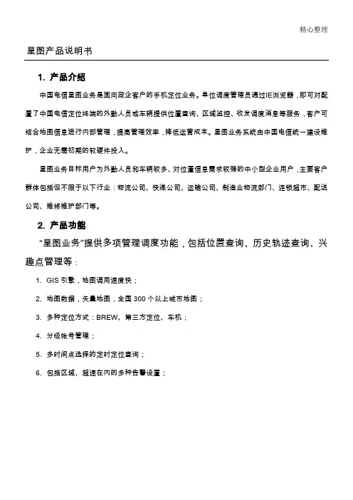
精心整理星图产品说明书1.产品介绍中国电信星图业务是面向政企客户的手机定位业务。
单位调度管理员通过IE浏览器,即可对配置了中国电信定位终端的外勤人员或车辆提供位置查询、区域监控、收发调度消息等服务,客户可结合地图信息进行内部管理,提高管理效率,降低运营成本。
星图业务系统由中国电信统一建设维2.1.2.3.4.5.6.包括区域、超速在内的多种告警设置;3.4.◆公告栏公司内部每日最新消息、事项、通知等公布的窗口。
◆地图运行环境客户端使用星图业务平台的必备软件环境,正常显示页面所使用的软件SUNJRE1.5。
业务平台提供下载路径及方式。
软件下载说明:主页面选择“下载地图运行环境”如下图显示请选择符合操作系统的选项进行下载、安装(请参考下载事例)。
如用户对地图没有进行特定设置,那么每次进入后都将显示为全国地图。
2)位置地图本章主要介绍软件的“位置地图”功能模块,分为位置查询、地物查询、兴趣点、区域设置、历史轨迹和报警信息,以及位置地图的操作工具。
通过本功能模块的使用,可以实现管理者对地域的各种查询,对终端用户的现实、历史行驶轨主页面右侧显示被管理终端列表,以及用户分组情况。
选择被定位终端,用户在终端前“□”打上“√”代表选中用户,同时点击用户前“”会看到用户的最后一次位置信息将显示在地图上。
注意:如果在组名前点击“”那么组中所有终端都将显示在地图上;如在某终端前点击“”则只显示选中的终端。
此时点击“单次定位”将会对管理者所选择的终端实施定位操作,同时页面将显示等待状态。
定位成功、失败,页面都将进行提示,如定位成功,地图上终端相关信息也会随之发生变化定位成功的终端,信息会自动进行更新提示结果:定位成功在定时定位中,可将终端用户定位的时间间隔进行选择,如5分钟、10分钟等多选项;定位时段设置,将选择终端用户的工作日工作时间段内定位,休息日不允许定位。
注意:考虑到由于每次定位终端会产生流量费用,用户不宜将定位时间设置过于密集,建议定位时间间隔选择在30分钟~~~1小时为最佳。
加密通信业务产品说明书
中国电信加密通信业务产品说明书(v1.0)(用于渠道加载)中国电信集团公司目录1、产品描述 (1)2、业务特点 (2)2.1国家商密级认证,语音加密更放心 (2)2.2端到端全程加密,一话一密更安全 (2)2.3专用手机功能强,资料信息可隐藏 (2)2.4手机遗失不用急,远程指令即擦除 (2)3、主要功能 (3)4、服务内容 (4)4.1加密通话功能 (4)4.2信息安全防护功能 (4)5、加密通信终端要求 (6)6、常见问题及故障处理办法 (7)6.1加密通话建立不成功问题 (7)6.1.1 用户发起加密通话后,终端收到错误提示,界面上显示“您没有加密权限”,是什么原因? (7)6.1.2 用户发起加密通话后,终端收到错误提示,界面上显示“对方没有加密权限”,是什么原因? (8)6.1.3 用户发起加密通话后,终端收到错误通知,显示“您在使用非绑定终端”,是什么原因? (8)6.1.4 用户发起加密通话后,终端收到错误通知,显示“对方为非法终端”,是什么原因? (8)6.1.5 用户发起加密通话后,显示“密话请求超时”,是什么原因? (8)6.1.6 用户发起加密通话后,显示“密话请求成功”,但通话双方仍然无法正常通话,是什么原因? (9)6.2终端本地安全设置问题 (10)6.2.1 开机时要求输入安全密码是怎么回事? (10)6.2.2 如何开启终端的安全模式? (10)6.2.3 如何关闭终端的安全模式? (11)6.2.4 如何设置私密联系人? (11)6.3其他问题 (11)6.3.1 需要什么网络环境才能正常使用加密通话业务? (11)6.3.2 忘记进入安全模式的密码怎么办? (11)6.3.3 手机丢失了,但手机上存有隐私信息,怎么办? (12)6.3.4 加密手机如何拨打加密通话。
(12)7、使用流程 (14)7.1建立加密通话流程 (14)7.2退出加密通话流程 (16)7.3异常流程 (16)7.4信息安全保护功能流程 (18)8、使用范围 (23)8.1业务开放范围 (23)8.2业务通达范围 (23)9、使用条件 (24)1、产品描述中国电信加密通信业务基于中国电信广覆盖、大容量的CDMA移动通信网络和安全管理平台,通过中国电信为客户特别定制的,内置国家密码管理局指配加密算法的手机终端,利用商用密码技术和信息安全技术,向客户提供实现商密级的端到端手机话音通信加密功能、手机终端信息保护以及手机终端加密信息的远程擦除等安全服务。
中国电信综合办公产品说明书正式文件word版
中国电信综合办公(网络版)业务产品说明书中国电信政企客户事业部中国电信广州研究院2012年8月目录1 产品简介 (1)1.1 产品定义 (1)1.2 产品特点 (1)1.3产品形态 (2)2 办理及使用条件 (2)2.1 用户办理条件 (2)2.2 用户使用条件 (2)3 使用场景 (3)4 业务服务 (4)4.1 业务办理方式 (4)4.2 客户服务方式 (4)4.3 业务付费方式 (4)5 业务资费 (5)6 促销政策 (5)1产品简介1.1产品定义综合办公(网络版)业务是采用移动互联网技术,基于中国电信的宽带互联网、3G移动通信网络以及集中部署的综合办公(网络版)业务平台,为政企客户提供的在PC机和智能手机等终端使用的融合型办公服务,可满足客户随时随地进行信息共享、交流沟通和协同办公需求。
1.2 产品特点➢融合办公服务采用云平台部署方式,快速实现移动办公服务。
客户无需购买服务器,开通即用,投资小,见效快。
➢资讯及时沟通电子公告、短彩中心、内部邮件等功能,实现信息资讯的及时传递。
➢工作高效协同通讯录、会议管理、协同工作等功能,帮助客户管理、协调企业资源,提高工作效率。
➢日程贴身秘书用户可管理自己的日程安排,并可通过手机及时接收个人日程、会议日程提醒消息。
1.3产品形态图 1 综合办公(网络版)系统架构示意图中国电信集中部署综合办公(网络版)平台,为政企客户提供PC端使用的基础办公和手机端使用的综合办公(网络版)业务。
客户可在具备上网条件下通过PC方式使用各项服务,也可在CDMA网络覆盖范围内通过手机客户端方式使用各项服务。
2办理及使用条件2.1用户办理条件全国范围内使用PC终端和中国电信CDMA手机终端的政府客户、行业客户、中小企业及聚类客户均可申请办理综合办公(网络版)业务。
2.2用户使用条件使用综合办公(网络版)业务需开通宽带上网业务,并且应具备相应的业务终端,包括互联网终端(PC机或其他设备)或手机终端(手机)。
京信天线资料
天线产品单页资料(电信集采版)说明:本册为中国电信集采类产品单页资料,并仅限用于电信客户的集采产品订货。
主要根据《2010年中国电信基站天线及室分天线集采》制定。
天馈事业部天线国内市场部2010年10月目录一、全向天线 (1)型号:OOA-360V11A (1)二、定向单极化天线 (2)型号:ODP-065V17A (2)型号:ODP-065V18A (3)型号:ODP-090V17A (4)三、定向双极化天线 (5)型号:ODP-032R18A (5)型号:ODP-032R21A (6)型号:ODP-065R15A (7)型号:ODP-065R17A (8)型号:ODP-065R18A (9)型号:ODP-090R17A (10)四、双极化电调天线 (11)型号:ODV-032R18A (11)型号:ODV-032R20A (12)型号:ODV-065R15A (13)型号:ODV-065R17A (14)型号:ODV-065R18A (15)型号:ODV-090R17A (16)一、全向天线型号:OOA-360V11A产品描述:CDMA800/360°11dBi全向天线电气性能指标工作频率(MHz)820-880天线增益(dBi)11±1 极化方式垂直极化水平面波瓣宽度(°)360垂直面波瓣宽度(°) 6.5±2 方向图不圆度(dB)±1 电下倾角(°) 3下倾精度(°) ±1 驻波比≤1.4三阶交调(dBm)≤-107 阻抗(Ω)50 功率容量(W)500机械性能指标天线尺寸(mm)3510×Ф52重量(Kg)12.5接头类型7/16阴头环境温度(°C)-55~+70抗风能力工作风速110km/h,极限风速200km/h雷电保护直接接地方向图820~880 MHz方向图水平面垂直面二、定向单极化天线型号:ODP-065V17A产品描述:CDMA800/65°17dBi单极化非电调天线电气性能指标工作频率(MHz)820-880天线增益(dBi)17±1 极化方式垂直极化水平面波瓣宽度(°)65±5垂直面波瓣宽度(°)9±2 前后比(dB)≥28第一上旁瓣抑制(dB)≤-15 下倾精度(°) ±1 驻波比≤1.4三阶交调(dBm)≤-107 电下倾角(°) 0阻抗(Ω)50 功率容量(W)500机械性能指标天线尺寸(mm)1935×265×141重量(Kg)11机械倾角(°)0-12接头类型7/16 Din阴头环境温度(°C)-55~+70抗风能力工作风速110km/h,极限风速200km/h雷电保护直接接地方向图820~880 MHz方向图水平面垂直面产品描述:CDMA800/65°18dBi单极化非电调天线电气性能指标工作频率(MHz)820-880天线增益(dBi)18±1 极化方式垂直极化水平面波瓣宽度(°)65±5 垂直面波瓣宽度(°)7±2 前后比(dB)≥28第一上旁瓣抑制(dB)≤-15 下倾精度(°) ±1 驻波比≤1.4三阶交调(dBm)≤-107电下倾角(°)0/3阻抗(Ω)50 功率容量(W)500机械性能指标天线尺寸(mm)2615×265×141重量(Kg)16.0机械倾角(°)0-8接头类型7/16 Din阴头环境温度(°C)-55~+70抗风能力工作风速110km/h,极限风速200km/h雷电保护直接接地方向图820~880MHz方向图水平面垂直面产品描述:CDMA800/90°17dBi单极化非电调天线电气性能指标工作频率(MHz)820-880天线增益(dBi)16.5±1 极化方式垂直极化水平面波瓣宽度(°)90±8 垂直面波瓣宽度(°)7±2第一上旁瓣抑制(dB) ≤-15 前后比(dB)≥25下倾精度(°) ±1 驻波比≤1.4三阶交调(dBm)≤-107 电下倾角(°) 0/3/6阻抗(Ω)50 功率容量(W)500机械性能指标天线尺寸(mm)2615×265×141重量(Kg)15机械倾角(°) 0-8接头类型7/16 Din阴头环境温度(°C)-55~+70抗风能力工作风速110km/h,极限风速200km/h雷电保护直接接地方向图820~880 MHz方向图水平面垂直面三、定向双极化天线型号:ODP-032R18A描述:CDMA800/32°18dBi双极化定向天线电气性能指标工作频率(MHz)820-880天线增益(dBi)18±1 极化方式±45°交叉极化水平面波瓣宽度(°)32±4垂直面波瓣宽度(°)14±2 前后比(dB)≥30第一上旁瓣抑制(dB) ≥-15交叉极化比(dB)轴向:≥15±15°内:≥10下倾精度(°) ±1驻波比≤1.4隔离度(dB)≥30三阶交调(dBm)≤-107电下倾角(°) 0/3阻抗(Ω)50功率容量(W)500机械性能指标天线尺寸(mm)1315×552×141重量(Kg)20机械倾角(°)0-16接头类型7/16阴头环境温度(°C)-55~+70抗风能力工作风速110km/h,极限风速200km/h雷电保护直流接地方向图820~880 MHz方向图水平面垂直面描述:CDMA800/32°21dBi双极化定向天线电气性能指标工作频率(MHz)820-880天线增益(dBi)20±1 极化方式±45°交叉极化水平面波瓣宽度(°)32±4垂直面波瓣宽度(°)7±2 前后比(dB)≥30第一上旁瓣抑制(dB) ≥-15交叉极化比(dB)轴向:≥15±15°内:≥10下倾精度(°) ±1驻波比≤1.4隔离度(dB)≥30三阶交调(dBm)≤-107电下倾角(°) 0/3阻抗(Ω)50 功率容量(W)500机械性能指标天线尺寸(mm)2615×552×141重量(Kg)37.5机械倾角(°)0-8接头类型7/16阴头环境温度(°C)-55~+70抗风能力工作风速110km/h,极限风速200km/h雷电保护直流接地方向图820~880 MHz方向图水平面垂直面描述:CDMA800/65°15dBi双极化定向天线电气性能指标工作频率(MHz)820-880天线增益(dBi)15±1 极化方式±45°交叉极化水平面波瓣宽度(°)65±5垂直面波瓣宽度(°)14±2 前后比(dB)≥25第一上旁瓣抑制(dB) ≥-15交叉极化比(dB)轴向:≥15±60°内:≥10下倾精度(°) ±1 驻波比≤1.4隔离度(dB)≥30三阶交调(dBm)≤-107 电下倾角(°) 0/3/6 阻抗(Ω)50 功率容量(W)500机械性能指标天线尺寸(mm)1315×265×141 重量(Kg)9.5机械倾角(°) 0-16接头类型7/16阴头环境温度(°C)-55~+70抗风能力工作风速110km/h,极限风速200km/h雷电保护直流接地方向图820~880 MHz方向图水平面垂直面描述:CDMA800/65°17dBi双极化定向天线电气性能指标工作频率(MHz)820-880天线增益(dBi)17±1 极化方式±45°交叉极化水平面波瓣宽度(°)65±5垂直面波瓣宽度(°)9±2 前后比(dB)≥25第一上旁瓣抑制(dB) ≥-15交叉极化比(dB)轴向:≥15±60°内:≥10下倾精度(°) ±1驻波比≤1.4隔离度(dB)≥30三阶交调(dBm)≤-107电下倾角(°) 0/3/6阻抗(Ω)50 功率容量(W)500机械性能指标天线尺寸(mm)1935×265×141重量(Kg)13.8机械倾角(°) 0-12接头类型7/16阴头环境温度(°C)-55~+70抗风能力工作风速110km/h,极限风速200km/h雷电保护直流接地方向图820~880 MHz方向图水平面垂直面描述:CDMA800/65°18dBi双极化定向天线电气性能指标工作频率(MHz)820-880天线增益(dBi)18±1 极化方式±45°交叉极化水平面波瓣宽度(°)65±5垂直面波瓣宽度(°)7±2 前后比(dB)≥25第一上旁瓣抑制(dB) ≥-15交叉极化比(dB)轴向:≥15±60°内:≥10下倾精度(°) ±1 驻波比≤1.4隔离度(dB)≥30三阶交调(dBm)≤-107 电下倾角(°) 0/3/6 阻抗(Ω)50 功率容量(W)500机械性能指标天线尺寸(mm)2615×265×141 重量(Kg)18.5机械倾角(°) 0-8接头类型7/16阴头环境温度(°C)-55~+70抗风能力工作风速110km/h,极限风速200km/h雷电保护直流接地方向图820~880 MHz方向图水平面垂直面描述:CDMA800/90°17dBi双极化定向天线电气性能指标工作频率(MHz)820-880天线增益(dBi)16.5±1 极化方式±45°交叉极化水平面波瓣宽度(°)90±8垂直面波瓣宽度(°)7±2 前后比(dB)≥23第一上旁瓣抑制(dB) ≤-15交叉极化比(dB)轴向:≥15±60°内:≥10下倾精度(°) ±1 驻波比≤1.4隔离度(dB)≥30三阶交调(dBm)≤-107 电下倾角(°) 0/3/6 阻抗(Ω)50 功率容量(W)500机械性能指标天线尺寸(mm)2615×265×141 重量(Kg)31.5机械倾角(°)0-8接头类型7/16阴头环境温度(°C)-55~+70抗风能力工作风速110km/h,极限风速200km/h雷电保护直流接地方向图820~880 MHz方向图水平面垂直面四、双极化电调天线型号:ODV-032R18A产品描述:CDMA800 / 32°18dBi双极化电调天线电气性能指标工作频率(MHz)820~880天线增益(dBi)17.5±1 极化方式±45°交叉极化水平面波瓣宽度(°)32±4垂直面波瓣宽度(°)14±2 前后比(dB)≥30第一上旁瓣抑制(dB)≤-15交叉极化比(dB)轴向:≥15±15°内:≥10下倾精度(°) ±1驻波比≤1.4隔离度(dB)≥30三阶交调(dBm)≤-107电下倾角(°)0-13阻抗(Ω)50功率容量(W)250机械性能指标天线尺寸(mm)1415×560×143重量(Kg)30机械倾角(°)0-16接头类型7/16阴头环境温度(°C)-55~+70抗风能力工作风速110km/h,极限风速200km/h雷电保护直接接地方向图820-880 MHz方向图水平面垂直面产品描述:CDMA800 / 32°20dBi双极化电调天线电气性能指标工作频率(MHz)820~880天线增益(dBi)19.5±1 极化方式±45°交叉极化水平面波瓣宽度(°)32±4垂直面波瓣宽度(°)7±2 前后比(dB)≥30第一上旁瓣抑制(dB)≤-15交叉极化比(dB)轴向:≥15±15°内:≥10下倾精度(°) ±1 驻波比≤1.4隔离度(dB)≥30三阶交调(dBm)≤-107 电下倾角(°)0-10 阻抗(Ω)50 功率容量(W)250机械性能指标天线尺寸(mm)1975×560×143 重量(Kg)41机械倾角(°)0-12接头类型7/16阴头环境温度(°C)-55~+70抗风能力工作风速110km/h,极限风速200km/h雷电保护直接接地方向图820-880 MHz方向图水平面垂直面产品描述:CDMA800 / 65°15dBi双极化电调天线电气性能指标工作频率(MHz)820~880天线增益(dBi)14.5±1 极化方式±45°交叉极化水平面波瓣宽度(°)65±5垂直面波瓣宽度(°)14±2 前后比(dB)≥25第一上旁瓣抑制(dB)≤-15交叉极化比(dB)轴向:≥15±60°内:≥10下倾精度(°) ±1驻波比≤1.4隔离度(dB)≥30三阶交调(dBm)≤-107电下倾角(°)0-14阻抗(Ω)50功率容量(W)250机械性能指标天线尺寸(mm)1415×265×141重量(Kg)12.5机械倾角(°)0-16接头类型7/16阴头环境温度(°C)-55~+70抗风能力工作风速110km/h,极限风速200km/h雷电保护直接接地方向图820-880 MHz方向图水平面垂直面产品描述:CDMA800 / 65°17dBi双极化电调天线电气性能指标工作频率(MHz)820~880天线增益(dBi)16.5±1 极化方式±45°交叉极化水平面波瓣宽度(°)65±5垂直面波瓣宽度(°)9±2 前后比(dB)≥25第一上旁瓣抑制(dB)≤-15交叉极化比(dB)轴向:≥15±60°内:≥10下倾精度(°) ±1驻波比≤1.4隔离度(dB)≥30三阶交调(dBm)≤-107电下倾角(°)0-10阻抗(Ω)50功率容量(W)250机械性能指标天线尺寸(mm)2095×265×141重量(Kg)17.8机械倾角(°)0-12接头类型7/16阴头环境温度(°C)-55~+70抗风能力工作风速110km/h,极限风速200km/h雷电保护直接接地方向图820-880 MHz方向图水平面垂直面产品描述:CDMA800 / 65°18dBi双极化电调天线电气性能指标工作频率(MHz)820~880天线增益(dBi)17.5±1 极化方式±45°交叉极化水平面波瓣宽度(°)65±5垂直面波瓣宽度(°)7±2 前后比(dB)≥25第一上旁瓣抑制(dB)≤-15交叉极化比(dB)轴向:≥15±60°内:≥10下倾精度(°) ±1 驻波比≤1.4隔离度(dB)≥30三阶交调(dBm)≤-107 电下倾角(°)0-7 阻抗(Ω)50 功率容量(W)250机械性能指标天线尺寸(mm)2615×265×141 重量(Kg)21机械倾角(°)0-8接头类型7/16阴头环境温度(°C)-55~+70抗风能力工作风速110km/h,极限风速200km/h雷电保护直接接地方向图820-880 MHz方向图水平面垂直面产品描述:CDMA800 / 90°17dBi双极化电调天线电气性能指标工作频率(MHz)820-880天线增益(dBi)16±1 极化方式±45°交叉极化水平面波瓣宽度(°)90±8垂直面波瓣宽度(°)7±2 前后比(dB)≥23第一上旁瓣抑制(dB)≤-15交叉极化比(dB)轴向:≥15±60°内:≥10下倾精度(°) ±1 驻波比≤1.4隔离度(dB)≥30三阶交调(dBm)≤-107 电下倾角(°)0-7 阻抗(Ω)50 功率容量(W)250机械性能指标天线尺寸(mm)2615×265×141 重量(Kg)27机械倾角(°)0-8接头类型7/16阴头环境温度(°C)-55~+70抗风能力工作风速110km/h,极限风速200km/h雷电保护直接接地方向图820-880 MHz方向图水平面垂直面。
中国电信业务产品手册6(视讯业务)
6.视讯业务6.1.电视电话会议(含国际及港澳台)电视电话会议是用通信线路把两地或多个地点的会议室连接起来,以电视方式召开会议的一种图像通信方式。
两地间的电视电话会议,称为点对点电视电话会议;多个地点间的电视电话会议,称为多点电视电话会议。
电视电话会议的主要特征:是能实时传送与会者的形象、声音以及会议资料、图表和相关实物的图像等;身居不同地点的与会者互相可以闻声见影,如同坐在同一间会议室中开会似的。
电视电话会议的使用已发展到多种应用环境:如政府会议、商务谈判、紧急救援、作战指挥、银行贷款、远程教育、远程医疗等等,取得了巨大社会效益和经济效益。
一、业务描述电视电话会议业务是一种多媒体视能会议型业务。
它采用图像、语音压缩技术,利用电视电话会议通信系统和数字传输电路,在两点或多点间传送活动图像(人物)、语音,应用数据(电子白板、图形)信息形式的通信业务。
二、业务种类1、指定地点式电视电话会议,即用户到局方指定的电视电话会议室组织召开不同速率的电视电话会议。
2、现场式电视电话会议,即局方到用户指定的现场,如授课地点或医院会诊、手术间以及各种会议开幕式的现场等,进行现场转插。
三、业务特征1、画面稳定、清晰,图像逼真,色彩鲜艳。
2、是一种双向电信业务。
3、可同时传递文件、图像、照片和实物的固定图像等信息,实现与对方会场与会人员有研讨与磋商,在效果上完全可以代替现场会议。
四、业务定位适合于召开各种会议、现场交流及其它远程教学、远程医疗、远程股评、声像服务等。
主要用户群为政府机关、医院、大学、企业、公司等大客户和商业客户单位。
五、业务实现电视电话会议通信系统主要由终端设备、传输信道和多点控制设备(MCU)组成,设备包括:摄像机、话筒、编辑导演设备、调音台、电视电话会议终端设备、多点控制设备、图像显示设备、会场扩音及外围设备等。
在全国电视电话会议网还应包括CMMS和监控管理工作站。
六、资费(试行)(一) 国内电视电话会议国内电视电话会议业务的资费包括通话费、预告费、销号手续费。
- 1、下载文档前请自行甄别文档内容的完整性,平台不提供额外的编辑、内容补充、找答案等附加服务。
- 2、"仅部分预览"的文档,不可在线预览部分如存在完整性等问题,可反馈申请退款(可完整预览的文档不适用该条件!)。
- 3、如文档侵犯您的权益,请联系客服反馈,我们会尽快为您处理(人工客服工作时间:9:00-18:30)。
中国电信集团北京市电信有限公司新产品说明书
1
中国电信集团北京市电信有限公司
产品说明书
——话音产品分册
2
目录
第一部分概述 (3)
第二部分 ISDN产品 (4)
第三部分 CENTREX 产品 (9)
第四部分 PBX接入产品 (11)
第五部分选择我们的理由 (13)
3
第一部分概述
北京电信作为北京地区电信市场新进入者, 在网络建设中紧紧依托中国电信覆盖全国31个省( 市、自治区) 强大的、综合的网络优势, 遵循以客户为导向, 快速务实、简洁高效的建网原则, 秉承中国电信网络发展总体规划的要求, 分层次、分业务、综合发展建设包括长途交换机、关口局交换机、市话端局交换机、智能网设备等全新的通信网络, 提供多功能、多层次、个性化的网络应用服务及模拟电话、ISDN电话、拨号上网、智能网等全方位的用户解决方案, 北京电信用户能够与全国各地及世界各个国家、地区的用户进行高品质的信息交流。
网络构成见下图:
4
第二部分 ISDN产品
一、产品简介
ISDN( 综合业务数字网) 由电话综合数字网( IDN) 发展而来, 以迅速、准确、经济、有效的方式将语音和数据通信结合起来, 可为用户提供全新的综合业务。
ISDN是一个全数字的网络, 提供以64kbit/s速率为基础的端到端数字透明连接, 话音、文字、数据和图像等数字信号均可经过ISDN进行传输。
ISDN采用两种标准的用户/网络接口, 即基本速率接口( BRI) 和基群速率接口( PRI) 。
基本速率接口即2B+D( 又称"一线通") , 其中B为64kbit/s速率的数字信道, D为16kbit/s速率的数字信道。
基群速率接口也称一次群速率接口, 即30B+D, B和D均为64kbit/s的数字信道。
B信道主要用于传送用户信息流; D信道主要用于传送电路交换的信令信息。
二、产品应用
( 一) ISDN 2B+D接入方式
1、打电话、发传真: 用户能够同时使用两部电话, 互不干扰。
2、上网: 用户能够64 Kb/s或128Kb/s的速率上网; 在以64 Kb/s速率上网的时候, 用户还可使用另一个部电话进行通信。
5。