短波天线设计手册
超短波电台的天线设计和布局
超短波电台的天线设计和布局超短波(VHF)电台天线设计和布局是确保无线电通信质量的重要因素之一。
在进行超短波电台天线设计和布局时,需要考虑一系列因素,包括频率选择、天线类型选择、天线高度、天线方向等。
本文将介绍超短波电台天线设计和布局的相关要点和步骤。
首先,选择适当的频率范围对于超短波电台天线设计和布局来说至关重要。
超短波频率范围通常为30 MHz至300 MHz。
在选择频率时,需要考虑频段内的电台竞争、电波传播特性以及业务需求等因素。
第二步是选择合适的天线类型。
超短波电台天线常见的类型包括单极化垂直天线、水平偶极子天线、定向天线等。
不同的天线类型适用于不同的应用场景。
例如,单极化垂直天线适用于广播和移动通信系统,水平偶极子天线适用于互联网数据传输,而定向天线适用于远距离通信。
天线高度也是超短波电台天线设计和布局的重要考虑因素之一。
天线高度的选择应该综合考虑电波传播特性、地形、建筑物等因素。
较高的天线高度通常可以提高信号覆盖范围和传输距离,但在具体应用中也需要权衡成本和实际需求。
天线的方向性也是需要关注的因素之一。
根据业务需求和覆盖范围需求,选择合适的天线方向性,例如全向天线(Omni)或定向天线(Directional)。
全向天线能够在水平方向等角度范围内均匀地辐射或接收信号,适用于广播和移动通信系统。
而定向天线则能将信号集中在特定方向,适用于远距离通信和数据传输。
在进行布局时,应该考虑附近环境的限制,避免与建筑物、高压线、其他天线等物体相互干扰。
尽可能选择较为开阔的场地,以提高信号覆盖范围和减少大楼和地形对信号的影响。
此外,合理的天线间距和天线高度差也是布局的关键环节。
对于多个天线并存的情况,需要避免天线之间的互相干扰。
根据天线之间的主辐射角度和方向性,确定合适的天线间距和高度差,以防止相互之间的干扰。
在实际布局过程中,还需要考虑信号接收器和发射器之间的连接线缆。
合理选择低损耗的传输线缆和合适的连接方式,以减少信号损耗和保证良好的连接质量。
短波通信天线系统的优化与设计

短波通信天线系统的优化与设计第一章引言短波通信作为一种重要的无线通信技术,在现代社会中扮演着重要角色。
短波信号可以在大范围内传输,并能克服障碍物的影响,具有抗干扰能力强的优势。
短波通信的天线系统在优化设计中起着至关重要的作用。
本文将重点探讨短波通信天线系统的优化与设计方法及其在实际应用中的意义。
第二章短波通信天线系统的基本原理短波通信天线系统的基本原理包括传输原理和天线系统原理两个方面。
传输原理主要包括调制解调、编码解码和调频等相关内容。
天线系统原理主要涉及天线的基本参数、辐射场图和天线阻抗匹配等。
第三章短波通信天线系统的优化方法3.1 天线形式的优化为了提高短波通信天线系统的性能,可以通过优化天线的形式进行改进。
例如,采用多元天线系统,能够提高天线系统的方向性和增益。
基于相控阵技术的天线系统可以实现波束的形成和指向性的调整,提高信号的传输质量。
此外,近年来,人们也开始研究应用人工智能算法来优化天线的形式,提高天线对信号的接收和发射能力。
3.2 天线位置的优化天线的位置选择对短波通信天线系统的信号传输质量有着重要影响。
合理选择天线的位置和布局,能够减少信号的传输损耗和多径效应的影响。
通过合适的方位角和仰角选择,可以将信号的传输方向调整到最有效的位置。
此外,考虑到环境因素的影响,也需要进行合理的天线高度选择,以最大限度减少天线系统对周围环境的影响。
3.3 天线参数的优化短波通信天线系统的重要参数包括增益、辐射方向图、输入阻抗等。
通过优化这些参数,可以提高天线系统的性能。
增益是衡量天线系统接收和发射能力的重要指标,可以通过改变天线的尺寸和形状来提高增益。
同时,辐射方向图的优化可以使天线系统在特定方向上具有更好的指向性,减少信号的传输损耗。
此外,更好的输入阻抗匹配能够减少信号的反射损耗和回波影响。
第四章短波通信天线系统的设计注意事项4.1 考虑频段要求短波通信天线系统的设计要根据实际应用频段的要求进行。
短波天线设计与性能研究
短波天线设计与性能研究一、引言随着无线电通信技术的不断进步,短波通信作为一种广泛使用的通信方式,被越来越多的人所青睐。
在短波通信中,天线作为直接与空气接触的设备,对通信距离和信号传输质量有着至关重要的影响。
因此,短波天线的设计和性能研究愈发受到人们的关注。
本文将探讨短波天线的设计方法、常见天线类型、性能指标以及相应的优化方法。
二、天线设计方法在短波天线的设计中,需要考虑天线的尺寸、形状以及电学参数等多个方面。
以下是一些常见的天线设计方法:1. 经验法经验法是指基于实验数据和经验公式来确定天线的尺寸和形状。
这种方法在早期应用较为广泛,但是由于其缺乏理论算法支持,精度有限,已逐步被其他设计方法取代。
2. 电磁仿真法电磁仿真法是指利用计算机软件模拟天线在电磁场中的运行情况,预测天线的性能指标。
常见的电磁仿真软件有CST、HFSS等。
这种方法具有高精度、快速、可重复性好等优点。
3. 优化法优化法是指通过对天线的几何尺寸和电学参数进行多次修改和优化,使得天线的性能指标达到最优。
常见的优化算法有遗传算法、粒子群算法等。
这种方法可以大幅提高天线的性能。
三、常见短波天线类型在短波通信中,常见的天线类型主要有以下几种:1. 垂直天线垂直天线也称为垂直偶极天线,具有较好的全向性,适合于近距离通信和轮廓线比较平坦的地形。
常见的垂直天线有垂直半波长天线、垂直1/4波长天线等。
2. 水平天线水平天线也称为水平偶极天线,具有较好的指向性和远距离通信能力,适合用于中远距离通信。
常见的水平天线有水平全波长天线、水平半波长天线等。
3. 组合天线组合天线是指将不同类型的天线组合在一起使用,以达到最佳的通信效果。
常见的组合天线包括水平天线和垂直天线结合的单元天线、水平天线与垂直天线叠置的交替天线等。
四、常见短波天线性能指标及优化方法天线的性能指标包括增益、驻波比、方向性、极化等多个方面。
以下将具体讲述常见的指标和相应的优化方法:1. 增益增益是指天线将收到的无线电信号转换成有用信号的能力。
天线手册(Antenna Handbook)概要
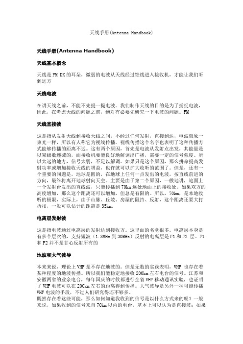
天线手册(Antenna Handbook)天线手册(Antenna Handbook)天线基本概念天线是FM DX的耳朵,微弱的电波从天线经过馈线进入接收机,才能让我们听到远方天线电波在讲天线之前,不能不先提一提电波。
我们制作天线的目的是为了捕捉电波,因此,在考虑天线的问题之前,绝对有必要先研究一下电波的问题。
FM天线直接波这是指从发射天线到接收天线之间,不经过任何发射,直接到达,电波就象一束光一样,所以有人称它为视线传播。
视线传播这个名字也表明了这种传播方式能够传播的距离不远。
这有两个原因,首先是电波从发射点出发,其能量是以幂级数递减的,而接收机要能良好地解调出广播,需要一定的信号强度。
所以太远的地方,信号太弱,不足以解调。
如果只是这个原因,那么拼命提高发射功率或增加接收天线的增益,也许就可以扩大收听的范围了。
但是,还有一个重要的问题是,地球是圆的,在地球上任何一点发出的电波,按直线前进的方向,最终将离开地球射向天空。
主要是由于第二个原因,一般地讲,地面上一个发射台发出的直线波,只能传播到70km远处地面上的接收处。
如果双方的高度增加,那么这个距离还可以增加,但总是有限的。
所以,70km,是本地收听的极限,实际上,由于山脉、丘陵、房屋的阻挡、反射,这个距离还要大打折扣,一般可以估计的距离是35km。
电离层发射波这是指电波通过电离层的发射达到接收方。
这里面的名堂很多。
电离层本身是有多个层次的,支持短波(1.8MHz到30MHz)反射的电离层是F1和F2 层。
F1和F2并不是甘心反射所有的地波和大气波导本来来说,理论上VHF是不存在地波的。
但是无数的实践表明,VHF 也存在着某种程度的地波传播。
所以我们能稳定地接收200km左右电台的信号。
江苏和安徽两省的业余电台,每年国庆的时候都进行全省VHF移动通讯实验,也证明了VHF电波可以在200km左右的距离得到传播。
大气波导是另外一种可能传播VHF电波的手段,不过人们研究得还不够多。
自制室内有源短波环状天线

自制室内有源短波环状天线
用身边的废旧物制作一台短波有源环状天线.经试验.短波段2.8-16mhz灵敏度有明显提升.具有方向感.抗杂良好.声音清晰.抗扰好.似乎感觉由他把播音员与收听者拉近了距离.非常适合于中、高端质地优良的收音机...以下图片说明制作过程:仅供爱好者参考.不妥之处.请校正!
一、在直径8MM铝管穿入1MM塑包铜引线.环径为280MM.将引线与6.35MM插头(旧的话筒插头)焊接相连.铝管两个端口固定在废弃的电源适配器塑盒合口处.并用AB胶浸固.以上需在同时间组装。
一气呵成。
二、用一只旧款电视天线放大器塑盒.保留船型电源开关和红色的Led.其余全部拆除。
三、将电路安装在废弃VCD的射频盒内.配上6.35MM插座.360P空联与天线放大器塑盒固定…等等。
四、喷上个人所喜爱的颜色.
五、调试中使用的几个环…
六、完工之后.在短波2.8-16mhz.能获得享受级别。
MA-8040V短波天线手册侧

Assembly and Installation InstructionsCushcraft MA8040V Dual-Band Vertical Antenna 80 – 40 Meter Vertical Monopole Antenna956358_GF_AAAppendix 1: How to make a Current-Choke Balun using a Toroid Form:A current-choke style balun may be used to prevent the antenna’s feedline from interacting with the antenna and radial system. Best SWR performance was obtained with a choke similar to the one shown hereinstalled at the antenna base.MA8040V Specifications:Frequency Coverage:3.5-4.0 MHz, 7.0–7.3 MHzImpedance:50-OhmsSWR: 1.1:1 typical at resonanceBandwidth (2:1 SWR) 100 kHz on 80/75 meters, 300 kHz on 40 meters Height: 23-27 feet (adjustable for 3.5 – 4.0 MHz coverage)Weight:9.0 LB (4.1 kg.)Typical Gain:0 dBi @ 3.5 MHz, 2 dBi @ 7 MHzGround Radials:Eight recommended (4 x 65’, 4 x 35’)Limited Warranty:Cushcraft Corporation, 48 Perimeter Road, Manchester, New Hampshire 03103, warrants to the original consumer purchaser for one year from date of purchase that each Cushcraft antenna is free of defects in material or workmanship. If, in the judgment of Cushcraft, any such antenna is defective, then Cushcraft Corporation will, at its option, repair or replace the antennas at its expense within thirty days of the date the antenna is returned (at purchaser’s expense) to Cushcraft or one of its authorized representatives. This warranty is in lieu of all other expressed warranties, and implied warranty is limited in duration to one year. Cushcraft Corporation shall not be liable for any incidental or consequential damages which may result from a defect. Some states do not allow limitations on how long an implied warranty lasts or exclusions orlimitations of incidental or consequential damages, so the above limitation may not apply to you. This warranty gives you specific legal rights and you may also have other rights which vary from state to state. This warranty does not extend to any products which have been subject to misuse, neglect, accident, or improper installation. Any repairs or alterations outside of the Cushcraft factory will nullify this warranty.48 Perimeter RoadManchester, NH 03103603-627-7877 FAX 603-627-1764SPECIFICATIONS SUBJECT TO CHANGE WITHOUT NOTICERG-58 for low power or RG-303 for high power5977003801FT240-73Amidon AssociatesFair-RIte 2.4" OD Toroid Core 12 - 14 Turns coax on UseorMA8040V General Description:The MA8040V is a self-supporting monopole-style vertical for 80 and 40 meters. Parallel L/C resonators provide automatic bandswitching with full-band coverage from 7.0 – 7.3 MHz and adjustable tuning to any 100-kHz segment between 3.5 – 4.0 MHz.Heavy-duty loading coils and resilient stainless capacitive hats deliver high efficiency while handling up to 1500-Watts PEP.Designed especially for DX operation, the radiation pattern provides a low launch angle to favor distant contacts and a deep overhead null to cancel unwanted local QRM. The MA8040V weighs only 9 pounds for safe handling and ease of installation.Parts List: Before assembling, read manual thoroughly and check contents against the parts list below:X Quan. Part # Description[ ]180100095/8” x 8-32 screw[ ]10100401-1/4” x 8-32 screw[ ]30101231-1/2” x 8-32 screw[ ]20102311-3/4” x 8-32 screw[ ]40101202” x 8-32 screw[ ]10147642-1/4” x 8-32 screw (Philips Head)[ ]45010011Hex nut, 8-32[ ]27011941Split lock washer, #8[ ]4360941Flat aluminum spacer washer, #10[ ]2320056Aluminum spacer, 1/4” x 5/16” OD[ ]10100449Star-locking solder lug[ ]2194173Small 90-degree aluminum bracket[ ]41056301/2” x 1/4” OD loading coil standoff spacer.[ ]12056249Vinyl radial-rod cap[ ]10551051/4” ID black vinyl tip cap[ ]4030412Large worm clamp[ ]3030407Small worm clamp[ ]1MA8040VJ1Formed jumper wire[ ] 1902428Braid strap[ ] 11563361/2” ID tuning stub bushing[ ]1MA8040VCA280-meter loading coil assembly[ ]1MA8040VCA140-meter loading coil assembly[ ] 4226442Stainless steel radial-rod stock, 0.1” X 25”[ ]8226443Stainless steel radial-rod stock, 0.1” X 31”[ ]31941748-hole radial ring[ ]2196242Upper radial ring support bracket[ ]2195393Lower radial clip[ ] 1196230Lower radial clip support bracket[ ]1290326Danger label[ ]1296357MA8040V Product Label[ ]1096359Radial wire kit (400’ spool, #18 solid enamel)[ ]1126228Fiberglass resonator support, 1” OD x 29-1/2’” tube[ ]1126241Fiberglass base insulator, 1.25” OD x 16” tube[ ]1MA8040VBAT Aluminum base radiator section-1, 1-3/8” OD x 36” tube[ ]1MA8040VBB Aluminum radiator splice section, 1-1/4” x 12” tube[ ]1MA8040VBC Aluminum radiator section-2, 1-3/8” x 72” tube[ ]1MA8040VBD Aluminum radiator section-3, 1-1/4” x 72” tube[ ]1MA8040VBE Aluminum radiator section-4, 1-1/8” x 72” tube[ ]1MA8040VBAB Aluminum base support section, 1-3/8” x 12” tube[ ]1MA8040VBF Aluminum resonator stub section-1, 1/2” OD x 23-7/8” tube[ ]1MA8040VBG Aluminum resonator stub section-2, 3/8” OD x 23-7/8” tube[ ]1MA8040VBH Aluminum resonator stub section-3, 1/4” OD x 23-7/8” aluminum rod Step-16: Tune-up and testUse a handheld SWR analyzer or transceiver with SWR meter to set up the MA8040V. If your radio has an auto tuner, turn it off while making adjustments. To lower the antenna for top-section adjustments without disrupting ground radials, loosen worm clamp and separate sections 1 and 2 (see Figure-16below).[ ] 80meters: Adjust top section for minimum SWR at center of desired 100-kHz segment.Tuning may vary with different ground conditions and depending on proximity of other conductors. For best SWR at low end of band, clamp hat rods for maximum extension from the radial ring to increase hat diameter (refer back to Step-10Fig-10). This setting lowers tuning range by 50 kHz. For best SWR performance at top of band or MARS coverage, set hat rods for minimum extensionand remove one rod. Removing a rod increases range by 100- kHz). Use Graph-1below as a guideline for your initial resonator setting:Frequency MHzResonatorLengthMinimum Hat-Rod ExtensionMaximum Hat-Rod ExtensionMinimum Extension, 1 Rod RemovedGraph-1: Suggested 80-meter Resonator Settings[ ] 40meters:SWR should measures 2:1 or less across the entire 40-meter band with the 25” hat-rods provided. Tuning the 80-meter resonator will have little or no impact on 40-meter tuning.Avoid tuning the MA8040V in wet weather—water droplets on coils and radiator surfaces will lower operating frequency artificially and result in mistuning.Assembly Instructions- MA8040VStep 1: Using the following items, install aluminum tubes on base insulator.1 MA8040VBAB 12” x 1-3/8” OD aluminum base section 1 MA8040VBAT 36” x 1-3/8” OD aluminum antenna section #1 1 126241 16” x 1-1/4” OD fiberglass base insulator2 010231 1-3/4” x 8-32 screw 2 010011 #8 nut 2 011941 #8 lock washer[ ] Identify lower end of base insulator (two through-holes, 90-degrees offset). [ ] Install slotted end of 12” base tube on insulator and align screw holes. [ ] Insert 1-3/4” screw at A . Secure with lock washer and nut.[ ] Install 36” antenna section #1 over other end of insulator and align screw hole. [ ] Insert a 1-3/4” screw at B . Secure with a lock washer and nut.InsulatorAntenna TubeBATStep-2: Using the following items, assemble and install ground-radial attachment ring. 1 014764 2-1/4” x 8-32 SS screw 8 010009 5/8” x 8-32 SS screw 9 011941 #8 lock w asher 9 010011 #8 nut 2 320056 1/4” spacer 1 194174 8-hole r adial ring 2 194173 Small 90-degree aluminum bracket[ ] Find the 2-1/4” screw, two small 90° angle brackets, and two 1/4” spacers. [ ] Note that 90° angle brackets have unequal sides . Identify short side of each. [ ] Install bracket (short side) and a 1/4” spacer on the 2-1/4” screw. [ ] Insert screw through base tube as shown at A .[ ] Install other 1/4” spacer and bracket (short side) on protruding end of screw.[ ] Position brackets as shown and secure in place firmly using lock washer and nut.[ ] Insert 5/8” screws through angle brackets and place radial ring on top (B ). [ ] Secure radial ring in place with lock washers and nuts (2 places)Step 14: Install Antenna on Base Section1030412Large Worm clamp[ ] Slip a large worm clamp on top of base section, positioning below split in tube (see Figure-14).[ ] Carefully raise vertical radiator and insert splice tube into the base section.[ ] Slide worm clamp into position over split in tube and tighten in place.Handling Precautions:During installation,always use the buddy system to avoid injury and prevent antenna damage. Also, neverFigure-14: Raising AntennaStep-15: Connect feedline to antenna base.2 100449 Solder lugPrepare coax, as shown in Figure-15. Attach center conductor to main radiator and shield to ground radialring using solder lugs. For best weather protection, flood braid with a weather-resistant liquid sealant suchas Liquid Tape™. This will prevent water from entering the coax and wicking along the shield. Coil severalturns of coax next to the antenna base or install a choke balun at the feed point (see Appendix-1 for choke-balun fabrication instructions). Feedline leading to station may be buried between radials.1-3/4"Cable PigtailStep-3: Using the following items, assemble upper (80-meter) capacitive-hat support ring:2 1941748-hole radial ring2 196242 Upper radial-ring support bracket 8 010009 5/8” x 8-32 screw2 360941 #10 aluminum spacer washer8 011941 #8 lock washer8010011#8 nut[ ] Locate two radial rings and place together so cupped grooves oppose. [ ] Install two 5/8” screws from top side, as shown. [ ] From bottom side, install a #10 spacer washer and support bracket on each screw.[ ] Secure assembly using lock washers and nuts (finger-tighten only for now).[ ] Install six 5/8” screws in remaining holes, secure with lock washers and nuts.[ ] Set assembly aside for later installation.#10 aluminum washer (x2)radial ring (x2)5/8" x 8-32 (x6)lockwasher (x6)Figure-3: Assembly Detail, Upper HatStep-4:Using the following items, assemble lower (40-meter) capacitive hat radial clip.2195393Lower 4-radial clip1 196230 Lower radial clip support bracket2 360941 #10 aluminum spacer washer2010009 5/8” x 8-32 screw2011941 #8 lock washer2010011#8 nut[ ] Locate two radial clips and place together so cupped grooves oppose.[ ] Insert two 5/8” screws from top side, as shown.[ ] Install a spacer washer from bottom side on each screw.[ ] Insert both screws down through the radial-clip bracket, as shown. [ ] Secure bracket in place with lock washers and nuts (finger-tighten only).[ ] Set assembly aside for later installation.radial clip (2)spacer washer (2)Figure-4: Lower Radial Clip AssemblyConnecting Radials to Base Radial RingRestricted Space PatternFigure-12B: Recommended radial-wire layoutImportant Note:More than the prescribed number of radials may be installed on the MA8040V at your optionin order to optimize radiation efficiency. However, note that as radials are added, SWR may eventually increase to an unacceptable level as driving resistance drops progressively further below 50Ohms. Use the best compromise for your operating location.Step-13: Install Resonator on Vertical Radiator1 010123 1-1/2” x 8-32 screw1010011#8 nut[ ] Slip the resonator tube inside the top of 1-1/8” radiator tube BE (Figure-13).[ ] Position the contact lugs over the tubing mounting holes, as shown.[ ] Using a 1-1/2” screw and 8-32 nut, secure resonator tube and coil wires in place. Tighten securely.Figure-13: Resonator Installation DetailStep-5: Using the following items, install resonator loading coils.1 12622824” Fiberglass resonator support tube1 MA8040VCA280-meter loading coil1 MA8040VCA1 40-meter loading coil4 105630 Loading coil standoff spacer4 010120 2” x 8-32 screw 8010011 #8 nut [ ] On the insulator tube, identify the four coil-mount hole locations.[ ] Install a 2” screw in each coil-mount hole and secure with a nut. [ ] Install a spacer on each of the two 40-meter coil mounts at locations A , B . [ ] Find the 40-meter coil and identify the end with screw and longer lead.[ ] Orienting as shown at E , slide coil over tube and drop onto mounts. Secure with nuts.[ ] Find 80-meter loading coil and identify end with longer lead (F).[ ] Repeat the above procedure for the 80-meter coil at C , D .locationlocationFigure-5: Loading Coil MountingStep-6:Using the following parts, install lower radial clip and jumper wire.1----------Radial clip assembly (as completed in Step-4)1 MA8040VJ1 80-meter resonator jumper wire 1 010040 1-1/4” x 8-32 screw 1 010123 1-1/2” x 8-32 screw 2010011 #8 nut[ ] At A , use a 1-1/2” screw to install coil lug and 40-Meter radial-clip assembly, as shown.[ ] Secure in place with a nut.[ ] At B , install 1-1/4” screw through 80-Meter coil lead and insert through insulator tube. [ ] On opposite side, install one end of jumper wire and secure with nut.[ ] Position other end of jumper as shown at C . These leads will be attached to the antenna later on.bags of pre-mixed concrete are inexpensive and readily available at most major hardware outlets.Sink tube a minimum of four feet and plumb with a level to ensure a straight vertical mount. When installation is completed, use a hacksaw to remove damaged or un-needed exposed conduit. When sinking conduit in concrete, do not allow tube to fill within 10” of top. If tube fills above this level, the antenna’s base assembly cannot drop inside.Figure-11A: Suggested base supports.MA8040V base tube may be set into 1-1/2” thin-wall conduit or clamped to side of post (Figure-10B).Notch support pipe to prevent antenna from rotating in baseSuggested mounting techniquesStep-12: Install ground-radials1096359 400’ spool of #18 enameled radial wire8 100449Solder LugInstallation Tips:When possible, bury wire 2-4 inches below surface. Forlawns, split turf with edger, insertwire, then press turf back together. For rocky or wooded terrain, cover with topsoil, tamp down, and addground-cover. Meander wire to skirt obstructions such as rocks and trees. If unable to extend ’65 radials, we recommend cutting and installing twelve 33-foot radials as an alternative ground system.[ ] Install the antenna base assembly on its mount (see Figure-12A ).[ ] Unroll, measure, and cut four 35-foot lengths of wire. Roll up and set aside. [ ] Unroll, measure, and cut four 65-foot lengths of wire. Roll up and set aside. [ ] At one end of each wire, remove enamel insulation and install a solder lug.[ ] Connect radials to base-section radial ring, alternating long and short lengths.[ ] Unroll and install each, creating the star pattern shown in Figure-12B .Step-7: Using the following items, complete assembly of upper resonator.1 ----------80-meter radial ring assembly (as completed in Step-3) 1MA8040VBF1/2” OD x 24” resonator stub1MA8040VBG3/8” OD x 24” resonator stub1MA8040VBH1/4” OD x 24” resonator stub (solid rod)10551051/4” vinyl end cap3030407 Small worm clamp10101231-1/2” x 8-32 screw1902428Braid strap11563361/2” ID 80-meter resonator-stub bushing[ ] Insert 1/2” tube (BF) into the 1/2” ID bushing and align screw holes(A).[ ] Install the bushing and tube inside fiberglass resonator tube. Align all screw holes (B).[ ] Slide 80-meter radial-ring assembly over outside of resonator tube, position with screw holes aligned (C). [ ] Install 1-1/2”screw at (D)and capture coil-lead lug at bottom. Secure with nut and tighten firmly.[ ] Find braid strap and nip eye off one end, as shown at (E).[ ] Using existing hardware on radial ring, attach braid strap at (F) and secure in place.[ ] Install small worm clamp on resonator tube and use to secure nipped end of braid.[ ] Install small worm clamp on end of 1/2” tube BF, insert 3/8” tube BG and secure (G).[ ] Install small worm clamp on end of 3/8” tube BG, insert 1/4” rod BH and secure (H).[ ] Slip 1/4” vinyl tip cap on end of 1/4” rod BH at (I). Resonator will be set to length later on.Figure-7: Upper Resonator( 80-meter) Assembly Step-8: Using the following items, assemble antenna radiator.1MA8040VBB Aluminum splice tube, 12” x 1-1/4”1MA8040VBC Aluminum radiator section-2, 72” x 1-3/8” OD1MA8040VBD Aluminum radiator section-3, 72” x 1-1/4” OD1 MA8040VBE Aluminum radiator section-4, 72” x 1-1/8” OD3030412Large Worm clamp[ ] Place a worm clamp on one end of tube BC (72” x 1-3/8”).[ ] Find 12” x 1-1/4” splice tube BB. Measure off 6” and mark.[ ] Insert BB6” inside BC,secure with worm clamp.[ ] Place a worm clamp at far end of tube BC.[ ] Find 72” x 1-1/4” tube BD and locate the un-slotted end. Measure off 6” and mark. [ ] Insert BD6” inside BC and secure with clamp.[ ] Place a worm clamp on slotted end of BD.[ ] Find 72” x 1-1/8” tube BE and locate the un-slotted end. Measure off 6” and mark. [ ] Insert BE6” into BD and secure with clamp.tubeFigure-8: Vertical Radiator Assembly Step-9:Using the following items, install 40-meter capacitive-hat rods.1----------Pre-assembled resonator section (from Step-7)4226442Radial rod stock, 0.1” x25”4056249Vinyl end caps[ ] Loosen the 40-meter radial-clip hardware.[ ] Install the four 25” rods, one in each clip opening. Tighten securely to capture all four rods.[ ] Install a plastic end cap on each protruding rod end (lubricate with soap, as needed, to install).Install pla sFigure-9: Installing 40-meter Radial RodsStep-10: Using the following items, install 80-meter rods on resonator assembly.8226443Radial-rod, 0.1” x 31”8056249 Vinyl end cap[ ] Install a vinyl end cap on one end of each rod (lubricate with soap, as needed, to install).[ ] Loosen radial-ring hardware and install rods, as shown in Figure-10.[ ] Use maximum extension for best low-end tuning, minimum for best high-end tuning. Tighten hardware.Figure-10: Inserting and adjusting radial rodsStep-11: Construct a base support.Important Installation Site Safety Considerations:1.No part of the antenna should contact overhead tree branches or foliage.2.Antenna must be well clear of all power wires if accidentally toppled in any direction.3.RF-energized surfaces must be inaccessible to accidental contact by people or pets.4.RF exposure of humans in nearby occupied areas should not exceed FCC guidelines.5.Other feedlines, masts, towers,etc. must be sufficiently far away to avoid detuning.The MA8040V requires a stable base support(owner supplied). Any suitable support may be used, but the antenna was especially designed to drop into 1-1/2” OD thin-wall steel galvanized conduit. This tubing may be either driven into the ground or set into a posthole and captured in concrete (Figure-11A). Conduit and。
短波天线的制作范文
短波天线的制作范文
短波天线是无线电通信的重要组成部分,它能够接收和发送短波信号。
制作一根性能良好的短波天线可以提高通信质量和信号传输距离。
下面将
介绍一种制作短波天线的方法。
接下来,我们将进行下述步骤来制作短波天线:
1.挑选合适的地点:在选择短波天线安装的地点时,要尽量选择无遮
挡的高处,以确保信号传输的稳定和远距离。
2.测量电缆长度:根据实际情况,将电缆剪成合适长度。
一般来说,
短波天线的长度应该在10到100米之间。
3.剥去电缆绝缘层:使用电线剥皮器或刀片,将电缆的绝缘层刮除一
段长度,暴露出内部的电线(一根或多根)。
4.制作接地线:将一根细铁丝固定在电缆的一端,然后将其插入土壤
中作为接地线,以便排除干扰和保证天线效果。
5.安装指向性天线:将指向性天线通过塑料夹子固定在适当位置上,
确保天线可以与电缆连接。
6.安装电缆:确保电缆与天线牢固连接,使用电缆夹等工具来保持稳固。
7.调整天线方向:根据实际需求,调整天线指向,以获得更好的信号
接收和传输效果。
9.测试:完成天线制作后,使用无线电设备向天线发送信号,检查接
收效果和传输距离。
通过以上步骤,我们可以制作出一根性能良好的短波天线。
然而,这只是一种基本的制作方法,实际情况可能会因地点、设备等因素而有所不同。
因此,在制作短波天线之前,需要充分了解相关知识和技术,并根据实际情况进行调整和改进。
总之,短波天线的制作可以提高无线电通信的质量和距离,为使用者提供更好的体验。
希望以上介绍能够对您在制作短波天线时有一些帮助和指导。
机载短波天线设计
机载短波天线设计艾夏史小卫崔昌云(西安电子科技大学天线与微波技术国家重点实验室,西安,710071)aixia.xidian@摘要:短波天线作为短波通信的前端,在短波通信系统中有着举足轻重的地位。
机载天线作为飞机导航、通信等系统的重要组件,实现远距离通信主要依靠机载短波天线。
新型复合材料的使用以及飞机尺寸的增大,是国际飞机发展的潮流。
本文针对这一问题,对新型复合材料大飞机机载隐蔽式短波天线做了初步设计,该设计以现有回线天线为蓝本,进行了改进,使其适应新的使用条件,对机载短波天线的设计具有指导意义。
关键词:短波天线,回线天线,方向图,输入阻抗The design of hf airbone antennaAI xia, SHI xiaowei, Cui changyun(National Key Laboratory of Antennas and Microwave Technology, Xidian Univ., Xi’an,710071)Abstract:As the front-end of an HF communication system, HF antenna plays an important role in HF communication system. As the important modules of aircraft navigation and correspondence systems ,the remote distance communication mainly depends on the airborne HF antenna. The use of new materials and larger size of aircraft is international issues.In this paper, we design an HF antenna which is on a large aircraft whose surface is new composite material. The design is based on the existing loop antenna, and is improved to adapt to the new conditions that use new materials and larger size of aircraft.Keywords: HF antenna;loop antenna;Radiation Pattern;input impedance1 引言随着国内航空航天事业的飞速发展,对机载设备的要求也越来越高。
R-6000短波天线手册
LOCATION Although the R6000 will operate in almost any location, it will perform best if it is mounted vertically and located in the clear away from surrounding objects such as buildings, trees, power lines, towers, guy wires, antennas and metallic objects. The R6000 should not be attached to a ground radial system. Failure to heed these points will possibly degrade performance, detune the antenna and increase VSWR.
ADJUSTMENT The dimensions in Chart A normally allow proper operation on all the bands. However, some variations may occur from one location to another. Adjustments must be made from the bottom of the antenna to the top. Adjusting the antenna from top to bottom will not work. This is because the settings at the top are severely affected by the adjustments at the bottom.
短波电台天线架设
目
CONTENCT
录
• 引言 • 短波电台天线基础知识 • 短波电台天线架设步骤 • 短波电台天线架设的注意事项 • 案例分析 • 结论
01
引言
目的和背景
短波电台天线架设的主要目的是为了实现无线电通信,特别是在 长距离通信和广播中。
在军事、民用和商业领域,短波电台天线架设都发挥着重要的作 用,特别是在没有其他通信手段可用的情况下。
绿色环保
在可持续发展理念的推动下,未来短波电台天线架设将更 加注重绿色环保,减少对环境的影响,实现与自然环境的 和谐共存。
智能化发展
随着人工智能和物联网技术的普及,未来短波电台天线架 设将朝着智能化方向发展,实现自动化监测、远程控制和 智能管理等功能,提高工作效率和安全性。
THANK YOU
感谢聆听
案例二
某短波电台天线架设项目在运行过程中出现了设备故障和维修困难的问题,原因 是设备选型不当、质量不过关以及缺乏有效的维护保养措施。
案例总结与启示
成功案例的共同点在于充分考虑了实际情况和需求,采用了先进的技术和合理的方案,确保了天线架 设的成功和高效。
问题案例的教训在于未能全面评估和应对各种风险因素,缺乏有效的维护保养措施,导致项目实施和运 行过程中出现了各种问题。
100%
避免干扰其他设施
在架设天线时,应尽量避免与其 他通信设施、电力设施等产生干 扰,如可能,应保持一定距离。
80%
做好防雷措施
天线应安装避雷针或其他防雷设 施,以避免雷击对设备和人员造 成伤害。
环境因素考虑
考虑地形影响
在架设天线时,应充分考虑地 形对信号传输的影响,尽量选 择地势较高、无遮挡物的位置 。
极化方式