Incommensurate phases in ferromagnetic spin-chains with weak antiferromagnetic interchain i
Quantum spin liquid emerging in 2D correlated Dirac fermions

The Symmetry of Multiferroics
arXiv:cond-mat/0610241v3 [cond-mat.mtrl-sci] 12 Oct 2006
This paper represents a detailed instruction manual for constructing the Landau expansion for magnetoelectric coupling in incommensurate ferroelectric magnets. The first step is to describe the magnetic ordering in terms of symmetry adapted coordinates which serve as complex valued magnetic order parameters whose transformation properties are displayed. In so doing we use the previously proposed technique to exploit inversion symmetry, since this symmetry had been universally overlooked. Having order parameters of known symmetry which describe the magnetic ordering, we are able to construct the trilinear interaction which couples incommensurate magnetic order to the uniform polarization in order to treat many of the multiferroic systems so far investigated. The role of this theory in comparison to microscopic models is discussed.
Spin dynamics of strongly-doped La_{1-x}Sr_xMnO_3

a r X i v :c o n d -m a t /9712191v 1 [c o n d -m a t .s t r -e l ] 16 D e c 1997Spin dynamics of strongly-doped La 1−x Sr x MnO 3L.Vasiliu-Doloc,J.W.Lynn,NIST Center for Neutron Research,National Institute of Standards and Technology,Gaithersburg,Maryland 20899andCenter for Superconductivity Research,University of Maryland,College Park,MD 20742Y.M.Mukovskii,A.A.Arsenov,D.A.ShulyatevMoscow Steel and Alloy Institute,Moscow 117936,RussiaCold neutron triple-axis measurements have been used to investigate the nature of the long-wavelength spin dynamics in strongly-doped La 1−x Sr x MnO 3single crystals with x =0.2and 0.3.Both systems behave like isotropic ferromagnets at low T ,with a gapless (E 0<0.02meV)quadratic dispersion relation E =E 0+Dq 2.The values of the spin-wave stiffness constant D are large (D T =0=166.77meV ·˚A 2for x =0.2and D T =0=175.87meV ·˚A 2for x =0.3),which directly shows that the electron transfer energy for the d band is large.D exhibits a power law behavior as a function of temperature,and ap-pears to collapse as T →T C .Nevertheless,an anomalously strong quasielastic central component develops and dominates the fluctuation spectrum as T →T C .Bragg scattering in-dicates that the magnetization near T C exhibits power law behavior,with β≃0.30for both systems,as expected for a three-dimensional ferromagnet.75.25.+z,75.30.Kz,75.40.Gb,75.70.PaI.INTRODUCTIONSince the recent discovery of unusually large magne-toresistive effects in perovskite manganites,the doped LaMnO 3class of materials 1has generated continued interest and has motivated experimental and theoreti-cal work devoted to understanding of the origin of this colossal magnetoresistance (CMR)phenomenon.The large variation in the carrier mobility originates from an insulator-metal transition that is closely associated with the magnetic ordering.The on-site exchange inter-action between the spins on the manganese ions is be-lieved to be strong enough to completely polarize the (e g )conduction electrons in the ground state,forming a “half-metallic”ferromagnet.However,hopping,and hence conduction,may only occur if the Mn core spins (formed by the d electrons in a t 2g orbital)on adjacent sites are parallel,which then directly couples ferromag-netic order with the electrical conductivity at elevated temperatures.This mechanism,known as the double ex-change mechanism,2was first proposed in the 1950s,and has provided a good description of the evolution of the magnetic properties with band filling.However,in order to fully explain all the properties of the CMR materials,strong electron correlations,3and/or a strong electron-lattice coupling 4in different polaronic approaches are in-voked.Cooperative Jahn-Teller (JT)distortions associ-ated with the Mn 3+JT ions have been evidenced from structural studies at low doping,where the system is in-sulating and antiferromagnetic,and may be an important contribution to orbital ordering,double exchange,and related spin ordering and transport properties observed at higher concentrations.As the doping concentration x increases,the static JT distortion weakens progressively and the system becomes metallic and ferromagnetic,with the CMR property observed for doping levels x >0.17.It is believed that in the absence of a cooperative effect in this regime,local JT distortions persist on short time and length scales.These short-range correlations would contribute,together with the electron correlations,to cre-ate an effective carrier mass necessary for large magne-toresistance.This unique class of half-metallic ferromag-nets provides an excellent opportunity to elucidate the influence of such correlations on the lattice and spin dy-namics,which can best be probed by inelastic neutron scattering.In the optimally doped regime with x ∼0.3it has been shown that the ground state spin dynamics is es-sentially that expected for a conventional metallic ferro-magnet described by an isotropic Heisenberg model 5−7.For the Ca-doped system,however,results obtained on polycrystalline samples 8have indicated a possible coex-istence of spin-wave excitations and spin diffusion in the ferromagnetic phase.In particular,it was suggested that the quasielastic component of the scattering that devel-ops rapidly as the Curie temperature is approached is associated with the localization of the e g electrons on the Mn 3+/Mn 4+lattice,and may be related to the for-mation of spin polarons in the system 9.Furthermore,it is this spin diffusion that drives the ferromagnetic phase transition rather than the thermal population of conven-tional spin waves.In the present publication we report diffraction and inelastic measurements of the spin dy-namics in the metallic ferromagnets La 0.8Sr 0.2MnO 3and La 0.7Sr 0.3MnO 3.II.EXPERIMENTThe single crystals used in the present neutron scatter-ing experiments were grown at the Steel and Alloys In-stitute in Moscow,using the floating zone method.The crystals weighed 2.25and 4.25g,respectively.The sam-ples were oriented such that the[100]and[010]axes of the rhombohedral R¯3c cell lie in the scattering plane.The neutron scattering measurements have been carried out on the NG-5(SPINS)cold neutron triple-axis spectrom-eter at the NIST research reactor.The(002)reflection of pyrolytic graphite(PG)was used as monochromator and analyser for measuring the low-energy part of the spin-wave spectrum.We have used aflat analyzer with afixed final energy E f=3.7meV,a cold Befilter on the incident beam,and collimations40′-S-40′-130′in sequence from the neutron guide to detector.This configuration offered an energy resolution of∼0.15meV,together with good q-resolution.Each sample was placed in a helium-filled aluminum cell in a displex refrigerator.The sample tem-perature ranged from15to325K for La0.8Sr0.2MnO3, and from30to375K for La0.7Sr0.3MnO3,and was con-trolled to within0.1o.The crystal structure of both systems at room temper-ature and below is rhombohedral(R¯3c),with a0≃b0≃c0≃3.892˚A for x=0.2and a0≃b0≃c0≃3.884˚A for x=0.3.III.RESULTS AND DISCUSSIONFigure1shows the integrated intensity of the(100) Bragg reflection as a function of temperature for both samples.This reflection has afinite nuclear structure factor,and therefore the intensity in the paramagnetic phase is nonzero.The increase in intensity below T C is due to magnetic scattering produced by the ferromag-netism of spins aligning on the manganese ions and yield-ing a magnetic structure factor.The solid curve is afit of the points near T C to a power law.The bestfits give T C=305.1K and a critical exponentβ=0.29±0.01 for La0.8Sr0.2MnO3,and T C=350.8K andβ=0.30±0.02for La0.7Sr0.3MnO3.Both values of the critical ex-ponent are slightly below,but rather close to,the well known three-dimensional Heisenberg ferromagnet model value of∼1/3.We have investigated the spin dynamics in the(1,0,0) high-symmetry direction in both samples.The ground state spin dynamics for a half-metallic ferromagnet was not expected to differ much from the conventional pic-ture of well defined spin waves,and we found that the long wavelength magnetic excitations were in fact the usual spin waves,with a dispersion relation given by E=E0+Dq2,where E0represents the spin wave energy gap and the spin stiffness coefficient is directly related to the exchange interactions.The spin-wave gap E0was too small to be measured directly in energy scans at the zone center,but very high-resolution measurements on the NG-5(SPINS)cold-neutron triple-axis spectrometer have allowed us to determine that E0<0.02meV for both systems,which demonstrates that these are”soft”isotropic ferromagnets.A previously reported value of E0=0.75meV for the x=0.3system6was obtained from an extrapolation of higher q data,not from direct high-resolution measurements as in the present case.The low-temperature values of the spin-wave stiffness constant D are large:D T=0=(166.77±1.51)meV·˚A2for x=0.2andD T=0=(175.87±5.00)meV·˚A2for x=0.3,and show that the electron transfer energy for the d band is large. The low temperature value of the spin stiffness constantgives a ratio D/k B T C∼6.34and5.82for the x=0.2and 0.3systems,respectively.Both values are quite large,as might be expected for an itinerant electron system.Figure2plots the temperature dependence of the spin-wave stiffness D.The data have been analysed in terms of two-spin-wave interactions in a Heisenberg ferromagnet within the Dyson formalism,10which predicts that the dynamical interaction between the spin waves gives,to leading order,a temperature dependence:D(T)=D0 1−v0S k B T2) ,(1)where v0is the volume of the unit cell,S is the aver-age value of the manganese spin,andζ(5l2is the moment defined by 3D l n+2J(l) and which,compared to the square of the lattice parameter a2,gives information about the range of the exchange interaction.The solid curves in Fig.2arefits to Eq.1,and are in good agreement with the experimental data for reduced temperatures t=(T−T C)/T C up to t1≃-0.1for La0.8Sr0.2MnO3and -0.14for La0.7Sr0.3MnO3.Thefitted values ofT C ν′−β,where ν′is the critical exponent for a three-dimensional ferro-magnet.In the course of our measurements we have noticed that the central peak has a strong temperature depen-dence on approaching T C,while typically the central peak originates from weak temperature-independent nu-clear incoherent scattering.Figure3(a)shows two mag-netic inelastic spectra collected at300and325K,and reduced wave vector q=0.035away from the(100)re-ciprocal point in the La0.7Sr0.3MnO3(T C=351K).A flat background of4.9counts plus an elastic incoherent nuclear peak of110counts,measured at30K,have been subtracted from these data.We can clearly see the de-velopment of the quasielastic component,comparable in intensity to the spin waves,and the temperature depen-dence of the strength of this scattering is shown in Fig. 3(b)as a function of temperature.We observe a signif-icant intensity starting at250K(∼100K below T C),and the scattering peaks at T C.At and above T C all the scattering is quasielastic.For typical isotropic ferro-magnets,such as Ni,Co,Fe,any quasielastic scattering below T C is too weak and broad to be observed directly in the data,and can only be distinguished by the use of polarized neutron techniques.In Fig.3(a)we can nev-ertheless see that the spectrum starts to be dominated by this quasielastic component at temperatures well be-low T C.The appearance in the ferromagnetic phase of a quasielastic component wasfirst observed on Ca-doped polycrystalline samples,8and it has been suggested that it is associated with the localization of the e g electrons on the Mn3+/Mn4+lattice,and may be related to the for-mation of spin polarons in the system.9We have observed a similar anomalous behavior of the central peak in the more lightly-doped system La0.85Sr0.15MnO3,11but for that doping wefind that the central component becomes evident only much closer(∼25K)to the Curie temper-ature.Similar data have been obtained on both poly-crystalline and single crystal samples of the Ba-doped system.12It thus appears that the coexistence of spin-wave excitations and spin diffusion is a common charac-teristic for many perovskite manganites,and that it may be relevant for the giant magnetoresistance property of these systems.It is therefore important to pursue the study of this aspect with polarized neutron techniques, in order to determine the nature of thefluctuations in-volved in this new quasielastic component to thefluctu-ation spectrum.Research at the University of Maryland is supported by the NSF under Grant DMR97-01339and by the NSF-MRSEC,DMR96-32521.Experiments on the NG-5spectrometer at the NIST Research Reactor are sup-ported by the NSF under Agreement No.DMR94-23101.1G.H.Jonker and J.H.van Santen,Physica16,337 (1950);E.O.Wollan and W.C.Koehler,Phys.Rev.100, 545(1955);G.H.Jonker,Physica22,707(1956).2C.Zener,Phys.Rev.82,403(1951);P.W.Anderson and H.Hasegawa,Phys.Rev.100,675(1955);P.G.de Gennes,Phys.Rev.100,564(1955).3Y.Tokura,A.Urushibara,Y.Moritomo,T.Arima,A. Asamitsu,G.Kido,and N.Furukawa,J.Phys.Soc.Jpn. 63,3931(1994).lis,P.B.Littlewood,and B.I.Shraiman,Phys. Rev.Lett.74,5144(1995);lis,Phys.Rev.B 55,6405(1997).5T.G.Perring,G.Aeppli,S.M.Hayden,S.A.Carter,J.P. Remeika,and S.-W.Cheong,Phys.Rev.Lett.77,711 (1996).6M.C.Martin,G.Shirane,Y.Endoh,K.Hirota,Y. Moritomo,and Y.Tokura,Phys.Rev.B53,14285 (1996).7A.H.Moudden,L.Pinsard,L.Vasiliu-Doloc, A. Revcolevschi,Czech.J.Phys.46,2163(1996).8J.W.Lynn,R.W.Erwin,J.A.Borchers,Q.Huang,and A.Santoro,Phys.Rev.Lett.76,4046(1996).9J.W.Lynn,R.W.Erwin,J.A.Borchers,A.Santoro,Q. Huang,J.-L.Peng,R.L.Greene,J.Appl.Phys.81,5488 (1997).10D.C.Mattis,The theory of magnetism,Spinger-Verlag, Heidelberg,1981.11L.Vasiliu-Doloc,J.W.Lynn,A.H.Moudden,A.M.de Leon-Guevara,A.Revcolevschi,J.Appl.Phys.81,5491 (1997).12J.W.Lynn,L.Vasiliu-Doloc,S.Skanthakumar,S.N. Barilo,G.L.Bychkov and L.A.Kurnevitch,private com-munication.FIGURE CAPTIONSFIG.1.Temperature dependence of the integrated in-tensity of the(100)Bragg peak for(a)La0.8Sr0.2MnO3 and(b)La0.7Sr0.3MnO3.There is a nuclear contribution to this peak,and the additional temperature-dependent intensity originates from the onset of the ferromagnetic order at T C=305K for the x=0.2system,and T C= 350.8K for x=0.3.The solid curves arefits of the points near T C to a power law.FIG.2.Spin-wave stiffness coefficient D in E=E0+Dq2 as a function of temperature for(a)La0.8Sr0.2MnO3and(b)La0.7Sr0.3MnO3.The solid curves arefits to Eq.(1).D appears to vanish at the ferromagnetic transition temperature,as expected for a conventional ferromagnet. The dashed curves arefits to a power law.FIG.3.(a)Constant-q magnetic inelastic spectra col-lected at300and325K and a reduced wave vector vector q=(0,0,0.035)for La0.7Sr0.3MnO3(T C=350.8K),and (b)temperature dependence of the integrated intensity of the quasielastic central component.The dominant effect is the development of a strong quasielastic component in the spectrum.Above T C,all the scattering in this range of q is quasielastic.Fig.1:L.Vasiliu-Doloc et al.Fig.2:L.Vasiliu-Doloc et al.Fig.3:L.Vasiliu-Doloc et al.。
Collective Transport From Superconductors to Earthquakes

a rXiv:c ond-ma t/9711179v118Nov1997Collective Transport in Random Media:From Superconductors to Earthquakes Lectures at Summer School on “Fundamental Problems in Statistical Mechanics IX”August 20-23,1997Daniel S.Fisher Physics Department,Harvard University Cambridge,MA 02138fisher@ Abstract In these lectures,a variety of non-equilibrium transport phenom-ena are introduced that all involve,in some way,elastic manifolds be-ing driven through random media.A simple class of models is studied focussing on the behavior near to the critical “depinning”force above which persistent motion occurs in these systems.A simple mean field theory and a “toy”model of “avalanche”processes are analyzed and used to motivate the general scaling picture found in recent renormal-ization group studies.The general ideas and results are then applied to various systems:sliding charge density waves,critical current be-havior of vortices in superconductors,dynamics of cracks,and simple models of a geological fault.The roles of thermal fluctuations,defects,inertia,and elastic wave propagation are all discussed briefly.I.IntroductionMany phenomena in nature involve transport of material or some other quan-tity from one region of space to another.In some cases transport occurs in systems that are close to equilibrium with the transport representing only a small perturbation such as flow or electrical current in a metal,while in other cases it involves systems that are far from equilibrium such as a land-slide down a mountain,or a drop of water sliding down an irregular surface.Sometimes,particles or other constituents move relatively independently of1each other like the electrons in a metal,while in other situations the inter-actions play an important role,as in the landslide and the water droplet.If the interactions are strong enough,all the particles(or other con-stituents)move together and the macroscopic dynamics involves only a small number of degrees of freedom.This is the case for a small water drop on,e.g. wax paper,which slides around while retaining its shape.But if the interac-tions are not so strong relative to the other forces acting on the constituents, then the transport involves in an essential way many interacting degrees of freedom.This is the case for a larger water drop on an irregular surface for which the contact line between the droplet and the surface continually de-forms and adjusts its shape in response to the competition between the surface tension of the water and the interactions with the substrate[36][16].Such a moving drop and the landslide are examples of non-equilibrium collective transport phenomena,which will be the general subject of these lectures.This is,of course,an impossibly broad subject!We must thus narrow the scope drastically.Although the range of systems discussed here will, nevertheless,be reasonably broad,we will primarily focus on systems in which the interactions are strong enough so that the transported object(or at least some part of it)is elastic.We will use this in a general and somewhat loose sense that the transported object has enough integrity that if one part of it moves a long distance then so,eventually,must the other parts as well. Thus thefluid drop is elastic if it does not break up—i.e.its perimeter retains its integrity—while a landslide is not elastic as some rocks will fall much further than others and the relative positions of the rocks will be completely jumbled by the landslide.We will be interested in systems in which the medium in which the transport occurs has static random heterogeneities(“quenched randomness”) which exert forces on the transported object that depend on where it is in space.Examples we will discuss are:interfaces between two phases in random media[28][2],such as between twofluids in a porous medium[37],or do-main walls in a random ferromagnetic alloy;lattices of vortices in dirty type II superconductors[34];charge density waves which are spatially periodic modulations of the electron density that occur in certain solids[35][4][3];and the motion of geological faults[43],[5].In addition to the contact line of thefluid drop already mentioned[36],[16],another well known—but poorly understood—example that we will,however,not discuss is solid-on-solid fric-2tion.In all of these systems,a driving force,call it F,can be applied which acts to try to make the object move,but this will be resisted by the random “pinning”forces exerted by the medium or substrate.The primary questions of interest will involve the response of the system to such an applied driving force[47].If F is small,then one might guess that it will not be sufficient to overcome the resistance of the pinning forces;sections of the object would just move a bit and it would deform in response to F,but would afterwords be at rest.[Note that in most of what follows,we will ignorefluctuations so that the motion is deterministic and the objects can be said to be stationary.] If the force is increased,some segment might go unstable and move only to be stopped by stronger pinning regions or neighboring segments.But for large enough F,it should be possible to overcome the pinning forces—unless they are so strong that the object is broken up,an issue we will return to at the end—and the object will move,perhaps attaining some steady state velocity v.Basic questions one might ask are:is there a unique,history independent force,F c separating the static from the moving regimes?How does v depend on F(and possibly on history)?Are there some kinds of non-equilibrium critical phenomena when v is small?How does the system respond to an additional time or space dependent applied force?These are all macroscopic properties of the system.But we will also be interested in some microscopic properties:how can one characterize(statistically)the deformations of the object when it is station-ary[38]?The dynamic deformations and local velocities when it is moving? The response to a small local perturbation?etc.Motivated by possible analogies with equilibrium phase transitions[33], we can ask if there are scaling laws that might obtain near a critical force which relate,for example,the characteristic length scale L,for some process, to its characteristic time scale,τ,via a power law relation of the form:τ∼L z(1) Trying to answer some of these questions—and to pose other more pointed questions—is the main aim of these lectures.In the next few sections a particular system and its natural(theoretical)generalizations will be studied and tools and ideas developed.In the last section,these are tentatively3applied to various physical systems and some of the complicating features left out of the simple model systems are discussed.This leads naturally to many open questions.II.Interfaces and ModelsIn order to develop some of the general ideas—both conceptual and compu-tational—we will focus initially on an interface between two phases that is driven by an applied force through an inhomogenous medium[28],[2].The essential ingredients of a model of this system are:the forces of sections of the interface on nearby sections,i.e.the elasticity of the interface caused by its interfacial tension;the preference of the interface for some regions of the system over others due to the random heterogeneities;and some dynamical law which governs the time evolution of the local interface position.We will initially make several simplifying approximations,which we will come back and examine later.First,we assume that the interface is not too distorted away from aflat surface normal to the direction(z)of the driving force so that its configuration can be represented by its displacementfield u( r)away from aflat reference surface.The coordinates R=(x,y,z)of points on the surface are then(x,y)= r and z=u( r).(2) Second,we will assume that the dynamics are purely dissipative i.e.that iner-tia is negligible—a good approximation in many physical situations.Keeping only the lowest order terms in deviations fromflat,we then have∂u( r,t)ηFigure1:Schematic of a one-dimensional interface in a two dimensional disordered system illustrating the forces acting on the interface.the“stress”on the interface from its elasticity which is“transmitted”by the kernel J( r,t).Short range elasticity of the interface corresponds toJαδ(t)∇2δ( r).(5) A schematic of such an interface and the forces acting on it is shown in Fig1.Keeping in mind some of the other problems of interest[36],[6,30]in addition to interfaces,we will abstract to a more general problem of a d-dimensional elastic“manifold”—d=2for the interface—with more general interactions,which can be long-range,embodied in J( r,t).In addition tothe form of J( r,t),the system will be characterized by the statistics of the pinning forces which impede interface motion near points where the interface has lower(free)energy;f p( R)will generally have only short-range correla-tions in space,i.e.,in both u−u′and r− r′.Even with these simplifying assumptions,the model Eqs(3,4)is impossible to analyze fully due to the non-linearities implicit in the u dependence of f p( r,u).Nevertheless a lot ofthe qualitative behavior can be guessed.If the driving force is sufficiently small,then it will be insufficient toovercome the pinning forces.But if F is increased slowly,it may overcome the pinning of some small segment of the interface which can then jump forwards only to be stopped by stronger pinning forces or by the elastic forces from neighboring still-pinned parts of the interface.But if the drive5is larger,the neighboring regions may themselves not be strongly enough pinned to resist the increase in stress from the jumping section and may themselves jump forward leading to an“avalanche”of some larger region of the interface;this process might or might not eventually stop[38].If the force is large enough—and certainly if it exceeds the maximum f p—then it is not possible for the interface to be pinned and the interface will move forward with some average velocity∂t [u a( r1,t)−u b( r1,t)]|t=t1=σ[ r1,{u a}]−σ[ r1,{u b}]= d r′ t1dt′J( r1− r′,t1−t′)[u a( r′,t′)−u b( r′,t′)]>0(6) since the pinning force at r1is the same in both configurations and therefore cancels out.By assumption the last expression in Eq(6)is positive as long as J is non-negative so that for t>t1,u a is again ahead of u b violating the assumption.The condition thatJ( r,t)≥0(7) for all r,t plays an important role in the theoretical analysis and frequently also in the physics of these types of systems.We will refer to models with this convexity property as monotonic;they have the property that if the displacements and the driving force F(t)increase monotonically with time, then so will the total“pulling force”—see later—on any segment.Except in thefinal section we will focus solely on monotonic models.We have shown that in monotonic models one configuration that is ini-tially behind cannot“pass”another that is ahead of it[26];therefore station-6ary and continually moving solutions cannot coexist at the same F;therefore F c is unique.This is a big simplification and one that will not occur gen-erally,in particular not in some of the systems that we discuss in the last section.For forces well above F c,one can use perturbative methods to study the effects of the random pinning and compute,for example:the mean velocity,to u( r)there can be multiple values of u which satisfy Eq(10);as we shall see these play an important role in the physics.At this point,it is helpful to be more concrete.Let us consider a simple model of the pinning consisting of pinning sites u pα( r)distributed forfixed r with random spacings between the u pα( r),Υα( r)≡u pα+1( r)−u pα( r)(11) drawn,for each r,independently from a distributionΠ(Υ)dΥ.The pinning force f p[( r,u( r)]=0except if u( r)is equal to one of the pinning positions, while for u( r)=u pα( r),f p can take any value between zero and a yield strength,f y,which is the same for each pin.A typical realization of the pinning force f p(u)on some segment of the interface is plotted in Fig.2a. Note that for afixedφ,there are several possible values of u given by the intersection of the lineφ−˜Ju with f p(u).Ifφis increased,then the particular(history dependent)force-balanced position u(φ)that the interface point is following adiabatically can become unstable—for example,the configuration denoted by the circle in Fig.2a—and u must jump to a new position.During the jumpη∂u∂t =0in the adiabatic parts for the pinning model illustratedin Fig2),is to requireu[φ( r,t)]=u ad[φ( r,t−t d)](12) with somefixed(microscopic)delay time t d.This is illustrated in Fig2a. Note that,formally,this can be accomplished,by takingη→0and J( r,t)= J( r)δ(t−t d).III.Infinite-range model:meanfield theoryThe above discussion in terms of the local pulling forceφ( r,t)suggests that we could try to analyze the system crudely by assuming that the spatial and temporalfluctuations inφ( r,t)are small so thatφcan be replaced by8fi-fuiFigure2:a)Simple model of the forces on one segment of an interface. The segment can be pinned at the positions,u p iα,of the vertical lines at which the pinning force can take any value up to the yield strength f y.The intersections of the“comb”representing the pinning force f p(u i)and the diagonal lineϕ−˜Ju i withϕthe total pulling force from the applied force and other segments of the interface,are the possible stationary positions of u i indicated by the dots.The one of these with the smallest u i,u m i,plays a special role as discussed in the text.The amount∆ϕthatφneeds to increase by to depin the segment from this pinning position is w i˜J.b)Dynamics of the same segment of the interface as the pulling force is increased.The actual u i(t)(dotted),the adiabatic approximation to this(solid),and the time delayed approximation(dashed)that is used in the analysis in the text are all shown.9some sort of time dependent average(13)Ni.e.,infinite range forces.(Note that Eq(13)includes a self-coupling piece but its effects are negligible in the desired N→∞limit.)Much can be done for general non-negative J(t)and more complicated forms of f p(u)using the actual dynamical evolution Eq(3)[3],but to keep things simple we will use the time-delayed adiabatic approximation discussed above withJ(t)=˜Jδ(t−t d);(14) and the form of f i p of Fig2a with independent randomness for each i.For simplicity,we will focus on the strong pinning limit which corresponds tof y>˜JΥmax.(15) It is left to the reader to show that including some of the more“realistic”features within the infinite range model does not change the qualitative or other universal aspects of the results.10Our task is now simple,at least in principle:we assume some meanfieldN i u i(t−t d),(16) compute the evolution of each u i(t)(fromφi=φ(t)until the computed<u(t)>≡1φ(t+t d)−F /˜J for all t.Wefirst try the simplest possibility:a constantφ−F)/˜J.(18) But we must be careful:If we start choosing too many large u i’s,we mayfind that<u>will become too large.We can thus ask:what are the minimum and maximum possible<u>for a givenφ) corresponds to thefirst pinning position—i.e.one of the{u p iα}—to the right of the intersection of the line f=φ−˜Ju with the line f=f y that passes through the tips of the“comb”–representing the yield strength–in Fig.2a1. Since the peaks are randomly positioned,<u i>min=<u m i(φ−f y)/˜J+<w i>(19) with w i the distance to the next pin which has the distribution2:Prob(w)= ∞w11The strong pinning condition f y>˜JΥmax ensures that u mi is at a pinning position.The general case can be worked out similarly2We use notations like“Prob(w)”to mean the probability that the continuous variable w is in the range w to w+dw,divided by dw;i.e.Prob(w)is the probability density(usually called by physicists“distribution”)of w.One must remember,however,that if variables are changed e.g.from w to w′,then there is a Jacobian needed:Prob(w′)= dwHere the quantity in parentheses is the probability distribution that a random point is in an interval of widthΥbetween pins;this includes the factor of Υ/Υ≡ ∞0ΥΠ(Υ)dΥ(21) because of the presence of more points in wider intervals.Integration of Eq(20)by parts yields<w>=Υ)so that<u i>min=(Υ2Υ=F˜J+2Υ2Υ(23)a non-trivial result for the critical force above which no static solutions are possible.Note that as the interaction strength,˜J,is increased,the critical force decreases.Physically,this is a consequence of the elasticity causing the system to average over the randomness more effectively:pulling a stiffobject over a rough surface is easier than pulling aflexible one.For F<F c the number of stable solutions,N s will be exponentially large with an“entropy”per segment ln N sφincreasing,we can understand the behavior from Fig2.Asφ).Furthermore,after a jump u will again be on the new smallest u p iαfor the increasedφ)to the next. But now the time delays must play a role.If we assume a solution which progresses uniformly on average,<u>=vt,then[Note that to ensure that u does not stop between pins,we again need the strong pinning condition˜JΥmax<f y]With all u i=u m i(F−F cv=v∼(F−F c)β(26) with the critical exponentβ=βMF=1(27) in this infinite range mean-field model[41].Note that a comparison of Eq(25)for F>>F c and the original dynamic equation(3),suggests that a natural choice is t d=ηv=Fv not strictly linear for F>F c.Nevertheless near F c,the mean velocity will still be characterized by the exponentβ=1.A typical mean-fieldVcFigure3:Velocity versus driving force in a typical meanfield model is indi-cated by the solid line.Note the linear dependence of v on F just above F c. The dashed line is the behavior in the absence of pinning.Figure4:Schematic of hysteresis loops that occur as the force is increased from zero to the critical force,decreased to the critical force in the opposite direction,and then cycled between these values.The direction of change of F is indicated by the arrows with the“1”denoting thefirst increase.14IV.Avalanche statistics and dynamicsIn the meanfield model introduced in the previous section,the statistics and other properties of the avalanches of jumps that occur as the driving force is increased slowly can be worked out in substantial detail[39][44].We will carry out the analysis using methods which can be generalized to provide useful information about the behavior with more realistic interactions.Let us consider what happens for F<F c when F is increased by a very small amount.If the increase is sufficiently small,then no segments will jump.But a slightly bigger increase—typically of order1φwill have only advanced by an amount of order 1φis increased by a small amount∆ϕi.¿From Fig.2a,we see that∆ϕi=˜Jw i.For large N,all but very special ways of preparing the conditions before the avalanche starts will yield a distribution of these small∆ϕi which are independent and randomly distributed with(initial-condition dependent)densityρ≡ρ(∆ϕi=0);(28)ρthus measures a local susceptibiltiy to jumping.We can now immediately conclude something about the mean number of jumps<n t>at a time t after the initial jump.Since the n t−1jumps at time t−1will cause an increase inΥsince the distribution ofΥ’s for the almost unstable segments and hence <Υ>could depend on the initial conditions).This will cause,on average,ρ<Υ>n t−1jumps at time t,i.e.<n t>=ρ<Υ>˜J<n t−1>.(29) The crucial parameter is thusρ<Υ>˜J;if this is greater than one the avalanche will runaway.If the system is below F c as we have assumed,it will eventually be stopped only when afinite fraction of the segments have15jumped and the system has found a stable—and more typical—configuration. But ifρ<Υ>˜J<1,then the expected total size of an avalanches≡ i∆u i(30)is simply<Υ><s>=contains the information of interest.Note that vertical bars as in Eq(37) denote“given”;i.e.conditional probability.It is useful to define a generating function of the distribution including all times up to TΓT{µt}≡<exp(i T t=0µt m t)>P;(38)(usually we will drop the P).Note thatΓT is simply the Fourier transform of P restricted to times≤T.We can derive a recursion relation forΓT in terms ofΓT−1.For a given m T−1,the number of jumps triggered at time T will be Poisson distributed with meanρm T−1i.e.Prob(n T|m T−1)=e−ρm T−1(since n0=1).All the information has thus gone intoλ0.As long as the system is stable,i.e.ρ≤1,we can simply take T→∞to recover the full information.[Ifρ>1,then there is a non-zero(and computable)possibility that s=∞,and more care is needed.]To get the probability distribution of s,we simply set allµt=µand thenProb(s)= µe−iµs e iλ∗(µ)(45) with µ≡1−ǫ2+2ibµ2iǫ2/b for large s and we thushave,after replacing the dummy variableµbyµ−12iµ/b e−iµs e−sǫ2/(2b)(50)By“power counting”,we see that the branch cut must yield a12depen-dence;hence for large s,Prob(s)∼e−sǫ2/(2b)2(51)18[39].Note that for smallǫ,the mean<s>is dominated by large s avalanches which are rare sinceProb(s∼1ǫ2)∼ǫ.(52)We see from Eq(51)that these yield<s>∼1s!,(53) with,of course,P(s=0)=0.From the limiting large s forms!≈s s e−s√ρ(ρe−ρ)s factor in Eq(53).It is nice that theexact result can be found in this case,but in general,asymptotic methods like those we have used above give more understanding and are more widely applicable.Nevertheless,to convince skeptical colleagues,a few exact results are useful!In addition to the distribution of avalanche sizes,we are also interested in their temporal evolution.For example,one might ask what is<m t|s>, i.e.what is the time development of an average event of size s?This can be computed using the generating function.If we chooseµτ=µforτ=t(55)andµt =µ+νt ,(56)then 1∂νt νt =0=<n t e iµs >=∂λ0∂νt = ∂λt ∂λt µt −1×...× ∂λ0∂νtv t =0= ρe iλ∗(µ) t (60)After shifting µas in Eq(50)we see that,for ǫsmall and s and t large,<m t |s >∼12iµ.(61)This will be dominated by µ∼1s.(62)Note that this is much less then the maximum possible duration τmax =s −1.The integral in Eq (61)can be done exactly (by writing µ=−i x22s (63)for large s independent of ρ.Again,the behavior for large s and 1<<t <<s is generic up to a coefficient b that should appear as in Eq.(51).For the20particular constantΥcase,the exact result can be computed from Eq(58) yielding<m t|s>=t+1√depend on the past history.But on a generic approach to F c from below(e.g. after“training”the system by a slow increase to F c from F=−F c),ρwill approach unity at F c and the cutoff˜s∼1.(66)1−ρΥJ(q,ω)The critical point is thus still given by(ρΥ˜J)crit=1(67)22with˜J=J(q=0,ω=0)(68) and the mean total size is<s>=ΥP rob(s) µq ωe−iµs e iλ∗(µ)e i q· r e−iωt2πs3e−isµ12iµ+K( q,ω)= dλe−1s3λ2+K2( q,ω) (72)For an interface with dissipative dynamics and local elasticity,in the absence of pinning or driving forces we have,after rescaling lengths and times,simply∂uBut to understand the general behavior,and to apply the results to other physical systems,we would like to include the possibility of long range elas-ticity,i.e.,dtJ( r,t)∼1(78)[K s(q)]2which is of order one independent of s ifd>d c(α)=2α.(79) We thus see the appearance of a special critical dimension above which no segment will jump more than a few times even in an arbitrarily large avalanche.Indeed,we will see that above the critical dimension driven in-terfaces will have only bounded small scale roughness.For d<d c,the integral in Eq(78)is infinite so that small q(i.e.small K)dominates and more care is needed.The cutoffof q of Eq(72)whenand hence q∼s−1K∼λyields,with a typicalλ∼1s2α.(80) Note the appearance of a non-trivial exponent relating∆u and s.It depends, as is usually the case for critical phenomena,on the spatial dimension.As24mentioned in the Introduction,Eq(80)is just the kind of scaling law we expect near critical points.Equation(80)relates characteristic scales of displacement to the characteristic scales of avalanche size.We can also say something about the spatial extent and shape of large avalanches,by computing<∆u(r)|s>.For d>d c(α),the integral in Eq(72)will be cutofffor q>r by the e i q· r oscillations and hence dominated by q∼1r d−2α(81)for1<<r<<s1r )∼λ∼1s.For d<d c,on the other hand,as long as r<<s1λ2+K2sfor typical λwill be dominated by q∼s−12σfor r<<s12α(83) is thus some measure of the diameter of an avalanche.Let us now try to interpret these results[Note that the skeptic could compute e.g.,<[∆u(r)]2|s>etc.to provide further support for the picture below].For d>d c,the fact that<∆u(r)>is much less than unity for r>>1strongly suggests that most segments will not jump even if they are within r<<L of the avalanche center,rather only a fraction∼1/r d−2αof them will jump,and these typically only once or a few times.The number of sites that have jumped at all within a distance R<L of the origin is of order R2α<<R d so that the avalanche is fractal.The total number of sites that jump,its“area”A is thus,by taking R∼L,A∼L d f∼s<<L d(84) with the fractal dimensiond f=2αfor d>d c.(85)In lower dimensions,the picture is quite different.The approximate in-dependence of<∆u(r)|s>of r for r<<L suggests that each site in this25region jumps a comparable number of times∼s1−d/(2α)(withfluctuations around this of the same order)and hence the avalanche is not fractal but has areaA∼L d∼s d(89)Lκwithκ=α.(90) The duration of an avalanche with dissipative dynamics—corresponding toK(q,ω)≈−iω+|q|σ(91)—is given simply by scaling,i.e.,τ∼L z∼s1s is(not surprisingly)the same as in the infinite-range mean-field model.We have found that in our toy model,many of the properties of large avalanches near to the critical point(actually any large avalanche although they are rare away from criticality),obey scaling laws which relate various characteristic physical properties to each other by power law relationships. For example,for d<d c,an avalanche of diameter L has typical size s∼L2α/d,26displacement∆u∼Lζand duration L z.This type of scaling behavior is one of the key aspects of critical phenomena in both equilibrium and non-equilibrium systems.But there is more:if we scale all lengths by a correlation lengthξ∼ǫ−1/α(94) which is the diameter above which avalanches become exponentially rare,andcorrespondingly displacements byξζ,durations byξz,etc.,thenfunctionssuch as those that occur in the distribution of avalanche sizes Eq(51),or the average growth of the displacements during an avalanche,<∂u( r,t)∂t|s>≈C uξ,tC uξd+ζ (95)with s= d r∆u( r)the total size,C u and C t non-universal(dimensionfull) coefficients which set the scales of the displacements and times;these depend on the random pinning,η,D;etc.The universal scaling function isY( R,T,m)= Q Ω dΛe i Q· R−iΩT e−1m3Λ2+(−iΩ+|Q|α)2 (96) which depends only on the dimension,the range of interactions,and the type of dynamics(i.e.dissipative),as is manifested in the low frequency form of the stress transfer function K( q,ω).As we shall see in the next section,a similar scaling structure is expected to exist in more realistic models.Let us now try applying the toy model results to the interface problem with d=2and short range elasticity,so thatα=2.This dimension is less thand short−rangec=d c(α=2)=4,(97) so we haveζ=2,i.e.∆u(L)>>L,for large avalanches.But this is clearly unphysical:our original model for the interface assumed that it was close to flat so that,at least on large scales,we need small angles of the interface i.e.∇u<<1.Thus the result Eq(87)violates the assumptions of our original model in this case.What has gone wrong?Is the original model bad or have we made some grievous errors in trying to analyze it?The answer is the latter and under-standing why gives some clues as to how to do better.27。
ApplPhysLett_71_1421
Magnetoresistance in the oxygen deficientLnBaCo2O5.4(Ln؍Eu,Gd)phasesC.Martin,A.Maignan,a)D.Pelloquin,N.Nguyen,and B.RaveauLaboratoire CRISMAT,ISMRA et Universite´de Caen,UMR6508associe´e au CNRS6,Bd du Mare´chal Juin,14050Caen Cedex,France͑Received31March1997;accepted for publication3July1997͒New‘‘112’’phases,LnBaCo2O5.4,with an ordered oxygen deficient perovskite structure,derived from the YBaFeCuO5-type were studied for LnϭEu,Gd.The appearance of giant negative magnetoresistance in this structural type is demonstrated.Resistance ratio R0/R7T reaches at least 10at10K,i.e.,is significantly larger than those observed in the other cobalt perovskites,such as La1Ϫx Sr x CoO3.These properties are linked to an original magnetic behavior of these materials that exhibit two types of transition—antiferromagnetic to ferromagnetic,and ferromagnetic to paramagnetic—as T increases.This magnetic behavior may be related to a possible I.S.and L.S.spin ordering of trivalent cobalt in pyramidal and octahedral coordinations,respectively.©1997 American Institute of Physics.͓S0003-6951͑97͒01736-1͔Magnetoresistance in hole doped transition metal oxidesis a hot topic since the discovery of‘‘colossal’’magnetore-sistance͑CMR͒perovskite Ln1Ϫx A x MnO3͑Lnϭlanthanide and Aϭalkaline earth͒.1Such unusual properties are relatedto the particular electronic configuration of manganese,which exhibits the mixed valence Mn3ϩ–Mn4ϩand their ori-gin has been explained by several authors2–4by a double-exchange mechanism between the Mn3ϩand Mn4ϩspecies.Nevertheless,recently a second mechanism was proposed,based on the dynamic Jahn–Teller effect of manganese.5An important issue concerns the ability of other elementsof thefirst transition series to form oxides with CMR prop-erties.The recent discovery of magnetoresistance propertiesfor the cobalt perovskite La1Ϫx Sr x CoO3͑Refs.6–8͒suggests that cobalt is also a potential element,in spite of the very different electronic configurations of its various species͑II͒,͑III͒,͑IV͒,and also of the transitions between spin states for trivalent and tetravalent cobalt͑Refs.6,7,9,and references therein͒.Nevertheless the resistance ratios observed for these oxides remain small,i.e.,R0/R HϽ2whatever the tempera-ture is in magneticfield of6T.Besides these stoichiometric perovskites,there existcobalt based oxygen deficient perovskitesLnBa(Co2Ϫx M x)O5ϩ␦with MϭCu,Fe whose magneticproperties are of great interest.10These oxides have aniso-tropic structure similar to that of YBaFeCuO5͑Ref.11͒,so that they can be described as layered perovskites,character-ized by an ordering of the oxygen vacancies and of the lan-thanide and barium cations,and for this reason are named ‘‘112’’phases.In order to correlate the magnetotransport properties and the crystal chemistry of such materials,we have attempted to synthesize pure cobalt‘‘112’’phases.In the present letter we show that‘‘112’’oxygen deficient per-ovskites LnBaCo2O5.4͑LnϭEu,Gd͒exhibit giant magne-toresistance properties with resistance ratio higher than10, which is the highest that has been observed to date in the cobalt based perovskites.The samples were prepared by solid state reaction of Eu2O3or Gd2O3,BaCO3,and Co3O4͑according to the nomi-nal composition͒.After decarbonation the powders were pressed in bars and heated at1100°C24h in air.X-ray powder diffraction patterns were registered by using a Phil-ips diffractometer with Cu K␣radiation.The data were col-lected by step scanning over an angular range of10°р2р120°and analyzed with the program Fullprof.12The oxy-gen content of the compounds was determined by iodometric titration.The magnetotransport properties were investigated by means of physical property measuring system͑four probe method͒and the ac-from AC–DC SQUID quantum design. The high temperature susceptibility was registered with a Faraday balance(T maxϳ800K).The powder x-ray patterns of these air prepared samples are found to be close to those of YBaCuFeO5͑Ref.11͒or YBaCuCoO5͑Ref.10͒.The electron diffraction spectroscopy ͑EDS͒analyses performed with a200CX Jeol microscope confirm the nominal cationic compositions.The electron mi-croscopy study attests of the good cristallinity and homoge-neity of the compounds.Typical electron diffraction patterns evidence a a pϫ2a pϫ2a p supercell͑a pϳ3.9Åperovskite cell parameter͒.The powder x-ray diffraction patterns werefinally indexed in the Pmmm space group with the following parameters:aϭ3.8839(1)Å,bϭ7.8322(1)Å, cϭ7.5417(1)Åfor LnϭEu and aϭ3.8747(1)Å, bϭ7.8212(1)Å,cϭ7.5338(1)Åfor LnϭGd.The iodometric titrations lead to the compositions EuBaCo2O5.36͑4͒and GdBaCo2O5.40͑4͒.The detailed struc-tural study of this phase will be published elsewhere.13It shows that the structure consists of double pyramidal cobalt layers͓BaCo2O5͔ϱinterleaved with͓LnO y͔ϱlayers(y ϭ0.40)implying bothfivefold and sixfold coordinations for cobalt.The resistivity curves of these new oxygen deficient per-ovskites show that a metal-insulator͑MI͒transition occurs at T MIϳ360K separating a nearly constantregion ͑ϳ10Ϫ3⍀cm values for T MIϾ360K͒from an insulating region below360K͑Fig.1͒.The MI transition seen in(T) is in fact related to a paramagnetic–ferromagnetic transitiona͒Corresponding author.Electronic mail:physol@crismat.ismra.frthat begins below T MI as indicated by a change of slope on the Ϫ1(T )curves of the corresponding samples ͓Fig.2͑a ͔͒.This behavior is quite unexpected if one considers the ex-trapolation of the high temperature range of the curve toward Ϫ1ϭ0corresponding to p Ͻ0,indicative of antiferromag-netism,and the cobalt valence close to three according to the formula suggesting antiferromagnetic interactions.9In the paramagnetic region the slope of the Ϫ1(T )curves ͓as shown for Ln ϭEu in Fig.2͑a ͔͒at high temperatures (T Ͼ500K)leads to an effective magnetic moment of 4.7B in good agreement with the theoretical value of 4.9B per H.S.Co 3ϩexpected for the ideal O 5.5oxygen stoechiometry.Such a magnetic transition in the T MI vicinity may be explained by a spin state transition if one considers the data concerning LaCoO 3,where the trivalent cobalt is 50:50Co 3ϩ:Co ͑III ͒for temperatures between 110and 350K and evolves towards only Co 3ϩfor higher temperatures.9Moreover,one can see on the (T )curves of Fig.1that after the abrupt change of slope at T MI the T dependence of becomes smoother.An inflection point at 250K is observed,whereas below this temperature returns to an activated regime.Here again,this transport property modification is to be related to a ferromagnetic–antiferromagnetic transition at 250K visible in Fig.2͑a ͒.The latter transition is also shown by the ac-curve registered within a small field h ac ϭ3Oe ͓Fig.2͑b ͔͒.It clearly appears that,after a steep rise of Јas T decreases associated to the paramagnetic–ferromagnetic transition,a cusp occurs at 275K as shown for EuBaCo 2O 5.4.The sharp decrease of Јbelow T cusp confirms the existence of the ferromagnetic–antiferromagnetic transition.The ac-curves registered at different frequencies f in the T cusp vicinity ͓in-set of Fig.2͑b ͔͒,although they show large divergences below 280K,do not exhibit a clear shift of T cusp with f .This indicates that in low field there probably exist some magnetic frustrations between ferro and antiferromagnetic interactions but without any classical signature of a spin-glass state.14The comparison of the 0(T )and 7T (T )curves regis-tered in field cooled mode from 400to 10K demonstrates that these samples exhibit a negative magnetoresistance forT Ͻ250K ͑Ln ϭGd in Fig.3͒and the resistivity ratios 0/7T (T )show that this effect is at least ‘‘giant’’since the ratio higher than 10are obtained at low temperatures.It ap-pears thus that the magnetoresistance is linked toantiferro-FIG.2.͑a ͒T dependence of the inverse of the susceptibility Ϫ1(T )for EuBaCo 2O 5.4͑1͒and GdBaCo 2O 5.4͑2͒͑Faraday balance measurements,0.3T ͒.͑b ͒T dependence of the real part of the susceptibility Јfor EuBaCo 2O 5.4͑1Hz,0.3mT ͒.Inset:enlargement around T cusp of the Ј(T )curves registered with f ϭ1,10,100Hz.FIG.3.(T )curves registered during cooling in zero field ͑1͒and in 7T ͑2͒͑left y -axis,solid lines ͒and corresponding 0(T )/7T (T )curve ͑right y -axis,dashed lines ͒for GdBaCo 2O 5.4.FIG. 1.T dependence of the resistivity of EuBaCo 2O 5.4͑1͒and GdBaCo 2O 5.4͑2͒.magnetism which is fully reached below 250K if one refers to the ac-curve ͓Fig.2͑b ͔͒.In order to confirm the magnetoresistance behaviors of the investigated samples (H )curves have been registered.The samples were first zero field cooled down from T ϭ400K to the measurement temperature and then the re-cordings were performed.Due to the high T dependence of the resistivity the curves have been normalized by dividing the (H )values by (H ϭ7T).Typical results are given in Fig.4.They show that for GdBaCo 2O 5.4the magnetoresis-tance percentages ͑MR%͒correspond to ͑0Ϫ7T /0values of 41%,15%,and 28%for T ϭ10,70,and 125K,respec-tively,to be compared to 40%,9%,and 29%for EuBaCo 2O 5.4at the same temperatures ͑not shown ͒.These MR%values are at least comparable to the highest values reported for the La 1Ϫx Sr x CoO 3perovskites for which a maximum of 40%is reached at 50K and in 6T for La 0.93Sr 0.07CoO 3͑Ref.7͒.These (H )curves are in good agreement with the M (H )curves showing that M follows the magnetic field variations in agreement with the antiferro-magnetic state in this T range.Finally it is remarkable that the resistance ratios R 0/R 7T calculated from the field-cooling curves of these ‘‘112’’phases are significantly larger than that of La 1Ϫx Sr x CoO 3͑Ͼ10against Ͻ2͒,although both compounds exhibit quite similar MR%.In conclusion,the present study demonstrates for the first time that negative magnetoresistance is also exhibited by oxygen nonstoichiometric 112cobaltites whose orderedstructure differs significantly from that of oxygen stoichio-metric perovskites.According to the structural characteristics of these 112phases,the trivalent cobalt species lie in an ordered array of octahedra and pyramids.The coupled abrupt modifications of both resistivity and magnetization at T MI in these compounds remind us the charge ordering phenomenon observed in manganites.15For the present phase this strong interplay between magnetic and electronic properties may be linked to a spin state transition occurring below T MI with an ordering of L.S.CO ͑III ͒and I.S.Co 3ϩin the sixfold and fivefold sites,respectively.These electronic configurations are the most probable for trivalent cobalt if one refers to the L.S.state observed for octahedron of trivalent cobalt in K 2NiF 4type and perovskite structures,16,9and to the I.S.re-ported for trivalent cobalt in pyramidal coordination.10How-ever,the origin of the ferromagnetic component that devel-ops in a narrow T range in these compounds cannot be simply explained,and consequently,neutron studies for LnBaCo 2O 5ϩ␦phases will be performed in order to establish the T dependence of their magnetic structures.1See for instance:R.Von Helmholt,J.Wecker,B.Holzapfel,L.Schultz,and K.Samwer,Phys.Rev.Lett.71,2331͑1993͒.2G.H.Jonker and J.H.Van Santen,Physica C 16,337͑1950͒.3C.Zener,Phys.Rev.82,403͑1951͒.4J.B.Goodenough,Prog.Solid State Chem.5,149͑1971͒.5lis,P.M.Littlewood,andB.I.Shraiman,Phys.Rev.Lett.74,144͑1995͒;lis,B.I.Shraiman,and R.Mueller,Phys.Rev.Lett.77,175͑1996͒.6S.Yamaguchi,H.Taniguchi,H.Takagi,T.Arima,and Y.Tokura,J.Phys.Soc.Jpn.54,1885͑1995͒.7R.Mahendiran,A.K.Raychaudhuri,A.Chainani,and D.D.Sarma,J.Phys.:Condens.Matter 7,L561͑1995͒;R.Mahendhiran and A.K.Ray-chaudhuri,Phys.Rev.B 54,16044͑1996͒.8G.Briceno,H.Chang,X.Sun,P.G.Schultz,and X.D.Xiang,Science 270,273͑1995͒.9M.A.Senaris-Rodriguez,and J.B.Goodenough,J.Solid State Chem.118,323͑1995͒.10L.Barbey,N.Nguyen,V.Caignaert,M.Hervieu,and B.Raveau,Mater.Res.Bull.27,295͑1992͒;L.Barbey,N.Nguyen,V.Caignaert,F.Studer,and B.Raveau,J.Solid State Chem.112,148͑1994͒.11L.Er-Rakho,C.Michel,corre,and B.Raveau,J.Solid State Chem.73,531͑1988͒;V.Caignaert,I.Mirebeau,F.Boure´e,N.Nguyen,A.Ducouret,J.M.Grene`che,and B.Raveau,J.Solid State Chem.114,24͑1995͒.12J.Rodriguez-Carjaval,Collected Abstracts of Powder Diffraction Meet-ing ,edited by J.Galy ͑Toulouse,France,1990͒,p.127.13C.Martin,A.Maignan,D.Pelloquin,and B.Raveau ͑unpublished ͒.14J.A.Mydosh,Spin Glasses ͑Taylor &Francis,London,1993͒.15Z.Jirak,S.Krupicka,S.Simsa,M.Dlouha,and S.Vratislav,J.Magn.Magn.Mater.53,153͑1985͒.16G.Demazeau,Ph.Courbin,G.Le Flem,M.Pouchard,P.Hagenmuller,J.L.Soubeyroux,I.G.Main,and G.A.Robins,Nouv.J.Chimie 3,171͑1979͒.FIG.4.GdBaCo 2O 5.4;magnetic field dependence of the normalized resis-tivity (H )/7T registered at 10,70,125K.。
高三物理科学与自然现象英语阅读理解20题
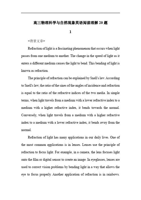
高三物理科学与自然现象英语阅读理解20题1<背景文章>Refraction of light is a fascinating phenomenon that occurs when light passes from one medium to another. The change in the speed of light as it enters a different medium causes the light to bend. This bending of light is known as refraction.The principle of refraction can be explained by Snell's law. According to Snell's law, the ratio of the sines of the angles of incidence and refraction is equal to the ratio of the refractive indices of the two media. In simple terms, when light travels from a medium with a lower refractive index to a medium with a higher refractive index, it bends towards the normal. Conversely, when light travels from a medium with a higher refractive index to a medium with a lower refractive index, it bends away from the normal.Refraction of light has many applications in our daily lives. One of the most common applications is in lenses. Lenses use the principle of refraction to focus light. For example, in a camera, the lens focuses light onto the film or digital sensor to create an image. In eyeglasses, lenses are used to correct vision problems by bending light in a way that allows the eye to focus properly. Another application of refraction is in rainbows.Rainbows are formed when sunlight is refracted and reflected by raindrops. The different colors of the rainbow are due to the different wavelengths of light being refracted at different angles.1. What causes light to bend when it passes from one medium to another?A. The change in the color of light.B. The change in the intensity of light.C. The change in the speed of light.D. The change in the direction of light.答案:C。
Properties of ferroelectricferromagnetic thin film heterostructures
Properties of ferroelectric/ferromagnetic thin film heterostructuresDaming Chen, Ian Harward, Katie Linderman, Evangelos Economou, Yan Nie, and Zbigniew CelinskiCitation: Journal of Applied Physics 115, 17D713 (2014); doi: 10.1063/1.4865316View online: /10.1063/1.4865316View Table of Contents: /content/aip/journal/jap/115/17?ver=pdfcovPublished by the AIP PublishingArticles you may be interested inFerroelectric and ferromagnetic properties in BaTiO3 thin films on Si (100)J. Appl. Phys. 116, 094103 (2014); 10.1063/1.4894508Simultaneous imaging of the ferromagnetic and ferroelectric structure in multiferroic heterostructures APL Mat. 2, 076109 (2014); 10.1063/1.4890055Multiferroic properties of CoFe2O4/Bi3.4La0.6Ti3O12 bilayer structure at room temperatureJ. Appl. Phys. 114, 034108 (2013); 10.1063/1.4815966Ba and Ti co-doped BiFeO3 thin films via a modified chemical route with synchronous improvement in ferroelectric and magnetic behaviorsJ. Appl. Phys. 113, 103904 (2013); 10.1063/1.4794814Magnetoelectric CoFe 2 O 4 – Pb ( Zr , Ti ) O 3 composite thin films derived by a sol-gel process Appl. Phys. Lett. 86, 122501 (2005); 10.1063/1.1889237Properties of ferroelectric/ferromagnetic thin film heterostructuresDaming Chen,1,2,a)Ian Harward,1Katie Linderman,1Evangelos Economou,1Y an Nie,1,3and Zbigniew Celinski 11Center for Magnetism and Magnetic Nanostructures,University of Colorado Colorado Springs,1420Austin Bluffs Pkwy,Colorado Springs,Colorado 80918,USA 2State Key Laboratory of Electronic Thin Films and Integrated Devices,University of Electronic Science and Technology of China,Chengdu,610054Sichuan,China 3School of Optical and Electronic Information,Huazhong University of Science and Technology,1037Luoyu Road,Wuhan,Hubei 430074,China(Presented 7November 2013;received 23September 2013;accepted 7November 2013;published online 11February 2014)Ferroelectric/ferromagnetic thin film heterostructures,SrBi 2Ta 2O 9/BaFe 12O 19(SBT/BaM),were grown on platinum-coated Si substrates using metal-organic decomposition.X-ray diffraction patterns confirmed that the heterostructures contain only SBT and BaM phases.The microwave properties of these heterostructures were studied using a broadband ferromagnetic resonance (FMR)spectrometer from 35to 60GHz,which allowed us to determine gyromagnetic ratio and effective anisotropy field.The FMR linewidth is as low as140Oe at 58GHz.In addition,measurements of the effective permittivity of the heterostructures were carried out as a function of bias electric field.All heterostructures exhibit hysteretic behavior of the effective permittivity.These properties indicate that such heterostructures have potential for application in dual electricand magnetic field tunable resonators,filters,and phase shifters.VC 2014AIP Publishing LLC .[/10.1063/1.4865316]I.INTRODUCTIONMagneto-electric (ME)materials,consisting of ferro-magnetic and piezoelectric (or ferroelectric)phases,etc.,in one material,are of interest for various applications such as filters,phase shifters,inductors,delay lines,resonators,and attenuators.1ME materials can be categorized into single phase materials such as Cr 2O 3,2and two or more phase het-erostructures such as ferromagnetic/ferroelectric (piezoelec-tric),3,4etc.Due to their strong ME coupling,two phase heterostructures have drawn wide attention.The distinguish-ing features of these heterostructures are that they can exhibit not only excellent ferroelectric and magnetic properties simultaneously but also exhibit an ME coupling effect.The ME coupling effect is frequently realized by magnetic field control of electric polarization,or electric field manipulation of the magnetization.Until now,many studies were carried out to investigate the structure,electromagnetic properties,and ME coupling effects in bulk forms or in thin film heterostructures,espe-cially spinel or garnet-based heterostructures.For example,CoFe 2O 4/lead magnesium niobate–lead titanate ((PMN)-PT)bulk composites,5NiFe 2O 4/PMN-PT multiferroic thin film composites,6Li 0.5Àx/2Zn x Fe 2.5Àx/2O 4/niobate–lead titanate (PZT)bilayers,7Ba 0.5Sr 0.5TiO 3/Y 3Fe 5O 12(YIG)bilayers,8and PZT/YIG layered structures 9were investigated,among others.In all these previous works,garnet or spinel ferrites were usually used as the ferromagnetic phase,and they repre-sent the potential for making multiferroic heterostructures-based tunable microwave devices.To use them in millimeterwave devices,however,would require a very high DC bias magnetic field,on the order of 1T or higher.As a result,these structures provide little advantage in terms of achieving mini-aturized millimeter wave devices.Hexagonal ferrite (BaFe 12O 19,BaM)thin films,how-ever,exhibit a large magnetocrystalline anisotropy field and have relatively low microwave losses,making them a very suitable candidate for use in millimeter wave devices,espe-cially when compared to garnets or spinel ferrites.Moreover,BaM thin films with high remanence values could allow one to bias a device with zero or reasonably low dc magnetic fields (self-biased devices).Recently,Ustinov et al.10reported electric tuning of the ferromagnetic reso-nance (FMR)frequency near 100GHz in a BaM/PZT bilayer,and found a magneto-electric coefficient of 0.37Oe cm/kV.Das et al.3also demonstrated electric tuning of the FMR frequency near 60GHz in BaM/BST heterostructures.These experiments clearly indicate that it is possible to pre-pare BaM-based heterostructures that exhibit ferroelectric and ferromagnetic properties simultaneously,and at the same time exhibit reasonable ME coupling.The choice of the ferroelectric (or piezoelectric)material is,however,of paramount importance since it determines the overall per-formance of the structure.In this work,our choice of the ferroelectric material was strontium bismuth tantalate (SrBi 2Ta 2O 9,SBT),which has good endurance,low switching voltage,and low leakage cur-rent as compared to PZT.SBT has been used in ferroelectric memories with very good endurance exceeding 109writ-e/read operations.The goal of the work was to fabricate and determine the structural,magnetic,and electric properties of SrBi 2Ta 2O 9/BaFe 12O 19(SBT/BaM)thin film heterostructures for possiblea)Author to whom correspondence should be addressed.Electronic mail:chendaming1986@.0021-8979/2014/115(17)/17D713/3/$30.00VC 2014AIP Publishing LLC 115,17D713-1JOURNAL OF APPLIED PHYSICS 115,17D713(2014)use at millimeter wave devices.In addition,we aim to develop these structures on a Si substrate.II.EXPERIMENTAL DETAILSSBT/BaM thin film heterostructures were grown by metal-organic decomposition.First,we grew BaM on a Pt-coated Si wafer,the detailed procedure for which can be found elsewhere.11Next,SrBi 2Ta 2O 9precursors were spin-coated on top of the BaM thin film at 3000rpm for 30s,creating a uniform wet film.The film was annealed immedi-ately on hot plates in air at 165,250,and 390 C for 1,4,and 4min,respectively.Then,the samples were annealed in O 2at 700 C for 60s in a rapid thermal annealing (RTA)unit with a ramping rate of 5 C/min.This procedure was carried out twice to build up an SBT film with the desired thickness.The total thickness of the BaM layer was 115nm,while the thickness of the SBT was 220nm.The crystallographic structure and the surface morphol-ogy were investigated by X-ray diffraction (XRD)and atomic force microscopy (AFM),respectively.The capaci-tance and C-V characteristic curves were measured usingHP4192A LF Impedance Analyzer.The dynamic mag-netic response was measured on a vector network analyzer-based broadband FMR system from 35GHz to 60GHz.12The static magnetic properties of the samples were studied by a superconducting quantum interference device (SQUID)magnetometer.To determine the effective permittivity and leakage cur-rent,we coated the heterostructure with Cu as a top electrode,and patterned arrays of cylinders (7-80l m diameters),effec-tively producing capacitor arrays for measurement.The top Cu electrode was deposited using magnetron sputtering,and photolithography and wet etching was used for patterning.III.RESULTS AND DISCUSSIONX-ray diffraction patterns of a BaM thin film on Pt and an SBT/BaM thin film heterostructure on Pt are shown in Figure 1.The heterostructure contains only SBT and BaM phases,no other phase can be detected.This indicates that our growth procedure produces heterostructures in which these two phases can coexist without any intermixing.An example of the heterostructure magnetic hysteresis loop measurements is shown in Figure 2.These measure-ments clearly indicate that the magnetic properties of the BaM layer are not affected by the presence of the SBT layer.The BaM layer exhibits strong out of plane anisotropy and large remanence,as expected for a single BaM film grown on a Pt template by MOD.This conclusion is further sup-ported by the FMR measurements.Figure 3shows the FMR results of a BaM layer before and after deposition of the SBT layer.The FMR frequency is a linear function of the applied field.This allowed us to determine the values of the uniaxial anisotropy field (16.9and 16.7for BaM and BaM/SBT structure,respectively)and thegyromagneticFIG.1.XRD patterns of BaM and SBT/BaMstructures.FIG. 2.Magnetization as a function of the applied field SBT/BaMheterostructure.FIG. 3.FMR frequency as a function of applied field for BaM and SBT/BaMstructures.FIG. 4.Linewidth as a function of the FMR frequency for BaM and SBT/BaM structures.ratio,c ¼2.75GHz/kOe.These values are basically unchanged when the properties of BaM and SBT/BaM struc-tures are compared.Moreover,not only did we not observed any changes in the measured value of FMR linewidth to within experimental error but also the measured values are relatively low (see Figure 4).This is an important result which clearly indicates the relatively high quality of our structures,because the linewidth is extremely sensitive to any changes of magnetic properties.Any intermixing would result in FMR line broadening,which was not observed.The dielectric characterization of the SBT/BaM struc-ture is based on C-V measurements,the results of which are depicted in Fig.5.The effective relative permittivity of thestructure changes with an applied voltage (electric field)and exhibits typical ferroelectric material hysteretic behavior.This indicates good ferroelectric properties of the SBT layer.Furthermore,we measured the leakage current in our struc-tures and found that it is very low (see Fig.6),with values on the level of 1mA/cm 2.Since these measurements were carried out on relatively large structures (electrode size of 80l m in diameter),the small leakage current indicates good structural integrity of our structures.IV.CONCLUSIONWe have prepared a series of SBT/BaM heterostructures with good dielectric and magnetic properties.The magnet-ization in these structures is out of plane and the structures exhibit good high frequency properties,with high uniaxial magnetic anisotropy and low FMR linewidth.The effective permittivity of the entire structure can be adjusted with an applied voltage,meaning these heterostructures have prom-ise for high frequency voltage tuned millimeter wave signal processing devices.ACKNOWLEDGMENTSThis work was supported by the ARO Grant No.W911NF-10-1-0225.One of us (Daming Chen)would like to thank China Scholarship Council for the support.1N.X.Sun and G.Srinivasan,Spin 2(3),1240004(2012).wes and G.Srinivasan,J.Phys.D:Appl.Phys.44,243001(2011).3J.Das,Y.Y.Song,and M.Wu,J.Appl.Phys.108,043911(2010).4A.S.Tatarenko,A.tinov,G.Srinivasan,V.M.Petrov,and M.I.Bichurin,Appl.Phys.108,063923(2010).5A.D.Sheikh and V.L.Mathe,J.Phys.Chem.Solids 72,1423(2011).6N.Li,M.Liu,Z.Zhou,N.X.Sun et al .,Appl.Phys.Lett.99,192502(2011).7tinov,V.S.Tiberkevich,G.Srinivasan,and A.N.Slavin,J.Appl.Phys.100,093905(2006).8tinov,B.A.Kalinikos,V.S.Tiberkevich,A.N.Slavin,and G.Srinivasan,J.Appl.Phys.103,063908(2008).9A.S.Tatarenko,G.Srinivasan,and M.I.Bichurin,Appl.Phys.Lett.88,183507(2006).10tinov and G.Srinivasan,Appl.Phys.Lett.93,142503(2008).11I.Harward,Y.Nie,D.Chen et al .,J.Appl.Phys.113,043903(2013).12I.Harward,T.O.Keevan,A.Hutchison,V.Zagorodnii,and Z.Celinski,Rev.Sci.Instrum.82,095115(2011).FIG.6.Leakage current as a function of applied voltage in SBT/BaMheterostructures.FIG.5.Relative permittivity of the SBT/BaM heterostructure as a function of applied voltage.。
Hidden magnetic transitions in thermoelectric layered cobaltite, [Ca$_2$CoO$_3$]$_{0.62}$[C
a r X i v :c o n d -m a t /0308066v 1 [c o n d -m a t .s t r -e l ] 5 A u g 2003APS/PRBHidden magnetic transitions in thermoelectric layered cobaltite,[Ca 2CoO 3]0.62[CoO 2]J.Sugiyama 1,∗J.H.Brewer 2,E.J.Ansaldo 3,H.Itahara 1,K.Dohmae 1,Y.Seno 1,C.Xia 1,and T.Tani 11Toyota Central Research and Development Labs.Inc.,Nagakute,Aichi 480-1192,Japan2TRIUMF,CIAR and Department of Physics and Astronomy,University of British Columbia,Vancouver,BC,V6T 1Z1Canada and3Department of Physics,University of Saskatchewan,Saskatoon,SK,S7N 5A5Canada(Dated:February 6,2008)A positive muon spin rotation and relaxation (µ+SR)experiment on [Ca 2CoO 3]0.62[CoO 2],(i.e.,Ca 3Co 4O 9,a layered thermoelectric cobaltite)indicates the existence of two magnetic transitions at ∼100K and 400-600K;the former is a transition from a paramagnetic state to an incommensurate (IC )spin density wave (SDW )state.The anisotropic behavior of zero-field µ+SR spectra at 5K suggests that the IC-SDW propagates in the a -b plane,with oscillating moments directed along the c -axis;also the IC-SDW is found to exist not in the [Ca 2CoO 3]subsystem but in the [CoO 2]subsystem.In addition,it is found that the long-range IC-SDW order completes below ∼30K,whereas the short-range order appears below 100K.The latter transition is interpreted as a gradual change in the spin state of Co ions above 400K.These two magnetic transitions detected by µ+SR are found to correlate closely with the transport properties of [Ca 2CoO 3]0.62[CoO 2].PACS numbers:76.75.+i,75.30.Fv,75.50.Gg,72.15.JfKeywords:thermoelectric layered cobaltites,magnetism,muon spin rotation,incommensurate spin density waves,spin state transitionI.INTRODUCTIONA strong correlation between 3d electrons induces im-portant physical properties in 3d metal oxides;e .g .high temperature superconductivity in cuprates,colos-sal magnetoresistance in manganites and probably ’good’thermoelectric properties in layered cobaltites.Four cobaltites,[Ca 2CoO 3]0.62[CoO 2],[1,2,3]Na x CoO 2with x ∼0.6,[4,5,6][Sr 2Bi 2−y Pb y O 4]x [CoO 2],[7,8,9]and [Ca 2Co 4/3Cu 2/3O 4]0.62[CoO 2],[10]are known to be good thermoelectrics because of their metallic conductiv-ities and high thermoelectric powers,for reasons which are currently not fully understood.In order to find ex-cellent thermoelectrics suitable for thermoelectric power generation for protecting the environment by saving en-ergy resources and reducing the release of CO 2into the atmosphere,it is crucial to understand the mechanism of the ’good’thermoelectric properties in these layered cobaltites.The layered cobaltites share a common structural com-ponent:the CoO 2planes,in which a two-dimensional-triangular lattice of Co ions is formed by a network of edge-sharing CoO 6octahedra.Charge carrier transport in these materials is thought to be restricted mainly to these CoO 2planes,as in the case of the CuO 2planes for the high-T c cuprates.Since specific heat measure-ments on Na x CoO 2indicate a large thermal effective mass of carriers [11],all these cobaltites are believed to be strongly correlated electron systems.2µ+SR time spectra in[Ca2CoO3]0.62[CoO2]at tempera-tures below700K.The former method is sensitive to lo-cal magnetic order via the shift of theµ+spin precessionfrequency and the enhancedµ+spin relaxation,whileZF-µ+SR is sensitive to weak local magnetic[dis]order insamples exhibiting quasi-static paramagnetic moments.II.EXPERIMENTA randomly oriented polycrystalline disk(∼20mm diameter and∼2mm thick)of[Ca2CoO3]0.62[CoO2] was synthesizedby a conventional solid state reac-tion technique[13].C-axis aligned polycrystalline [Ca2CoO3]0.62[CoO2]and[Ca1.8M0.2CoO3]0.62[CoO2] (M=Sr,Y,Bi)plates(∼20×20×2mm3)were syn-thesized by a reactive templated grain growth technique [15].Single-crystal platelets of[Ca2CoO3]0.62[CoO2](∼5×5×0.1mm3)were prepared by a SrCl2flux method [16].Then,all the samples were annealed in an O2flow at 450o C for12hours.The preparation and characteriza-tion of these samples were described in detail elsewhere [17,18].TheµSR experiments were performed on the M20and M15surface muon beam line at TRIUMF. The experimental setup is described elsewhere[19].III.RESULTSA.IC-SDW transitionIn all the[Ca2CoO3]0.62[CoO2]samples,the wTF-µ+SR spectra in a magneticfield of H∼100Oe exhibit a clear reduction of theµ+precession amplitude below 100K.The data were obtained byfitting the wTF-µ+SR spectrum in the time domain with a combination of a slowly relaxing precessing signal and two non-oscillatory signals,one fast and the other slow relaxing:A0P(t)=A PARA exp(−λPARA t)cos(ωµt+φ)+A fast exp(−λfast t)+A slow exp(−λslow t),(1) where A0is the initial asymmetry,P(t)is the muon spin polarization function,ωµis the muon Larmor frequency,φis the initial phase of the precession and A n andλn(n =PARA,fast and slow)are the asymmetries and expo-nential relaxation rates of the three signals.The latter two signals(n=fast and slow)havefinite amplitudes below T on SDW≈100K and probably suggest the existence of multiple muon sites in[Ca2CoO3]0.62[CoO2]. Figures1(a)and1(b)show the temperature depen-dences of the paramagnetic asymmetry A PARA(which is proportional to the volume fraction of a paramagnetic phase in the sample)and the corresponding relaxationλPARA(16s-1)TEMPERATURE (K)APARAFIG.1:(a)Paramagneticµ+spin precession asymmetry A PARA and(b)muon spin relaxation rateλPARA as a function of temperature for the three[Ca2CoO3]0.62[CoO2]samples:a randomly oriented polycrystalline disk(solid circles)[13],a c-axis aligned polycrystalline plate(squares)and single crys-tal(sc)platelets(open circles).For the sc platelets,both the value of A PARA above100K and the change in A PARA below 100K are smaller than those in the polycrystalline samples. This is because the muon momentum was decreased from28 to25MeV/c for the sc measurements to stop muons in the thin platelets(∼100µm thickness),causing a small back-ground signal from muons stopping elsewhere.rateλPARA in three[Ca2CoO3]0.62[CoO2]samples:a ran-domly oriented polycrystalline sample[13],a c-aligned polycrystalline sample,and single crystal platelets.The large decrease in A PARA below100K(and the accompa-nying increase inλPARA)indicate the existence of a mag-netic transition with an onset temperature T on c≈100K and a transition width∆T≈70K.The single crystal data suggest that the large∆T is not caused by inhomo-geneity of the sample but is an intrinsic property of this compound.Figure2shows ZF-µ+SR time spectra at4.8K in the c-aligned sample;the top spectrum was obtained with the initialµ+spin direction Sµ(0)perpendicular to the c-axis and the bottom one with Sµ(0) ˆc.A clear oscillation due to quasi-static internalfields is observed only when Sµ(0)⊥ˆc.The time interval from t=0to thefirst zero crossing of that oscillation is roughly the same(1: 1.2954)as the interval between thefirst and second zero crossings;this is a characteristic of a zeroth-order Bessel3c-aligned[Ca 2CoO 3]0.62[CoO 2]ZF-µ+SR at 4.8 KS µ(0)c//S µ(0)c0.050.100.100.10.2TIME (µs)A S Y M M E T R Y ~~~~FIG.2:ZF-µ+SR time spectra of the c -aligned [Ca 2CoO 3]0.62[CoO 2]plate at 4.8K.The configurations ofthe sample and the initial muon spin direction Sµ(0)are (top) Sµ(0)⊥ˆc and (bottom) S µ(0) ˆc .function of the first kind J 0(ωµt )that describes the muon polarization evolution in anincommensurate spin density wave IC-SDW field distribution [19,20,21].Actually,the top oscillating spectrum was fitted using a combination of three signals:A 0P (t )=A SDW J 0(ωµt )exp(−λSDW t )+A KT G KT zz (t,∆)+A tail exp(−λtail t ),(2)ωµ≡2πνµ=γµH int ,(3)G KT zz (t,∆)=131−∆2t 2 exp(−∆2t 2/2),(4)where A 0is the empirical maximum muon decay asym-metry,A SDW ,A KT and A tail are the asymmetries as-sociated with the three signals,G KT zz (t,∆)is the static Gaussian Kubo-Toyabe function,∆is the static width of the distribution of local frequencies at the disordered sites and λtail is the slow relaxation rate of the ’tail’(not shown in this Figure),and the fit using an exponential re-laxed cosine oscillation,exp(−λt )cos(ωµt +φ),provides a phase angle φ∼90o ,which is physically meaningless.[22]We therefore conclude that [Ca 2CoO 3]0.62[CoO 2]un-dergoes a magnetic transition from a paramagnetic stateto an IC-SDW state (i.e.T on c =T onSDW ).The absence ofλS D W(106 s -1)TEMPERATURE (K)νµ(M H z )AFIG.3:Temperature dependences of (a)A SDW and A PARA (estimated by the wTF-µ+SR experiment),(b)νµand (c)λSDW fot the c -aligned [Ca 2CoO 3]RS 0.62[CoO 2].The solid line in Fig.3(b)represents the temperature dependence of the BCS gap energy.The deviation of the experimental data from the theory around 20K is probably due to the effect of the ferrimagnetic transition at 19K.a clear oscillation in the bottom spectrum of Fig.2in-dicates that the internal magnetic field Hint is roughly parallel to the c -axis,since the muon spins do not pre-cess in a parallel magnetic field.The IC-SDW is un-likely to propagate along the c -axis due both to the two-dimensionality and to the misfit between the two subsys-tems.The IC-SDW is therefore considered to propagate in the a -b plane,with oscillating moments directed along the c -axis.This suggests that the ferrimagnetic interac-tion is also parallel to the c -axis,and is consistent with the results of our χmeasurement on single crystals.[23]4Figures 3(a)-3(c)show the temperature dependences of A SDW ,A KT and A PARA (same in Fig.1),νµand λSDW and ∆for the c -aligned [Ca 2CoO 3]RS 0.62[CoO 2].A SDW increases with decreasing T below 30K,although A PARA obtained by the wTF-µ+SR measurement exhibits a rapid decrease below 100K and levels offto almost 0below 30K (see Fig.3(a)).According to the recent χmeasurements us-ing single crystal platelets,[23]a small shoulder in the χ(T )curve was observed at 27K only for H ⊥ab .This temperature (27K)corresponds to the highest temper-ature that a clear µ+SR signal due to the IC-SDW was observed.Thus,it is considered that a short-range or-der IC-SDW state appears below 100K =T onSDW ,while the long-range order is completed below 27K;i.e.,T SDW=T end SDW .Since both ρ(T )and S (T )are metallic above 80K and semiconducting below 80K,[2,3]charge car-rier transport is strongly affected by a formation of the short-range IC-SDW order.Although the νµ(T )curve is well explained by the BCS weak coupling theory as expected for the IC-SDW state,[24]there is a deviation from the theory around 20K (see Fig.3(b)).This deviation (and the accompa-nying increase in A SDW )is probably due to the effect of the ferrimagnetic transition at 19K (=T FR ).Here,the ferrimagnetism is considered to be caused by an interlayer coupling between Co spins in the [Ca 2CoO 3]and [CoO 2]subsystems,[23]while the IC-SDW order completes below 27K.This means that the IC-SDW is affected by the fer-rimagnetic coupling via.the Co spins in the [Ca 2CoO 3]subsystem.Therefore,the enhancement of the internal magnetic field at T FR is likely to be caused by a criti-cal phenomenon around the ferrimagnetic transition.In addition,the magnitude of λSDW decreases rapidly with decreasing T and levels offto a constant value below 20K.This suggests that the broadening of the IC-SDW field distribution at the µ+sites mainly occurs in the temperature range between T SDW and T FR .In order to determine the subsystem in which the IC-SDW exists,ZF-µ+SR spectra were mea-sured in doped samples:c -aligned polycrystalline [Ca 1.8M 0.2CoO 3]0.62[CoO 2](M =Sr,Y and Bi).A clear precession was observed in the ZF-µ+SR spectrum with Sµ(0)⊥ˆc in every sample,although T SDW depended on dopant.Figure 4shows the temperature dependences of νµfor the c -aligned pure and doped [Ca 2CoO 3]RS 0.62[CoO 2]samples.Doping with Y and Bi increase T SDW by ∼40K and Sr-doping by ∼20K,although Sr-doping did not af-fect T onSDWby the previous wTF-µ+SR experiment.[13]It should be noted that all the samples show approx-imately the same precession frequency (∼60MHz)atzero temperature.This suggests that the local magnetic field H int (0K)is independent of dopant.Since H int in the doped [Ca 2CoO 3]subsystem should be strongly affected by the dopant,it is concluded that the IC-SDW exists not in the [Ca 2CoO 3]subsystem but in the [CoO 2]subsystem.Also,the latest µ+SR experiment onνµ(M H z )TEMPERATURE (K)FIG.4:Temperature dependences of νµfor the c -aligned pure and doped [Ca 2CoO 3]RS 0.62[CoO 2].The dotted lines represent the temperature dependence of the BCS gap energy.[Ca 2Co 4/3Cu 2/3O 4]0.62[CoO 2],[25]which consists of the quadruple rocksalt-type subsystem and the single [CoO 2]subsystem,also indicates the existence of an IC-SDW state below ∼200K.The precession frequency due to an internal IC-SDW field is estimated as ∼60MHz at zero temperature.This strongly suggests that the IC-SDW exists in the [CoO 2]subsystem,because one third of the Co ions in the rocksalt-type subsystem are replaced by Cu ions.Therefore,the IC-SDW is found to be caused by the spin-order of the conduction electrons in the [CoO 2]subsystem.B.Spin State TransitionThe high-temperature wTF-µ+SR spectra were mea-sured in an air flow to avoid the formation of oxy-gen deficiency in the sample,whereas the previous experiment in vacuum.[14]The spectra in the c -aligned [Ca 2CoO 3]0.62[CoO 2]sample were well fit-ted using an exponential relaxed cosine oscillation,A PARA exp(−λPARA t )cos(ωµt +φ).Figures 5(a)-5(d)show the temperature dependences of A PARA ,λPARA ,the shift of ωµ(∆ωµ)and the inverse susceptibility χ−1in the c -aligned polycrystalline [Ca 2CoO 3]0.62[CoO 2]sample and a polycrystalline [Ca 1.8Y 0.2CoO 3]0.62[CoO 2]sample.Here,∆ωµis defined as (ωµ(T )-ωµ(300K))/ωµ(300K);since the oscillation of a reference was not measured,∆ωµis inequivalent to the muonic Knight shift.A broad shoulder is clearly seen in the λPARA (T )curve of the pure sample at 400-600K,although such a5∆ωµ (%)A P A R AλP A R A(106 s -1)χ-1 (103 g /e m u )TEMPERATURE (K)FIG.5:Temperature dependences of (a)the asymme-try A PARA (b)the muon spin relaxation rate λPARA (c)the shift of the muon precession frequency ∆ωµand (d)the inverse susceptibility χ−1in a c -aligned polycrystalline [Ca 2CoO 3]0.62[CoO 2]sample (circles)and a polycrystalline [Ca 1.8Y 0.2CoO 3]0.62[CoO 2]sample (diamonds);A PARA and λPARA was obtained by fitting the wTF-µ+SR spectrum in the time domain using a simple exponential relaxation function,A PARA exp(−λPARA t )cos(ωµt +φ).shoulder seems to be ambiguous in the Y-doped sam-ple [Fig.5(b)].Moreover,as T increases,the ∆ωµ(T )curve exhibits a sudden decrease at ∼400K,while the ∆ωµ(T )curve in the Y-doped sample is roughly indepen-dent of T .It should be noted that,as seen in Figs.1(a)and 5(a),above 150K A PARA levels offto its maximumvalue (∼0.26)—i.e.the sample volume is almost 100%paramagnetic.In addition,there is no thermal hysteresis in the data for the c -aligned [Ca 2CoO 3]0.62[CoO 2]sample obtained on heating and on cooling.This suggests that the changes in the λPARA and the ∆ωµare not caused by the formation of oxygen deficiency but by a magnetic transition,as discussed later.These behaviors are in good agreement with the results of χ(T )measurements.That is,the χ−1(T )curve of the pure sample exhibits an obvious change in slope at T χSS =380K,while that of the Y-doped sample does not [Fig.5(d)].The change in the χ−1(T )curve is considered to be attributed to the spin state transition of the Co 3+and Co 4+ions from the low temperature LS or LS +IS to the high-temperature LS +IS ,IS ,IS +HS or HS ,[2,23]as in the case of LaCoO 3.[26,27]Here LS ,IS and HSare the low-spin (t 62g ;S =0and t 52g ;S =1/2),intermediate-spin (t 52g e 1g ;S =1and t 42g e 1g ;S =3/2)and high-spin (t 42g e 2g ;S =2and t 32g e 2g ;S =5/2)states,respectively.At these temperatures muons are diffusing rapidly,so that the relaxation rate usually decreases monotonically with increasing temperature.Hence we can conclude that both the shoulder in the λPARA (T )curve and the sudden decrease in the ∆ωµ(T )curve are induced by the spin state transition,because there is no indications for the appearance of a magnetically ordered state (see Fig.5(a)).Therefore,the spin state transition from the low-temperature LS to the high-temperature IS +HS or HS is most reasonable to explain the change in H int (sug-gested by the changes in λPARA (T )and ∆ωµ(T ))without the magnetic order,i.e.,the temperature independent A PARA (T ).On the other hand,both the rapid muon dif-fusion and the fast exchange rate of electrons between Co 3+and Co 4+ions decrease λPARA with increasing T .The competition between these three factors is likely re-sponsible for the broad shoulder in λPARA (T )around 400-600K.In order to know the contribution from the latter two factors,Fig.6shows the relationship between λPARA and T −1of the pure and Y-doped samples,because the latter two factors are expected to depend on exp(T −1).Never-theless,the linear relationship is not observed even in the Y-doped sample;thus,it is difficult to separate the con-tribution from each factor at present,although the dif-ference between both samples are clearly seen in Fig.6.Indeed,the λPARA (T )curves of the pure and Y-doped samples seem to level offto a constant value (∼0.01×10⁶sec −1)above 650K due to a rapid muon diffusion,as in the case of YBa 2Cu 3O 6±δ.[28,29]Therefore,wecan not determine the onset temperature (T onSS )of the broad shoulder in the λPARA (T )curve ,based only onthe present µ+SR result,although T onSS ≥600K.The broad shoulder also suggests the possibility that the spin state changes gradually above 400K.In other words,T on SS ≥600K and the endpoint T endSS =T χSS =380K.Andat temperatures between T on SS and T endSS ,the populations6λP A R A(106 s -1)1000/T (K -1)FIG.6:Muon spin relaxation rate λPARA as a function of T −1in a c -aligned polycrystalline [Ca 2CoO 3]0.62[CoO 2]sam-ple (circles)and a polycrystalline [Ca 1.8Y 0.2CoO 3]0.62[CoO 2]sample (diamonds).A discontinuous in data at 300K was caused by the change in the experimental setup from a cryo-stat to an oven.of the IS and HS states are likely to vary as a func-tion of temperature,as in the case of LaCoO 3.[26,27]The relationship between the spin state transition and the transport properties is discussed later.IV.DISCUSSIONA.The nature of IC-SDWThere are two Co sites in the [Ca 2CoO 3]RS 0.62[CoO 2]lattice;thus,it is difficult to determine the Co valence in the [CoO 2]plane by a χmeasurement or a chemi-cal titration technique,although both Co 3+and Co 4+ions are mainly in the LS state below T endSS ,according to the photo-emission and x-ray absorption studies on the related cobaltiets,[Sr 2Bi 2−y Pb y O 4]x [CoO 2][30]and χmeasurements on several cobaltites.[2,3,7,13,31]If we assume that only Co 3+and Co 4+ions exist in [Ca 2CoO 3]RS 0.62[CoO 2]the average valence of the Co ions in the [CoO 2]plane is calculated as +3.38.This value is similar to the nominal valence of Co ions in Na 0.6CoO 2.Hence,the Co spins with S =1/2are considered to oc-cupy 40%corners in the two dimensional triangular lat-tice to minimize an electric repulsion and a geometrical frustration in the IC-SDW state.It is worth noting that the µ+sites are bound to the O ions in the [CoO 2]plane.This means that the µ+mainly feel the magnetic field in the [CoO 2]plane.Thus,the IC-SDW is most unlikely to be caused by the misfit between the two subsystems,but to be an intrinsic be-havior of the [CoO 2]plane.Nevertheless,the structure of the IC-SDW order is still unknown at present,because the current µ+SR experiments provide no information on the incommensurate wave vector.In order to obtain such information,it is necessary to carry out both 59Co-NMR and neutron scattering experiments on these cobaltites.B.Calculation and other experiments on IC-SDWThe IC-SDW order in [Ca 2CoO 3]RS 0.62[CoO 2]is assigned to be a spin (S =1/2)order on the two-dimensional tri-angular lattice at non-half filling.Such a problem was investigated by several workers using the Hubbard model within a mean field approximation;[32,33,34,35]H =−t<ij>σc †iσc jσ+U in i ↑n i ↓,(5)where c †iσ(c jσ)creates (destroys)an electron with spin σon site i ,n iσ=c †iσc iσis the number operator,t is the nearest-neighbor hopping amplitude and U is the Hub-bard on-site repulsion.The electron filling n is definedas n =(1/2N ) Ni n i ,where N is the total number of sites.At T =0and n =0.5(i.e.,the average valence of the Co ions in the [CoO 2]plane is +4),as U increased from 0,the system is paramagnetic metal up to U/t ∼3.97,and changes into a metal with a spiral IC-SDW ,and then at U/t ∼5.27,a first-order metal-insulator transition occurs.[32]On the other hand,at n =0.81(i.e.,the aver-age valence of the Co ions in the [CoO 2]plane is +3.38),a spiral SDW state is stable below U/t ∼3.[33]These calculations suggest that the IC-SDW state is stable for a weak-to-moderate coupling (U/t ≤5).Also,the IC-SDW phase boundary was reported to depend on n ;that is,in the n range between 0.75and 1,the largest U/t for the IC-SDW phase increased monotonically with increasing n .[33]Since larger U/t stabilize the energy gap at higher temperature,[35]the calculations are consistent with the present µ+SR results,i.e.,the large increase in T SDW due to the Y-or Bi-doping into [Ca 2CoO 3]RS 0.62[CoO 2].On the other hand,our preliminary heat capacity measurements using single crystal and c -aligned poly-crystal [Ca 2CoO 3]RS 0.62[CoO 2]samples indicate that the electronic specific heat parameter γranges from 60to 90mJK −2per mol [CoO 2],if we ignore the magnetic con-tribution.This value is higher than that for Na x CoO 2with x ∼0.5(γ∼24mJK −2per mol Co).[11]Thus,[Ca 2CoO 3]RS 0.62[CoO 2]seems to be a strongly correlated electron system,as well as Na x CoO 2.As a result,it is expected that U ≫t ,although the above calculations suggest U/t ≤5.In order to solve this puzzle,it is nec-essary to determine the IC-SDW structure at first.According to the recent photoelectron spectroscopic study on [Ca 2CoO 3]RS 0.62[CoO 2]below ambient tempera-ture,the density of states DOS at the Fermi level E F de-7λp a r a(106 s -1)TEMPERATURE (K)λp a r a(106 s -1)FIG.7:Temperature dependences of the muon spin relax-ation rate λPARA for the [Ca 2CoO 3]0.62[CoO 2]sample mea-sured (a)in vacuum[14]and (b)in an air flow.creased with decreasing T and disappeared at 10K.[36]Thus,the energy gap was clearly observed at 10K.This also supports our conclusion;that is,both the broad min-imum at ∼80K in the ρ(T )curve and the rapid increase in ρbelow 80K with decreasing T are caused by the IC-SDW order between the spins of the conduction electrons and not by a magnetic scattering,such as,the Kondo ef-fect.C.Effect of Oxygen Deficiency on Spin StateTransitionIn order to know the effect of atmosphere during the measurement,Fig.7shows the comparison of the previous[14]and the present λPARA (T )curve;the former was measured in vacuum and the latter in an air flow.There is a clear thermal hysteresis in the λPARA (T )curve obtained in vacuum.In addition,the broad maximum between 400and 600K looks very ambiguous in the data obtained in vacuum compared with that in an air flow.Recently,it was reported that oxygens are removed from [Ca 2CoO 3]0.62[CoO 2]above 723K (=450o C)even in an oxygen flow.[37]Therefore,both the clear thermal hys-teresis and the suppression of the broad maximum in the λPARA (T )curve obtained in vacuum are induced by the formation of oxygen deficiency.As well as the oxy-gen deficiency,the substitution of Ca by Y decreases the average Co valence;[13]as a result,the λPARA (T )curve of the Y-doped sample looks quite similar to that of[Ca 2CoO 3]0.62[CoO 2]obtained in vacuum on cooling (see Fig.5(b)and Fig.7(a)).D.Relationship between Spin State Transition andTransport PropertiesThe broad shoulder in the λPARA (T )curve at 400-600K is in good agreement with the behavior of the ρ(T )curve,because the ρ(T )curve shows a broad maximum between 400and 600K,and above 600K ρdecreases monotonically with increasing T up to 1000K.[2,38]On the other hand,the S (T )curve exhibits a small changein slope around T χSS ;that is,as T increases from 0K,S increases monotonically up to ∼100K and seems to level offa constant value (∼130µVK −1)up to ∼400K,then S again increases linearly (d S /d T ∼80nVK −2)upto 1000K.[2,38]Therefore,above T endSS ,the ρ(T )curve exhibits a semiconducting behavior,whereas the S (T )curve metallic.The two Co sites in the [Ca 2CoO 3]RS 0.62[CoO 2]lattice leads to a question which is responsible for the spin state transition,as in the case of IC-SDW order.Both the change in slope of S (T )at ∼400K and the broad max-imum of ρ(T )at 400-600K suggest that the Co ions in the [CoO 2]plane play a significant role on the spin state transition.Indeed,the related cobaltites,Na 0.9[CoO 2]and Na x Ca y [CoO 2],were reported to exhibit a small magnetic anomaly around 300K,[46,47]probably in-dicating the existence of a spin state transition,although the [CoO 2]plane was considered to be rigid due to a net-work of edge-sharing CoO 6octahedra.Hence,the Co ions in the [CoO 2]planes are most likely to change their spin state at 400-600K.The existence of the spin state transition suggests that the crystal-field splitting between t 2g and e g levels is com-parable to ∼400K.Thus,above T endSS ,charge carrier transport in the [CoO 2]plane is considered to be domi-nated by not only the direct hopping of the t 2g electrons between the Co ions [39]but also the hybridization be-tween Co-e g levels and O-2p levels,as in the case of the perovskite LaCoO 3.[40]Indeed,ρof LaCoO 3decreased with increasing T above 500K,[41]which is the tempera-ture of the apparent spin state transition from LS to IS accompanied with an insulator-to-metal transition.If we employ the modified Heikes formula using the degeneracy of spin and orbital degrees of freedom of Co ions,[42]the value of S T →∞is calculated as 154µVK −1,when the concentration of Co 4+is equivalent to that of Co 3+and both Co 3+and Co 4+are in the LS state.Inorder to explain the observed S (T )curve above T endSS ,itis necessary to assume that Co 3+is in the LS state and Co 4+in the LS +IS state;under this assumption,we obtain S T →∞=293µVK −1,although such inequivalent spin state is unlikely to exist at elevated temperatures.8T (K)19100380600FR PM (LS)PM(IS+HS)?PM (HS)?T FR30T SD WT SDWonT SSendT SSonIC-SDW (SRO)metallic insulating semiconductingIC-SDW (LRO)FIG.8:Successive magnetic transitions in [Ca 2CoO 3]0.62[CoO 2].The bold arrows indicate the transitions found by the present and the previous µ+SR experiments,[13,14]while the narrow arrows show those detected by the previous susceptibility measurements.[2,13]In Fig.8,FR means ferrimagnetic,PM paramagnetic and LS ,IS and HS low-,intermediate-and high-spin state,respectively;and IC-SDW incommensurate spin density wave state,LRO and SRO long-range and short-range order.Thespin states above T endSS ≈380K are not clear at present.Our χmeasurements using single crystal platelets of [Ca 2CoO 3]0.62[CoO 2]showed a clear thermal hysteresis with a width of ∼25K for the spin state transition at T end SS .[23]The thermal hysteresis was also confirmed by a heat capacity measurement.[43]These indicate that the spin state transition accompanies a structural change,as well as the case of LaCoO 3around 100K and 500K detected by neutron diffraction measurements.[44,45]Hence,in order to elucidate the mechanism of the spin state transition,further µ+SR experiments on the related cobaltites,such as Na 0.9[CoO 2]and Na x Ca y [CoO 2],are necessary;in particular,a precise muonic Knight shift measurement would provide a significant information on the change in H int during the spin state transition.In addition,we need an x-ray and/or neutron diffraction analysis for [Ca 2CoO 3]RS 0.62[CoO 2]as a function of tem-perature,to obtain the information on structural change,which would affect the magnitude and distribution ofH int above T endSS.Furthermore,the photo-emission and x-ray absorption studies on [Ca 2CoO 3]0.62[CoO 2]at el-evated temperatures are needed to determine the spin state for understanding the transport properties above T end SS .V.SUMMARYWe investigated the magnetism of the misfit layered cobaltite,[Ca 2CoO 3]0.62[CoO 2],by a positive muon spinrotation and relaxation experiment.It is found that [Ca 2CoO 3]0.62[CoO 2]exhibits the successive magnetic transitions,as summarized in Fig.8.An incommensu-rate (IC )spin density wave (SDW )is observed directly by ZF-µ+SR below about 30K,and evidence for theonset of the IC-SDW state is seen below T onSDW ≈100K,while the muon spin relaxation is characteristic of a para-magnet (PM)above T onSDW .Therefore,we conclude that the long-range IC-SDW order completes below ∼30K,whereas the short-range order appears below 100K.Also the IC-SDW is found to propagate in the [CoO 2]plane,with oscillating moments directed along the c -axis.Be-low T FR ≈19K,the IC-SDW apparently coexists with ferrimagnetism (FR ).At 400-600K,the spin state of Co ions changes;that is,the populations of the low-,intermediate-and high-spin states are most likely to vary gradually with increas-ing temperature above 380K (=T endSS ).Also,this tran-sition is found to be sensitive to the Co valence,which is controlled by doping and/or oxygen deficiency.These two magnetic transitions detected by µ+SR are found to correlate closely with the transport properties of [Ca 2CoO 3]0.62[CoO 2];in particular,both a broad mini-mum at around 80K and a broad maximum between 400and 600K in the ρ(T )curve.AcknowledgmentsWe thank Dr.S.R.Kreitzman,Dr. B.Hitti and Dr.D.J.Arseneau of TRIUMF for help with the µ+SR exper-iments.Also,we thank Mr.A.Izadi-Najafabadi and Roy of University of British Columbia for help with the experiments.We appreciate useful discussions with Dr.R.Asahi of Toyota Central R&D Labs.,Inc.,Prof.U.Mizutani,Prof.H.Ikuta and Prof.T.Takeuchi of Nagoya University and Prof.K.Machida of Okayama University.This work was supported at Toyota CRDL by joint research and development with International Cen-ter for Environmental Technology Transfer in 2002-2004,commissioned by the Ministry of Economy Trade and In-dustry of Japan,at UBC by the Canadian Institute for Advanced Research,the Natural Sciences and Engineer-ing Research Council of Canada,and at TRIUMF by the National Research Council of Canada.[1]R.Funahashi,I.Matsubara,H.Ikuta,T.Takeuchi,U.Mizutani,and S.Sodeoka;Jpn.J.Appl.Phys.39,L1127(2000).。
Dynamic approach for micromagnetics close to the Curie temperature
a r X i v :c o n d -m a t /0604508v 1 [c o n d -m a t .m t r l -s c i ] 21 A p r 2006Dynamic approach for micromagnetics close to the Curie temperatureO.Chubykalo-Fesenko 1,U.Nowak 2,R.W.Chantrell 2,and D.Garanin 31Instituto de Ciencia de Materiales de Madrid,CSIC,Cantoblanco,28049Madrid,Spain2Department of Physics,University of York,York YO105DD,UK and3Department of Physics and Astronomy,Lehman College,City University of New York,250Bedford Park Boulevard West,Bronx,New York 10468-1589,U.S.A.(Dated:February 3,2008)In conventional micromagnetism magnetic domain configurations are calculated based on a con-tinuum theory for the magnetization which is assumed to be of constant length in time and space.Dynamics is usually described with the Landau-Lifshitz-Gilbert (LLG)equation the stochastic vari-ant of which includes finite ing simulation techniques with atomistic resolution we show that this conventional micromagnetic approach fails for higher temperatures since we find two effects which cannot be described in terms of the LLG equation:i)an enhanced damping when approaching the Curie temperature and,ii)a magnetization magnitude that is not constant in time.We show,however,that both of these effects are naturally described by the Landau-Lifshitz-Bloch equation which links the LLG equation with the theory of critical phenomena and turns out to be a more realistic equation for magnetization dynamics at elevated temperatures.PACS numbers:75.10.Hk,75.40.Mg,75.75.+aAn increasing amount of research is focusing on the dynamic behavior of ferromagnetic materials at elevated temperatures.The motivations for this are manifold.A major imperative is the understanding of pulsed laser experiments on thin film samples,for example the all optical FMR experiments of Van Kampen et.al.[1],and the higher laser power experiments of Beaurepaire et.al.,[2]who demonstrated complete demagnetization on a timescale of picoseconds.One of the main issues of the high-temperature magnetization dynamics is the rate of the magnetization relaxation due to different processes involving magnon,phonon and electron interactions that contribute to thermal spin disordering.The basis of most of theoretical investigations of ther-mal magnetization dynamics is a micromagnetic ap-proach which considers the magnetization of a small par-ticle or a discrete magnetic nanoelement as a vector of a fixed length (referred to here as a macro-spin)with the phenomenological Landau-Lifshitz-Gilbert (LLG)equa-tion of motion augmented by a noise term [3].However,contrary to atomic spins,there is no reason to assume a fixed magnetization length for nanoelements at non-zero temperature.For instance,the latter can decrease in time upon heating by a laser pulse.Hence,from the point of view of modeling of magnetization dynamics,there is a general need for further development of the micromagnetic theory in terms of its ability to deal with elevated temperatures.Within this context we note the failure of micromag-netics in general to deal with the high frequency spin-waves which give rise to the variation of magnetization with temperature.It has been suggested to treat this problem using scaling approaches [4,5].A similar prob-lem arises in multi-scale modeling (with atomistic and micromagnetic discretizations to treat,for example,in-terfaces [6])which can not correctly describe the transfer of high energy spin-waves from atomistic into the micro-magnetic region.An alternative approach is the coarse graining model of Dobrovitksi et.al.[7],which has the advantage of being able to link the length-scales but has been developed for simple systems only.Some understanding of the pulsed laser experiments could indeed be obtained in terms of a micromagnetic ap-proach taking into account,in an empirical way,the tem-perature variation of the intrinsic parameters,particu-larly the saturation magnetization M s and the anisotropy energy density K .Lyberatos and Guslienko [8]have used this macro-spin model to investigate the response of nanoparticles during the Heat Assisted Magnetic Record-ing (HAMR)process.The validity of the macro-spin approach including the thermal variation of model pa-rameters has further been investigated in Ref.[9]using an atomistic approach.This work demonstrates that,al-though the macro-spin model works well for temperatures far below the Curie temperature T c ,longitudinal fluctua-tions of the magnetization become important at elevated temperatures,which cannot be treated within the macro-spin model of the corresponding LLG equation of motion.The use of a macro-spin of fixed length places the same physical constraint on micromagnetics at temperatures close to T c .Clearly,some approach to macro-spin dy-namics beyond the LLG equation is needed.A semi-phenomenological equation of motion for macro-spins allowing for longitudinal relaxation has been derived in Ref.[10]within the mean-field approxima-tion (MFA)from the classical Fokker-Plank equation for individual spins interacting with the environment.This “Landau-Lifshitz-Bloch (LLB)equation”has been shown to be able to describe linear domain walls,a domain wall type with non-constant magnetization length.The valid-ity of these results has been confirmed by measurements of the domain wall mobility in YIG crystals close to T c2 [11]and by recent atomistic simulations[12].In this letter we explore high-temperature dynamicproperties using atomistic modeling.These simulationsare still based on the LLG equation on the atomic leveland,hence,do still not provide a microscopic descriptionof the damping itself.Nevertheless they do include ther-mal degrees of freedom microscopically and encapsulateimportant phenomena associated with relaxation,includ-ing the thermodynamics of the phase transition and both,longitudinal and transverse macroscopic relaxation.Wefind an enhanced transverse relaxation when approachingthe Curie temperature from below and a magnetizationmagnitude which is not constant in time.Both of thesephenomena cannot be understood in terms of conven-tional micromagnetism but,comparing these predictionswith a macro-spin model based on the LLB equation,we conclude that here these phenomena are indeed welldescribed by the LLB equation.For our atomistic simulations we use a model in whichthe dynamic behavior of classical spins|s i|=1on latticesites i with magnetic momentµ0is treated at the atomiclevel with the Langevin form of the LLG equation˙s i=−γ[s i×H i]−γα[s i×[s i×H i]](1)whereγis the gyromagnetic ratio,andαis the damp-ing parameter,α=0.1in our simulations.The totalfield H i contains nearest-neighbor Heisenberg exchange(exchange constant J)and Zeeman contributions andit is augmented by a white-noisefieldζi(t)with thecorrelator ζiµ(t)ζjν(t′) =2αk B T3k B T /JFIG.2:Temperature dependence of longitudinal and trans-verse relaxation times from the atomistic modeling and the LLB equation,calculated as inverse rates given by Eq.(6).Approaching the Curie temperature the perpendicular relaxation time τ⊥breaks down.As we have demonstrated so far,the atomistic model shows important physical aspects of the behavior of nanoscale magnetic systems,including a temperature dependence of the effective damping,longitudinal fluc-tuations and critical slowing down.Next,we demon-strate that these effects can be described alternatively by macro-spin magnetization dynamics in terms of the Landau-Lifshitz-Bloch equation of motion [10].This pro-vides not only a deeper understanding of the phenomena but it also suggests that the LLB equation is more suit-able than the LLG equation for finite temperature mi-cromagnetics.The LLB equation following from Eq.(1)in the spa-tially homogeneous case can be written in the form˙m =−γ[m ×H eff]+γα(m ·H eff)mm 2,(2)where m = s is the spin polarization and α and α⊥are dimensionless longitudinal and transverse damping parameters given byα =α2T3T MFA c(3)for T <T MFAc and the same with α⊥⇒α for T >T MFA c ,where T MFA c is the mean-field Curie temperature.Here,αis the same damping parameter that enters Eq.(1).The effective field H effis assumed to be much weaker than the exchange interaction and it is given byH eff=H +H A +1m 2e m ,T T MFAc J 05m 2 m ,T T MFA c .(4)Here H and H A are applied and anisotropy fields and m e is the zero-field equilibrium spin polarization in the MFA that satisfies the Curie-Weiss equationm =B [β(mJ 0+µ0H )](5)with H =0and ǫ≡1−T/T MFAc .B is the Langevin function,β=1/(k B T ),and J 0the zero Fourier com-ponent of the exchange interaction related to T MFAc ask B T MFA c =J 0/3.In Eq.(4)˜χ =∂m (H,T )/∂H is the longitudinal susceptibility at zero field that can be ob-tained from Eq.(5).The anisotropy field H A due to the uniaxial anisotropy is related to the zero-field trans-verse susceptibility ˜χ⊥as H A =(m x e x +m y e y )/˜χ⊥[10].The equilibrium solution of the LLB equation satisfiesm ×H eff=0and m ·H eff=0.For T ≪T MFAc the lon-gitudinal susceptibility ˜χ becomes very small in which case it can be shown that m ∼=m e .This means that the longitudinal relaxation vanishes and Eq.(2)reduces to the standard LLG equation with α⊥=α.In the damping parameters α and α⊥of Eq.(3)αis non-critical at T MFAc .Its temperature dependence can-not be established within our semi-phenomenological ap-proach,so we assume it to be a constant,for the sake of comparison with the results of our atomistic simula-tions.The LLB equation also can be written in terms of the vector n =m /m e [15].This form provides a link to the micromagnetic anisotropy constants but becomes inconvenient above T c where m e disappears.In order to effect a comparison we analyse the relax-ation rates derived from the LLB equation.Firstly we note from Eq.3a linear increase of α with T ,whereas the behavior of α⊥is non-monotonic,changing from alinear decrease below T MFActo a linear increase above T MFA c .However,it is important to note that α and α⊥are non-critical for all finite temperatures,and that the variation of α⊥is weak.With this background,we now consider the relaxation rates from the linearized LLB equation which have the formΓ =γα˜χ⊥(H,T ),(6)where ˜χ (H,T )is the longitudinal susceptibility atnonzero field that follows from Eq.(5)or simply from m ·H eff=0,in our approximation.The longitudinal relaxation rate is,in general,very fastas Γ ∼J 0.Since ˜χ (H,T )is large near T MFAc ,Γ shows critical slowing down which is a result of the critical be-havior of ˜χ (H,T )rather than the variation of α .The transverse susceptibility for the isotropic model is sim-ply given by ˜χ⊥(H,T )=m (H,T )/H so that Γ⊥∼H ismuch smaller than Γ below T MFAc .However,it increases with temperature,as was observed in the atomistic mod-eling presented above and its critically behavior close to T c is Γ⊥∼1/m (H,T ).For temperatures below T c a corresponding behavior was found for the line widths of FMR experiments [13].4anaytical formT/T c =1.4T/T c =1.3T/T c =1.0a)time tγJ/µ0m a g n e t i z a t i o n m x /m x (t =0)40030020010010.50-0.5-1T/T c=1.11T/T c =1.04T/T c =0.97T/T c =0.90T/T c =0.69b)time tγJ/µ0m a g n e t i z a t i o n m /m s40030020010000.60.40.20FIG.3:Relaxation of the magnetization for different temper-atures as in Fig.1but using the macro-spin LLB modeling.At T =T MFAc the rates are given byΓ ∼=6µ0m 2H ,Γ⊥∼=2µ0m 2H(7)where m H =[(5/3)(µ0H/J 0)]1/3is the induced magne-tization at T MFA c .Above T MFAc both rates merge:Γ ∼=Γ⊥∼=2µ0TT MFA c −1.(8)Finally,in the presence of uniaxial anisotropy Γ⊥is givenby Eq.(6)with 1/˜χ⊥(H,T )=H/m (H,T )+1/˜χ⊥,where ˜χ⊥is only weakly temperature dependent within mean-field theory below T MFA c .To compare the LLB results with the predictions of the atomistic model,Fig.2includes the inverse relax-ation rates calculated using Eq.(6)with rescaled tem-perature to fit the exact value k B T c =1.44J for a simple cubic lattice.The agreement between Eq.(6)and the numerical results is remarkable given the MFA used in the derivation of Eq.(6).Also,we have integrated numerically Eq.(2)for a macro-spin to give the time evolution of the magnetisa-tion components for comparison with the numerical re-sults of Fig.1.The results are presented in -parison with Fig.1shows that the LLB equation repro-duces essential physical processes which govern the mag-netization dynamics at elevated temperatures and thus it can be used as an alternative to micromagnetics in this region.However,this comparison could still be improved if one evaluates the macro-spin parameters directly froman atomistic simulation.Furthermore,if the LLB equa-tion is to be used as an alternative to micromagnetics,the corresponding parameters could as well be extracted from experiment.In conclusion,performing atomistic simulations of thermal magnetization dynamics we observe an increase of the macroscopic transverse damping approaching the Curie temperature.This increase is determined by the thermal dispersion of magnetization and would exist in-dependently from any other possible thermal dependence of internal damping mechanisms such as phonon-magnon coupling.This effect explains the broadening of the reso-nance line width in classical FMR experiments [13].Fur-thermore,the magnetization vector turns out not to be constant in length.Instead during relaxation one can observe a dip of the magnetization which is more pro-nounced when approaching the Curie temperature.Fi-nally,the magnetization dynamics has important con-tributions from longitudinal relaxation.This relaxation shows critical slowing down at temperatures close to T c .Importantly,the observed dynamics is in agreement with the dynamics of a macro-spin described by the Landau-Lifshitz-Bloch equation which contains both longitudinal and transverse relaxation.This equation could serve in future as a basis for an improved micromagnetics at ele-vated temperature.This work was supported by a joint travel grant of the Royal Society (UK)and CSIC (Spain).[1]M.van Kampen,C.Jozsa,J.T.Kohlhepp,P.LeClair,gae,W.J.M.de Jonge,and B.Koopmans,Phys.Rev.Lett.88,227201(2002)[2]E.Beaurepaire,J.-C.Merle,A.Daunois,and J.Y.Bigot,Phys.Rev.Lett.76,4250(1996).[3]A.Lyberatos, D.V.Berkov,and R.W.Chantrell,J.Phys.:Condens.Matter 5,8911(1993).[4]G.Grinstein and R.H.Koch,Phys.Rev.Lett.90,207201(2003).[5]M.Kirschner,T.Schrefl,F.Dorfbauer,G.Hrkac,D.Suess,and J.Fidler,J.Appl.Phys.,97,10301(2005).[6]F.Garcia-Sanchez,O.Chubykalo-Fesenko,O.Mryasov,R.W.Chantrell and K.Yu.Guslienko,Appl.Phys.Lett.87,122501(2005).[7]V.V.Dobrovitski,M.I.Katsnelson and B.N.Harmon,Phys.Rev.Lett.90,067201(2003).[8]A.Lyberatos and K.Yu.Guslienko,J.Appl.Phys.94,1119(2003).[9]U.Nowak,R.Wieser,O.N.Mryasov,K.Guslienko,andR.W.Chantrell,Phys.Rev.B 72,172410(2005).[10]D.A.Garanin,V.V.Ishchenko,and L.V.Panina,Theor.Math.Phys.82,169(1990);D.A.Garanin,Phys.Rev.B 55,3050(1997).[11]J.K¨o tzler,D.A.Garanin,M.Hartl,and L.Jahn,Phys.Rev.Lett.71,177(1993).[12]N.Kazantseva,R.Wieser,and U.Nowak,Phys.Rev.Lett.94,037206(2005).5[13]Y.Li,K.Baberschke,and M.Farle,J.Appl.Phys.69,4992(1991).[14]K.Chen and ndau,Phys.Rev.B49,3266(1993).[15]D.A.Garanin and O.Chubykalo-Fesenko,Phys.Rev.B70,212409(2004).。
Magnetic Transition Temperature of (La,Sr)MnO$_3$
a r X i v :c o n d -m a t /9505009v 2 5 M a y 1995Magnetic Transition Temperatureof (La,Sr)MnO 3Nobuo Furukawa Institute for Solid State Physics,University of Tokyo,Roppongi 7-22-1,Minato-ku,Tokyo 106Abstract Using the Kondo lattice model with classical spins in infinite dimension,mag-netic phase transition in the perovskite-type 3d transition-metal oxide La 1−x Sr x MnO 3is theoretically studied.On the Bethe lattice,the self-consistency equations are solved exactly.Curie temperatures at the region of double-exchange ferromagnetism 0.1<∼x <∼0.25as well as the N`e el temperature at x =0are well reproduced quan-titatively.Pressure effect on the Curie temperature is also discussed.KEYWORDS :Transition-metal oxide,manganese oxide,double-exchange ferromag-netism,Kondo lattice model,infinite dimensionsAfter the discovery of high T c oxides,the physics of strongly correlated3d transition-metal oxide compounds have been revisited extensively.One of such materials is the perovskite-type manganese oxides La1−x Sr x MnO3.The most prominent feature of the system is the giant magnetoresistance(GMR)with negative sign.The system is a double-exchange ferromagnet1,2)at x>∼0.1,while the antiferromagnetic phase with spin canting is observed at x∼0.For the detail of the phase diagram and the GMR in La1−x Sr x MnO3 and related materials,the readers are referred to e.g.refs.3and4,and those cited therein.In La1−x Sr x MnO3,3d electrons are considered to form both localized spins with S= 3/2in the t2g orbitals and itinerant electrons in the e g orbitals which are coupled each other by Hund’s ferromagnetic interaction.The bandwidth of the itinerant electron is estimated to be W∼1eV from the recent band calculation,5)while the Hund’s coupling is considered to be larger than the bandwidth.As a model Hamiltonian of this system, the Kondo lattice model(KLM)with S=3/2and the ferromagnetic exchange coupling has been proposed.6)From the strong coupling limit of the above model,Curie temperature T c has been studied.2,6)Using a mean-field type treatment,Curie temperature is estimated to be T c∼W,where W is the bandwidth of the conduction electron.This result is roughly understood as follows;the transition temperature is determined from the competition between the gain of kinetic energy in the ferromagnetic state and the gain of entropy in the paramagnetic state.Quantitatively,however,the mean-field approach fails to explain the experimental value of T c,e.g.T c∼300K at x∼0.2which is a few orders of magnitude lower than the theoretical estimate.The discrepancy seems to be due to the fact that the mean-field treatment poorly describes the electronic state in the paramagnetic phase so that kinetic energy is not estimated properly.In the paramagnetic phase,thermal spinfluctuations have to be taken into account appropriately because the system is in a strongly correlated regime.Recently,Millis et.al.has made an analysis on T c based on the calculation of the spin stiffness at the ground state.7)Their result also overestimates T c.Since the changes in the electronic state from the ferromagnetic ground state to the paramagnetic state should be nontrivial and drastic,ground state properties may not reproduce the transition temperature.Because the GMR is most prominently observed in the vicinity of the Curie temperature,a theoretical approach which is able to predict T c with accuracy is demanded also from the standpoint of a material designing and applications.The author has shown in his previous work3,8,9)that the KLM in infinite dimensional limit D=∞and infinite high-spin limit S=∞reproduces the transport properties of La1−x Sr x MnO3quantitatively.Within these limits,Green’s functions are obtained exactly even in the paramagnetic state.Therefore,a proper treatment is possibly performed to obtain magnetic instabilities in the paramagnetic phase.In this paper,we study the magnetic phase transition of the above model.One of the aims is to examine,within this model,whether it is possible to explain the magnitude of the Curie temperature as well as its doping dependence in a consistent way.Thus we investigate the KLM at D=∞and S=∞.The Hamiltonian is described asH=−t <ij>,σ c†iσc jσ+h.c. −J i σi· m i,(1) where m i=(m i x,m i y,m i z)and| m|2=1.We consider the Bethe lattice in the infinite coordination number limit.From the nature of the Bethe lattice that lattice points are divided into two sublattices,it is possible to study magnetic phases with ferromagnetic and antiferromagnetic order parameters.The density of states(DOS)is given in the semi-circular form N0(ε)=(2/πW).(3)iωn e iωn0+The Green’s function is calculated exactly as˜G(iωn)= dΩA dΩB Z f( m A, m B)α.(6)ZThen,magnetic transition temperatures are determined as a function of Hund’s coupling J and chemical potentialµin the unit of W.The carrier electron number for La1−x Sr x MnO3 is nominally considered to be n=1−x.Hereafter we use the hole picture so that the hole concentration is expressed by x =1− n .In this paper,we restrict ourselves to 0≤ x <∼0.5,i.e.from half-filling to quarter-filling.In Fig.1,we show T c/W as a function of J/W at variousfilling.Here,for simplicity of the calculation,chemical potentials are systematically chosen to beµ(J)=−J+δµwithδµ/W=0,0.25and0.33so that the carrier numbers at T c become x ≃0.5,0.3 and0.2,respectively,with errors<∼±0.03at J/W≥4.The curves in thefigure are the results of the(J/W)−1expansion at J/W≫1in the formT c/W=˜T 1−˜J(J/W)−1 .(7) We see T c∝W at J/W→∞.Dimensionless constants are given by˜T≃0.044,0.039 and0.035while˜J≃0.49,0.89and1.12for x ∼0.5,0.3and0.2,respectively.The fitting curves seems to reproduce results also at J/W∼1surprisingly well.The quantity ˜T is the Curie temperature in the scale of W at J/W→∞,while˜J may be interpreted as the magnitude of the instability of the ferromagnetic order upon decreasement of J/W. From˜T∼0.04and W∼104K,we see that the Curie temperature in La1−x Sr x MnO3is roughly explained within this model in the strong coupling limit.The tendency that˜T(˜J)increases(decreases)as holes are doped is easily understood because the stability of the ferromagnetic order should be enhanced by hole doping.Now,we precisely compare the doping dependence of T c with the experimental data. Calculations are performed at J/W=4which is the value that explains the magnetore-sistance phenomena successfully,3)as well as at J/W=∞.In Fig.2,we show T c as a function of x together with the experimental data from ref.4.Here,the bandwidth is scaled so that T c at x=0.15reproduces the experimental result;we then have W=1.05eV for J/W=4,which is a moderate value.Thus we see from the above result that the experimental data are quantitatively reproduced very well at x<∼0.25.Discrepancy on the doping dependence of T c is observed at x>∼0.3,which may be interpreted as a sign of a crossover of the system from the strong coupling regime to a weak coupling limit.Next,we calculate the pressure effect on T c.In La1−x Sr x MnO3at the ferromagnetic metal region x>∼0.15,increase of T c is observed under pressure.11)The pressure coef-ficient d log T c/d P is positive,and it decreases systematically as the hole concentration is increased.For the theoretical treatment,we make following assumptions;the band-width increases as pressure is applied due to the increase of overlaps between neighboring orbitals,while the intra-atomic Hund’s coupling is not affected.Then,we have∂log T cd log T cd P≃1−˜J(J/W)−1,(9)∂log Wso that a positive pressure coefficient is derived in the strong coupling region.We have shown above that˜J decreases as x is increased.Then,the pressure coefficient of T c should increase by hole doping if J/W isfixed,which is contrary to the experimental result.In order to explain the experiment within the present model and the assumptions mentioned above,we must have the effective decrease in J/W as the hole concentration is increased. This is another implication that the system undergoes the crossover to the weak coupling region by hole doping.In Fig.3,the N`e el temperature T N at x=0is shown.At J≫W,the expansion with respect to(J/W)−1gives an analytical formulaT N/W=(1/24)·(J/W)−1.(10)The N`e el temperature in LaMnO3,T N≃140K,4)is also well explained,e.g.if we set J=4W and W≃1.2eV.Upon hole doping,the model in the low temperature regime shows afirst order transition from the N`e el state directly to the ferromagnetic state. Canted N`e el state which is observed in La1−x Sr x MnO3at x<∼0.1is not found within this model at J/W>∼2.It must be noted that the present approach does not take into account the magnetic phase with incommensurate wave numbers such as spiral states or conical states.In order to study the magnetic structure at x<∼0.1,it seems to be necessary to treat the model in a realistic lattice structure.Effects from the orbital degeneracy in e g bands and its Jahn-Teller splitting may also be essential to explain the experimental results in that region.To summarize,we have calculated the KLM in the limit S=∞and D=∞on the Bethe lattice.Magnetic transition temperature is obtained exactly as a function of interaction strength and hole parison with the experimental data in La1−x Sr x MnO3is made.At J/W≃4and W≃1eV,the model consistently explains the N`e el temperature at x=0and Curie temperatures at0.1<∼x<∼0.25in a quantitative way.The author would like to thank Y.Tokura and T.Arima for fruitful discussions and comments.The numerical calculation is partially performed on the FACOM VPP500at the Supercomputer Center,Inst.for Solid State Phys.,Univ.of Tokyo.References[1]C.Zener:Phys.Rev.82(1951)403.[2]P.G.de Gennes:Phys.Rev.118(1960)141.[3]Y.Tokura,A.Urushibara,Y.Moritomo,T.Arima,A.Asamitsu,G.Kido and N.Furukawa:J.Phys.Soc.Jpn.63(1994)3931.[4]A.Urushibara,Y.Morimoto,T.Arima,A.Asamitsu,G.Kido and Y.Tokura:preprint.[5]N.Hamada:private communication.[6]K.Kubo and N.Ohata:J.Phys.Soc.Jpn.33(1972)21.[7]lis,P. B.Littlewood and B.I.Shrainman:preprint,SISSA:cond-mat/9501034.[8]N.Furukawa:J.Phys.Soc.Jpn.63(1994)3214.[9]N.Furukawa:in Proc.17th Taniguchi International Conference,edited by A.Fuji-mori and Y.Tokura(Springer Verlag,Berlin,1995).[10]M.J.Rozenberg,G.Kotliar and X.Y.Zhang:Phys.Rev.B49(1994)10181.[11]Y.Moritomo,A.Asamitsu and Y.Tokura:preprint.Figure CaptionsFig.1:Curie temperature T c/W as a function of J/W.Fig.2:Curie temperature T c at J/W=4and J/W=∞as a function of x.Exper-imental data in La1−x Sr x MnO3are from ref.4.Temperature is scaled in theunit of Kelvin.Fig.3:N`e el temperature at x=0.The line in thefigure is the result from(J/W)−1 expansion.。
- 1、下载文档前请自行甄别文档内容的完整性,平台不提供额外的编辑、内容补充、找答案等附加服务。
- 2、"仅部分预览"的文档,不可在线预览部分如存在完整性等问题,可反馈申请退款(可完整预览的文档不适用该条件!)。
- 3、如文档侵犯您的权益,请联系客服反馈,我们会尽快为您处理(人工客服工作时间:9:00-18:30)。
a r X i v :c o n d -m a t /9705280v 1 [c o n d -m a t .s t a t -m e c h ] 27 M a y 1997Incommensurate phases in ferromagnetic spin-chains with weak antiferromagneticinterchain interaction ChainC.PichDepartment of Physics,University of California,Santa Cruz,CA 95064F.SchwablTechnische Universi¨a t M¨u nchen,James-Franck-Str.,85747M¨u nchen,Germany(February 1,2008)We study planar ferromagnetic spin-chain systems with weak antiferromagnetic inter-chain interac-tion and dipole-dipole interaction.The ground state depends sensitively on the relative strengths of antiferromagnetic exchange and dipole energies κ=J ′a 2c/(g L µB )2.For increasing values of κ,the ground state changes from a ferromagnetic via a collinear antiferromagnetic and an incommensu-rate phase to a 120o structure for very large antiferromagnetic energy.Investigation of the magnetic phase diagram of the collinear phase,as realized in CsNiF 3,shows that the structure of the spin order depends sensitivly on the direction of the magnetic field in the hexagonal plane.For certain angular domains of the field incommensurate phases appear which are separated by commensurate phases.When rotating the field,the wave vector characterizing the structure changes continuously in the incommensurate phase,whereas in the commensurate phase the wave vector is locked to a fixed value describing a two-sublattice structure.This is a result of the competition between the exchange and the dipole-dipole interaction.I.INTRODUCTIONFerromagnetic spin chains have been studied exten-sively,experimentally as well as theoretically 1–8.Typical systems are CsNiF 3and RbFeCl 3which show quasi one-dimensional behavior due to the small lattice constant along the c -axis.Nearest neighbor spins couple with a ferromagnetic exchange interaction along the spin chain.A planar anisotropy of the same order of magnitude is found because of the non-vanishing orbital angular mo-mentum of the magnetic ions.Perpendicular to the chain axis the magnetic ions are located on a triangular (hexag-onal)lattice with a much larger lattice constant a ,i.e.the magnetic ions form a simple hexagonal lattice.Thus,at high temperatures a pronounced one-dimensional behav-ior can be found experimentally.Planar ferromagnets still have rotational symmetry,so that no long range order exists.Nevertheless,spin waves were measured for q =04.At low temperatures the systems undergo a phase transition to a three-dimensional ordered phase for which the antiferromagnetic exchange interaction and the dipole-dipole interaction are responsible.The precise structure of the order in the hexagonal plane depends sensitively on the relative strengths of these two compet-ing interactions.RbFeCl 3has a nearly 120o structure be-cause the exchange energy is large.In contrast,CsNiF 3has a collinear orientation of the spins due to the large dipole energy.Up to now the three-dimensional ordering has not attracted much interest,but interesting behavior is expected due to the competing interactions which can lead to frustration.Recently Baehr et al.12have measured the magnetic excitations in the three-dimensional ordered CsNiF 3(T <T N =2.7K)by inelastic neutron scattering.Forthe first time the magnitude of the antiferromagnetic ex-change energy in the plane has been determined by mea-suring the dispersion relation.The important role of the dipole-dipole interaction is manifested by the disconti-nuity in the magnon energy at the zone center (q =0).This is an effect of the long range interaction.In this paper we want to study the whole range from vanish-ing exchange energy up to the region where the dipole energy is small.It will be shown that instead of the frus-trated 120o structure an incommensurate phase will be established.The dispersion relations are evaluated for the commensurate phases.In a second step we investi-gate the magnetic phase diagram for the collinear phase,especially for CsNiF 3,and calculate the critical fields.The Ni atoms form a simple hexagonal lattice with lat-tice constants a =b =6.21˚A and c =5.2˚A the Land´efactor g L =2.259and the spin S =1.The outline of the paper is as follows.In chapter II we introduce the model,in chapter III the ground state for vanishing field strength is determined and in chapter IV we study the excitations of the ferromagnetic and the collinear phase.In chapter V the collinear antiferromagnetic phase with finite fields in the hexagonal plane is investigated.In the appendix we summarize the main relations for the dipole energy.II.MODELThe starting point of our investigation is the Heisen-berg HamiltonianH =−2JiS i S i +1+A l(S z l )2−1α,β l,l′ J′ll′δαβ+Aαβll′ Sαl Sβl′−g LµB H0 l S l.(1) Here J denotes the ferromagnetic nearest-neighbor in-trachain interaction,A the single-ion anisotropy,J′ll′the interchain and Aαβll′the dipole-dipole interactionAαβl,l′=−(g LµB)2|x l−x l′|3+3(x l−x l′)α(x l−x l′)β(g LµB)2.(3)Fourier transformation of the Hamiltonian(Eq.(1)) yieldsH=− α,β q J qδαβ−Aδαzδβz+J′qδαβ+Aαβq Sαq Sβ−q,(4) with the nearest-neighbor exchange energies(intrachain and interchain,J,J′>0)J q=2J cos q z(5) J′q=−2J′ cos q x+2cos q x3q y2 V xx q+V yy q±−8J′<A110−A11q1q1=2π/√3,0)and√κ−1.88 q3=π(1,−1/IV.EXCITATIONSNow we investigate the spin wave frequencies for the two commensurate phases within linear spin wave the-ory.The incommensurate phase resists such an analysis because of the infinite primitive cell.In linear spin wave theory the frequencies of the magnons can be derived via the the Holstein-Primakofftransformation(HP)which transforms the spin operators to Bose operators.Therefore,Bose operators a l and a†l14 are introduced,which are given up to bilinear order by˜S zl=(S−a†l a l),(14a)˜S xl= 2(a l+a†l),(14b)˜S yl=−i 2(a l−a†l)(14c)with the local spin vector˜S l.However,first the classical ground state must be determined,and then the the above expressions have to be inserted so that˜S z l corresponds to the local z-component of each spin.A.Ferromagnetic phaseIn this phase all spins are aligned ferromagnetically in the hexagonal plane.We choose the z-component of the spins along the x-axis.After HP transformation the Hamilton operator has the formH=E cl fm+ q A q a†q a q+1A2q−|B q|2.(19)Due to the rotation symmetry in the plane the magnon frequency vanishes at the zone center.This spectrum becomes unstable for increasing exchange energy J′at point P which corresponds to a transition to the collinear antiferromagnetic phase(s.section III).B.Collinear antiferromagnetic phaseIn the ground state there exist three domains(Fig.(5)).Spin wave theory is applied to domain A,where the spins are orientated along the x-axis.The antiferro-magnetic modulation is given by the wave vector q1= 2π3(0,1,0).For domains C and B the analogous wave vectors are q2=π3,0)and q3=π3,0) respectively.byxB ACaFIG.5.The ground state for CsNiF3in the hexagonal plane is one of the three(A–C)shown configuration called domains.In domain A the two primitive vectors are repre-sented.The antiferromagnetic modulation can be described by q1,q2and q3for domain A,B and C respectively.The Holstein-Primakofftransformation can be applied for the crystallographic Brillouin zone15by using the fac-tor e i q1x l for the antiferromagnetic modulationH=E cl g+ q A q a†q a q+1E (1/2)q =2(Ω1±Ω2)(25)withΩ1=A 2q −B 2q +A 2q +q 1−B 2q +q 1+8C q C q +q 1andΩ22=(A 2q −B 2q −A 2q +q 1+B 2q +q 1)2+16[C q +q 1(A q +q 1−B q +q 1)−C q (A q −B q )]×[C q (A q +q 1+B q +q 1)−C q +q 1(A q +B q )].Here we changed to the magnetic Brillouin zone,whichis half the crystallographic,and therefore two branches appear.Note that the dipole energy lifts the degener-acy for q z =0because of the off-diagonal dipole com-ponent A yz q .The splitting of the two branches is of the order of the dipole energy.For wave vectors in the plane the off-diagonal component vanishes and the two magnon branches are degenerate.For wave vectors in the hexago-nal plane (q z =0)stability of the collinear phase requiresA q >0,A q >|B q |,q =(q x ,q y ,0).From these inequalities we recover the upper bound forthe exchange energy J ′(Eq.(13)).Note that for J and A much larger than J ′and the dipole energy the inequalities are independent of J and A .In Fig.(6)the dispersion relation is plotted 12for CsNiF 3in two different directions of the Brillouin zone.ΓXP 0.050.100.150.20E [m e V ]FIG.6.Dispersion relation for CsNiF 3(vanishing field)fortwo directions.There is a discontinuity at the zone center.Note the discontinuity at the zone center,which is a result of the nonanalytic behavior of the dipole-dipole interaction (s.appendix).V.COLLINEAR ANTIFERROMAGNETICPHASE WITH H 0=0In this section we study the ground state and the dis-persion relation for the collinear antiferromagnetic phase in a homogeneous external magnetic field.First we in-vestigate the N´e el phase and find that it is stable in the presence of a longitudinal field (parallel to the spin ori-entation)up to a critical value H c.A transverse field always leads to a reorientation of the spins,i.e.a canted structure.In a second section we study the paramagnetic phase;especially we derive the instability boundary for arbitrary field direction at which the system undergoes a transition to a canted structure.Thus we obtain the corresponding wave vectors characterizing the interme-diate phases.In the last section we derive the stability equations for a general two-sublattice structure and the conditions under which conventional spin-flop phases can occur.A.N´e el phaseWe consider domain A with the magnetic field along the x -axis.The classical ground state energy (Eq.(24))is not affected by the magnetic field because of the alter-nation of the spins.In the bilinear part of the Hamilto-nian (Eq.(20))only the coefficient D q changes toD q =iSA yz q +11Brillouin zone at q 4=π(A xx q 1−A yy q 4+q 1)(A xx q 1−A yy q 4).(28)Surprisingly,the critical field depends only on the dipolarenergy because the antiferromagnetic exchange energyobeys J ′q 4=J ′q 4+q 1=J ′q 1.The wave vector q 4describes a four-sublattice system,i.e.the primitive cell of the magnetic lattice consists of four spins.For CsNiF 3Eq.(28)yields for the critical fieldH c=47mT .(29)Above this value the collinear structure becomes unstableand an intermediate state occurs,which is investigated in the next section.The critical value is proportional to the energy gap at wave vector q 4present without field which then is increasingly lowered by applying a field.This phenomenon is already known for systems with an easy-axis anisotropy and a magnetic field parallel to the spins 18.B.Paramagnetic PhaseBefore studying the noncollinear phase,i.e.the spin-flop-like phase,it is instructive to investigate the param-agnetic phase.This phase is established for strong mag-netic fields in the hexagonal plane so that all spins align parallel to it.When the magnetic field strength is low-ered,the paramagnetic phase becomes unstable and a transition to a canted structure will occcur.From this instability point we obtain the wave vector characterizing the canted structure.Because the ground state of CsNiF 3is not invariant with respect to a rotation around the spin-chain axis (recall that there are three domains A–C),the direction of the field plays a crucial role.Thus,we get a non-circular instability line,i.e.the absolute value of the critical field at which the paramagnetic phase be-comes unstable depends on the angle the magnetic field encloses with the x -axis.In consequence to the hexagonal symmetry it is sufficient to study a range of 60o .In the following ϕdenotes the angle between the external mag-netic field H 0and the x -axis.After a HP transformation the Hamiltonian reads:H =E clP M + qA q a †qa q +1A 2q −|B q |2.(34)In Fig.(7)the excitation frequencies are shown for dif-ferent field directions (ϕ=0).ΓS1.01.52.02.53.0E qΓ.75J0.00.51.01.52.0E qΓK20406080100ΓX0.01.02.03.0(a)(b)(c)(d)FIG.7.Dispersion relation for CsNiF 3in the paramagneticphase.The field is aligned along the x -axis (ϕ=0).The up-per curves are calculated for H 0=2.1H cx0,the middle curvesfor H 0=1.06H cx0and the lower curves are just above the crit-ical field H cx0.Point K equals q =πa.ϕ=0o:For thisfield direction Eq.(35)simplifies to:g LµB H cx0=2S(J′q−J′0−A xx0+A yy q).(36) This expression is proportional to V yy q defined in Eq.(7). The maximum of this component is not achieved for q1 but around q0.In the limit of vanishing dipole energy the incommensurate wave vector is given by(compare with Eq.(12))˜q(0o)≃q0−1.32κ(1,0,0),(37) i.e.the phase below the paramagnetic phase is an in-commensurate phase resembling a three sublattice struc-ture.Note that this incommensurate wave vector is dif-ferent from the wave vector found for the case of van-ishing dipole energy(note the minus sig in Eq.(12)). For increasing dipole energy the wave vector(Eq.(37)) changes continuously to q=0,implying that forκ→0 the system orders ferromagnetically(s.III).For CsNiF3the critical magneticfield can be evaluated toπH cx0=290mT at˜q(0)=FIG.9.Critical field below which the paramagnetic phase gets unstable for field direction between 0o and 30o .Note that there is no discontinuity at ϕc =7.8o but a slight kink.For smaller (larger)angles the paramagnetic phase changes to an incommensurate (commensurate)phase.The dashed curve indicates the critical field when assuming that the soft mode occurs at q 2.Note that the critical field is a continuous curve even at the critical angle ϕc .It has only a small kink at this point.The dashed curve results from Eq.(35)when it is assumed that the instability point occurs at q 2for the whole angular segment.Thus we can see that for ϕ<ϕc the incommensurate structure is favored.Due tothe inversion symmetry of the lattice together with ˜q (ϕ)there is a second modulation wave vector −˜q(ϕ).The result of this investigation for a complete rotation of the magnetic field is summarized in Fig.(10):The instabil-ity line of the paramagnetic phase is shown.There are angular regions where the paramagnetic structure under-goes a transition to a two-sublattice structure (annotated by the corresponding wave vector)separated by regions with incommensurate structures which are plotted with a thick line.The three dashed lines around zero indicate the N´e el phases for a longitudinal field.H 0yH 0xq1q 2q 3q 2q 3q 1FIG.10.Angular dependence of the instability of the para-magnetic phase for CsNiF 3-like systems.The thick-lined seg-ments on the instability curve correspond to the direction ofthe magnetic field H 0=H 0(cos ϕ,sin ϕ,0),at which the para-magnetic phase changes to an incommensurate phase.They are seperated by segments where a transition to a commensu-rate structure happens,especially a two-sublattice structure.The corresponding wave vector is given.The dashed lines denote the N´e el state.In Fig.(11)the full wave vector dependence within the Brillouin zone is shown for CsNiF 3.Note that the wave vector is locked at the two-sublattice wave vectors,which cannot be seen in this representation.X’J XPFIG.11.Angular dependence of the wave vector ˜q(ϕ)on the instability curve from Fig.(10)for CsNiF 3.Shown is the Brillouin zone from Fig.(6).The wave vector happens to be near the edge of the magnetic Brillouin zone for the special value of κ=0.79.Now we want to derive the critical angle ϕc ,at which the commensurate and the incommensurate phases co-exist,for different strengths of the antiferromagnetic ex-change energy J ′.This value can be obtained by evalu-ation of the maximum of Eq.(35)near q 1.Expanding the exchange energy and the dipole energy in a Taylor series we getJ ′˜q +q 1≈J q 1+1FIG.12.The dependence of the critical angleϕc on the angtiferromagnetic exchange energy J′.The region between the curve andϕ=90o denotes the commensurate structure right below the instability curve.One can see that the angular segments of the commen-surate structure decrease when the antiferromagnetic ex-change energy takes values near the upper or the lower bound of the collinear antiferromagnetic phase.For CsNiF3it happens that the commensurate segments have nearly the largest possible size.C.Spin-flop phase,intermediate phaseIn this section we want to examine the noncollinear phase,i.e.the region within the instability curve of Fig.(10).In the following we investigate a magneticfield along the x-axis.Concerning domains B and C it is clear that forfinitefield strength the spins reorientate in order to gain energy from the interaction with the magnetic field,while domain A remaining in a N´e el state cannot gain Zeeman energy.Thus the N´e el state cannot be a stable state.In section A we showed via stability calcu-lations that a N´e el structure is stabilized up to a critical value(Eq.(28)).Thus the N´e el state for domain A cannot be a stable state but must be metastable.There is an activation energy necessary toflip domain A in a ground state emerging for domains B or C in the pres-ence of afield,due to the broken rotation symmetry in the hexagonal plane.The situation for a virgin probe is as follows:without magneticfield the system might be built up of the three domains with equal volume.Rais-ing the magneticfield(parallel to the spins in domain A)does not change the spin orientation in domain A but leads to a slight reorientation in domains B and C.Above the the critical value(Eq.(28))the spins in domain A flip(first order phase transition)to an orientation identi-cal to either domain B or domain C.For strong magnetic fields onefinally enters the paramagnetic phase.When the magneticfield is decreased thereafter the spins or-der again in the two domains,but domain A is never formed again because of the metastability of this domain with respect tofields along the x-direction.The sys-tem ends up in a state where only domains B and C are present.In this scenario we neglected thermal effects, possible domain wall energies and defects in the crystal which should be taken into account for a proper descrip-tion.In fact,the experiments do not show this scenario; the system always ends in a three-domain state after a magnetic cycle2.For generalfield direction we expect from the investi-gation of the instability line of the paramagnetic phase that in the intermediate phase there are angular regions with incommensurate modulations separated by region with a commensurate two-sublattice modulation.Here we want tofind out the conditions for existence of a con-ventional spin-flop phase,i.e.the ground state consistsof two sublattices on each of which the spin component along thefield is the same(α=βin Fig.(13)).H0yϕαβLL21xFIG.13.Coordinate system for a general two-sublattice spin orientation.The spins of sublattice L1(L2) enclose an angle ofα(β)with the magneticfield H0=H0(cosϕ,sinϕ,0).Due to the large planar anisotropy A the spins reori-entate only within the plane,i.e.we need only one angle relative to the magneticfield for each spin.A two sub-lattice structure is characterized by the wave vectors q1, q2and q3.Introducing(Fig.(13))the angle enclosing the x-axis and the magneticfield H0byϕand the angle enclosing thefield and the orientation of the spin on the first(second)sublattice L1(L2)byα(β),the ground state energy can be written in the form:E cl IN=−NS2{J0+cos2γ[J′0+A xx0]+sin2γ[J′q+sin2(ϕ+δ)A xx q+cos2(ϕ+δ)A yy q+sin2(ϕ+δ)A xy q]}−g LµB NSH0cosγcosδ,(45) where q denotes one of the above mentioned two-sublattice wave vectors.Here we used the more appro-priate variablesγandδ,which are related to the original angles byγ=α+β2.The minimum value of the ground state energy requires (∂γE cl IN=0and∂δE cl IN=0):g LµB H0cosδ=2S[J′q−J′0−A xx0+sin2(ϕ+δ)A xx q+cos2(ϕ+δ)A yy q+sin2(ϕ+δ)A xy q]cosγ(46) g LµB H0cosγsinδ=S sin2γ[sin2(ϕ+δ)(A xx q−A yy q)+2cos2(ϕ+δ)A xy q].(47) These equations will be discussed now for a spin-flop and an intermediate spin structure.1.Spin-flop phaseFor a conventional spin-flop phase(α=β=γand δ=0)these equations can be simplified9g LµB H0=2S[J′q−J′0−A xx0+sin2ϕA xx q+cos2ϕA yy q+sin2ϕA xy q]cosγ(48) 0=sin2ϕ(A xx q−A yy q)+2cos2ϕA xy q.(49) The second relation gives a condition for the existence of a conventional spin-flop phase.By using the values of the dipole energies and the dipole relations given in the appendix wefind the following solutions for Eq.(49):ϕπ2π65π6unstable3,5π3,4πof the complete magnetic phase diagram (intermediate phase)is left for future studies.ACKNOWLEDGMENTSThis work has been supported by the German Federal Ministry for Research and Technology (BMBF)under the contract number 03-SC4TUM.The work of C.P.has been supported by the Deutsche Forschungsgemeinschaft (DFG)under the contract no.PI 337/1-1.VII.DIPOLE-DIPOLE INTERACTIONIn this section we summarize the most important re-lations concerning the dipole-dipole interaction needed in the analysis.We consider a simple hexagonal lattice,with lattice constant a in the triangular plane and lattice constant c perpendicular to the plane.The direct lattice is paramatrized byx l =a (l 1,0,0)+a3l 2,0)+c (0,0,l 3),l i =0,±1,±2,...and the reciprocal lattice by G =2π√c(0,0,h 3),h i =0,±1,±2,...The Fourier transform of the dipole energy (Eq.(2))A αβq =−G limx →01|x −x l |3−3x αl x βl|x |3(52)withG =(g L µB )2is found by the Ewald summation technique 13.There the summation is split into a part over the direct lattice and a part over the reciprocal lattice and,by using in an intermediate step the generalized theta function 13,we derive the following relation (a 3=√2a 2c ):A αβqa 33δαβ−πδαβ′ le i qx l ϕ1/2 πa 2/33′ le i qx l x αl x βl ϕ3/2 π2G(q +G )α(q +G )βϕ0a 2/33G=−2πq αq β3−πδαβ′ lϕ1/2πa 2/33′ lx αl x βl ϕ3/2π4π+O (q αq β)(53)=−2πq αq β3+a lat ,(54)where we have introduced a lattice dependent term a lat .This expression is non-analytic due to the semiconver-gence of the dipole sum in three dimensions.The value at q =0depends on the direction of the limiting process expressing the shape dependence of the system.For a cu-bic lattice the lattice dependent term vanishes a lat =0,so the dipole energy for a ferromagnetic structure is zero.In contrast,this term does not vanish for a hexagonal lat-tice.For non-spherical surfaces this equation has to be corrected by the demagnetization factor.In the following table the dipole components are listed for selected wave vectors in units of G/a 3and for k =a/c =2.39,the ratio of the lattice constants for CsNiF (q z =0)A xx q -2.805-5.946-8.501-4.669-4.669-4.373A zz q-2.212 2.212Due to the sixfold rotation symmetry of the lattice,wecan derive a general relation between dipole components in different directions:4A yy q (ϕ)=3A xxq (ϕ+60o )+A yy q (ϕ+60o )−2√4A yy q3=3A xx q2+A yy q2−2√3A xy q2(57)4A xx q1=A xx q3+3A yy q3+2√3A xy q2.(59)。