OMRON限位开关hl-5050
欧洲OMRON工业自动化产品说明书

Industrial AutomationSysmac NJ5 CPU, 20 mB memory, built-in EtherCAT (16 servo axes, in total 192 EtherCAT nodes) and EtherNet/IPController functionality Motion control, OPC-UA, Sequence control Max. number of synchronous axes16Max. number of axes (incl. virtual)16Max. number of robots0Primary task cycle time0.5 msProgram memory20 MBVariables memory 6 MBCommunication port(s)EtherCAT Master, EtherNet/IP, USBCommunication option(s)CAN, CompoNet Master, DeviceNet Master, DeviceNet Slave, EtherCAT Slave, MODBUS Master, MODBUS Slave, PROFIBUS DP Master, PROFIBUS DP Slave, PROFINET Master, Serial RS-232C, Serial RS-422, Serial RS-485Max. number of remote I/O nodes192I/O system CJ I/O Bus Max. number of expansion units40 Height90 mm Width90 mm Depth90 mm Weight550 gGX-JC033-port EtherCAT Junction module, 24 VDC power supplyGX-JC066-port EtherCAT Junction module, 24 VDC power supplyGX-JC06-H6-port EtherCAT Junction module, 24 VDC power supply, with node switchesHMC-SD492 4 GB SD memory cardNJ-PA3001Sysmac NJ power supply unit, 100-240 VAC, 30 W, "RUN" output relayNJ-PD3001Sysmac NJ power supply unit, 24 VDC, 30 W, "RUN" output relayW4S1-05D 5-port enhanced Ethernet switchCJ1W-BAT01Battery for CJ1M PLCsCJ1W-TER01End plate for CJ1 CPU rack or expansion rack. Only required as spare part.FDK CR14250SE Battery Safety DatasheetEN PDF 147 KBNJ-Series DatasheetEN PDF 3.05 MBNJ-Series CPU Unit Hardware Users ManualENPDF 6.95 MBNJ-series -[DeviceNet]-3G3MX2-series Inverter Connection GuideENZIP 2.98 MBNJ-series -[DeviceNet]-3G3RX-V1-series InverterConnection GuideENZIP 3.75 MBNJ-series -[DeviceNet]-ABB IRC5 Robot Controller Connection GuideEN ZIP 5.81 MBNJ-series -[DeviceNet]-NE1A-series Safety Network Controller Connection GuideENPDF 3.47 MBNJ-series -[EtherCAT]-3G3MX2-series Inverter Connection GuideENPDF 1.72 MBNJ-series -[EtherCAT]-3G3MX2-series Type V1Connection GuideENPDF 2.18 MBNJ-series -[EtherCAT]-3G3RX-V1-series InverterConnection GuideENPDF 2.28 MBNJ-series -[EtherCAT]-Balluff BNI ECT-508Connection GuideENPDF 1.85 MBNJ-series -[EtherCAT]-Balluff RFID (BIS V Series)Connection GuideENPDF 1.76 MBNJ-series -[EtherCAT]-CKD MW4G-seriesNW4Gx-T7ECxxx (W4G-OPP8-xEC-xx)Connection GuideEN PDF 1.2 MBNJ-series -[EtherCAT]-Copley Accelnet Connection GuideENZIP 5.75 MBNJ-series -[EtherCAT]-Copley Xenus Plus XEL Connection GuideENZIP 3.81 MBNJ-series -[EtherCAT]-DELTA ELECTRONICS ASDA-A2-series Connection GuideEN ZIP 3.72 MBNJ-series -[EtherCAT]-DELTA R1-EC-series Slave Remote Module Connection GuideENPDF 2.22 MBNJ-series -[EtherCAT]-DENSO WAVE RC8Robot Controller Connection GuideENPDF 3.54 MBNJ-series -[EtherCAT]-E3NW-ECT DigitalSensor Communication UnitConnection GuideEN PDF 2.01 MBNJ-series -[EtherCAT]-E3X-ECTConnection GuideENPDF 2.41 MBNJ-series -[EtherCAT]-Elmo Gold Solo Whistle Digital Servo Drive Connection GuideEN ZIP 3.49 MBNJ-series -[EtherCAT]-FANUC R-30iB Robot Controller Connection GuideENPDF 3.82 MBNJ-series -[EtherCAT]-FESTO CPX-FB38 Valve Terminals MPA Connection GuideENPDF 2.47 MBNJ-series -[EtherCAT]-FESTO CTEU-EC Valve Terminals VTUB-12Connection GuideENPDF 2.52 MBNJ-series -[EtherCAT]-FESTO Valve Terminals MPA CPX-FB37Connection GuideENPDF 2.01 MBNJ-series -[EtherCAT]-FH-series Vision System Connection GuideENPDF 2.38 MBNJ-series -[EtherCAT]-FQ-MS12x(-M)-ECT Vision Sensor Connection GuideENPDF 2.63 MBNJ-series -[EtherCAT]-GRT1-ECT SmartSlice Connection GuideENPDF 2.9 MBNJ-series -[EtherCAT]-GX-ILM08C -[IO-Link]-Balluff Cylinder Sensor (BMF 203K)Connection GuideEN PDF 2.24 MBNJ-series -[EtherCAT]-GX-ILMxxx -[IO-Link]-E2E-series Proximity SensorConnection GuideEN PDF 2.31 MBNJ-series -[EtherCAT]-GX-ILMxxx -[IO-Link]-E3Z-series Photoelectric SensorConnection GuideEN PDF 2.24 MBNJ-series -[EtherCAT]-GX-series Analog I/O TerminalConnection GuideENPDF 1.74 MBNJ-series -[EtherCAT]-GX-series Digital I/O TerminalConnection GuideENPDF 1.74 MBNJ-series -[EtherCAT]-GX-series Encoder Input TerminalConnection GuideENPDF 1.75 MBNJ-series -[EtherCAT]-HENGSTLER ACURO(R)AC58-series Absolute EncoderConnection GuideENPDF 1.47 MBNJ-series -[EtherCAT]-HIWIN D1-N-series Connection GuideENZIP 3.85 MBNJ-series -[EtherCAT]-HMS Anybus Communicator Connection GuideENPDF 1.93 MBNJ-series -[EtherCAT]-HMS Anybus X-gateway Connection GuideENPDF 3.16 MBNJ-series -[EtherCAT]-HORIBA STEC SEC-Z500X-series Mass Flow ControllerConnection GuideEN PDF 1.5 MBNJ-series -[EtherCAT]-Hivertec HES-C400/NJ Connection GuideENPDF 2.14 MBNJ-series -[EtherCAT]-Hivertec HES-M4xx/NJ Connection GuideENPDF 1.89 MBNJ-series -[EtherCAT]-IAI ACON/ACON-CA/PCON/PCON-CA/DCON-CA ControllerConnection GuideEN PDF 1.38 MBNJ-series -[EtherCAT]-IAI Corporation MSCON Controller Connection GuideENPDF 2.88 MBNJ-series -[EtherCAT]-IAI Corporation MSEP Controller Connection GuideENPDF 1.48 MBNJ-series -[EtherCAT]-IAI SCON-CA/SCON-CAL Controller Connection GuideENPDF 2.12 MBNJ-series -[EtherCAT]-IAI X-SEL Controller XSEL-R/S/RX/SX/RXD/SXDConnection GuideEN PDF 2.67 MB NJ-series -[EtherCAT]-KYOWA SENERGYController (MotionLinxSeries)Connection GuideEN PDF 1.72 MBNJ-series -[EtherCAT]-M-System R30-seriesRemote I/OConnection GuideENPDF 1.74 MBNJ-series -[EtherCAT]-M-System R8-seriesRemote I/OConnection GuideENPDF 2.19 MBNJ-series -[EtherCAT]-MTS KG R-series LinearPosition SensorsConnection GuideENPDF 2.46 MBNJ-series -[EtherCAT]-NX-ECC + NX-ILM400 -[IO-Link]- E2E-seriesProximity SensorConnection GuideEN PDF 2.44 MBNJ-series -[EtherCAT]-NX-ECC + NX-ILM400 -[IO-Link]- E3Z-seriesPhotoelectric SensorConnection GuideEN PDF 2.5 MBNJ-series -[EtherCAT]-NX-ECC + NX-ILM400 -[IO-Link]- FESTO SFAW-series W Flow SensorConnection GuideEN PDF 2.62 MBNJ-series -[EtherCAT]-NX-ECC + NX-ILM400 -[IO-Link]- FESTO SPAE-Pressure SensorConnection GuideEN PDF 2.42 MBNJ-series -[EtherCAT]-NX-ECC + NX-ILM400 -[IO-Link]- FESTO VPPM-seriesConnection GuideENPDF 2.35 MBNJ-series -[EtherCAT]-NX-ECC + NX-ILM400 -[IO-Link]- Piab ABVac.EjectorpiCOMPACT23Connection GuideEN PDF 2.68 MBNJ-series -[EtherCAT]-NX-ECC + NX-ILM400 -[IO-Link]- Turck I/O Hub(TBIL)Connection GuideEN PDF 2.76 MBNJ-series -[EtherCAT]-NX-PG0122 -[Pulse]-ORIENTAL MOTOR RK IIStepping MotorConnection GuideEN ZIP 6.11 MBNJ-series -[EtherCAT]-NX-PG0122 -[Pulse]-ORIENTAL MOTORStepping Motor αSTEPConnection GuideEN ZIP 8.5 MBNJ-series -[EtherCAT]-ORIENTAL MOTORNETC01-ECT NetworkConverterConnection GuideEN PDF 2.96 MBNJ-series -[EtherCAT]-ORIENTAL MOTORaSTEP DC Multi-AxisDrive (AZDxA-KED)Connection GuideEN PDF 3.99 MBNJ-series -[EtherCAT]-PHOENIX CONTACTAXL E ECx Axioline EConnection GuideEN PDF 2.71 MBNJ-series -[EtherCAT]-PHOENIX CONTACTAxioline F-series I/OsystemConnection GuideEN PDF 2.07 MBNJ-series -[EtherCAT]-SANYO DENKISANMOTION R TYPE SConnection GuideEN ZIP 4.28 MBNJ-series -[EtherCAT]-SMC EX180-SEC5-X23xSI UnitConnection GuideEN PDF 2.04 MBNJ-series -[EtherCAT]-SMC EX260-SECx SIUnitConnection GuideEN PDF 2.14 MBNJ-series -[EtherCAT]-SMC EX600-SECx SIUnitConnection GuideENPDF 2.62 MBNJ-series -[EtherCAT]-SMC IN587 SI unitConnection GuideENPDF 2.27 MBNJ-series -[EtherCAT]-SMC JXCE1 Direct inputtype Step MotorControllerConnection GuideEN PDF 1.59 MBNJ-series -[EtherCAT]-THK Network Unit TNU-EC Electrical Actuator Controller Connection GuideEN PDF 2.28 MBNJ-series -[EtherCAT]-Turck BL20-E-GW-EC GatewayConnection GuideENPDF 2.13 MBNJ-series -[EtherCAT]-VAT612/615/642/650/652/951/952/62/67Control ValveConnection GuideEN PDF 2.91 MBNJ-series -[EtherCAT]-WAGO I/O-SYSTEM 750-series Fieldbus Coupler Connection GuideENPDF 2.55 MBNJ-series -[EtherCAT]-YASKAWA Σ-V-series SGDV-xxxxE1Connection GuideEN ZIP 6.95 MBNJ-series -[EtherCAT]-ZW-7000-seriesDisplacement Sensor Connection GuideENPDF 2.11 MBNJ-series -[EtherCAT]-ZW-CE1 Displacement SensorConnection GuideENPDF 1.98 MBNJ-series -[EtherNet/IP]-ABB IRC5 Robot Controller Connection GuideEN ZIP 6.44 MBNJ-series -[EtherNet/IP]-CJ2-series Controller Connection GuideENZIP 6.41 MBNJ-series -[EtherNet/IP]-CK3M-CPU1x1Connection GuideENPDF 3.93 MBNJ-series -[EtherNet/IP]-DENSO WAVE RC7M Robot Controller Connection GuideEN ZIP 3.83 MBNJ-series -[EtherNet/IP]-DENSO WAVE RC8Robot Controller Connection GuideEN ZIP 5.39 MBNJ-series -[EtherNet/IP]-FH-series Vision System Connection GuideENZIP 1.96 MBNJ-series -[EtherNet/IP]-FQ2-series Smart CameraConnection GuideEN ZIP 3.55 MBNJ-series -[EtherNet/IP]-FZ4-series Vision SensorConnection GuideENZIP 1.74 MBNJ-series -[EtherNet/IP]-FZ5-series Vision SystemConnection GuideEN ZIP 1.93 MBNJ-series -[EtherNet/IP]-IAI CorporationACON/PCON/DCON/SCON Controller Connection GuideEN ZIP 2.73 MBNJ-series -[EtherNet/IP]-IAI Corporation XSEL-Rx/Sx ControllerConnection GuideEN ZIP 4.93 MBNJ-series -[EtherNet/IP]-Nidec Sankyo SC5000-seriesConnection GuideENZIP 7.36 MBNJ-series -[EtherNet/IP]-Omron Adept Robot ePLCConnection GuideENZIP 2.47 MBNJ-series -[EtherNet/IP]-Omron Adept Robot ePLCIOConnection GuideEN ZIP 2.6 MBNJ-series -[EtherNet/IP]-PHOENIX CONTACT AXL E-series I/O DeviceConnection GuideEN ZIP 2.22 MBNJ-series -[EtherNet/IP]-SMC EX600-SENx SI UnitConnection GuideEN ZIP 2.59 MBNJ-series -[EtherNet/IP]-SMC JXC91 Step Motor ControllerConnection GuideEN PDF 2.1 MBNJ-series -[EtherNet/IP]-Seiko Epson RC180 Robot Controller Connection GuideENZIP 2.6 MB NJ-series -[EtherNet/IP]-Turck BL20-E-GW-ENMultiprotocol GatewayConnection GuideEN ZIP 2.21 MBNJ-series -[EtherNet/IP]-Turck TBEN-seriesCompact Block I/O-moduleConnection GuideENZIP 1.57 MBNJ-series -[EtherNet/IP]-V680S-series RFIDConnection GuideEN ZIP 2.28 MBNJ-series -[EtherNet/IP]-WAGO I/O-SYSTEM 750-series Ethernet FieldbusCouplerConnection GuideEN ZIP 2.44 MBNJ-series -[EtherNet/IP]-Yamaha Motor RCX-series Robot ControllerConnection GuideEN ZIP 3.98 MBNJ-series -[EtherNet/IP]-Yamaha Motor TS-seriesSingle-axis RobotControllerConnection GuideEN ZIP 5.84 MBNJ-series -[EtherNet/IP]-Yamaha RCX340 RobotControllerConnection GuideEN ZIP 4.75 MBNJ-series -[EtherNet/IP]-ZW-7000-seriesDisplacement SensorConnection GuideEN ZIP 2.52 MBNJ-series -[EtherNet/IP]-ZW-CE1 DisplacementSensorConnection GuideEN ZIP 4.26 MBNJ-series -[EthernetTCP/IP]- FQ-CR-seriesConnection GuideEN ZIP 3.11 MBNJ-series -[EthernetTCP/IP]- Janome SewingMachine JR3000-seriesRobotConnection GuideEN ZIP 1.85 MBNJ-series -[EthernetTCP/IP]- MARS TOHKEN2D Image Reader (MVF-300/500 Series)Connection GuideEN PDF 2.05 MBNJ-series -[EthernetTCP/IP]- SCHOTTMORITEX MLEF-seriesDigital ControllerConnection GuideEN ZIP 2.75 MBNJ-series -[EthernetTCP/IP]- V750-seriesRFID SystemConnection GuideEN ZIP 4.7 MBNJ-series -[EthernetTCP/IP]- ZW-seriesDisplacement SensorConnection GuideEN ZIP 4.35 MBNJ-series -[RS-232C]-G9SP Safety ControllerConnection GuideEN ZIP 4.5 MBNJ-series -[RS-232C]-V400-R2-series UltraSmall Multi-code ReaderConnection GuideEN ZIP 4.64 MBNJ-series -[RS-232C]-V500-R2-series FixedLaser-Type BarcodeReaderConnection GuideEN ZIP 4.71 MBNJ-series -[RS-232C]-V750-series RFIDSystemConnection GuideEN ZIP 5.11 MBNJ-series -[RS-232C]-ZW-series DisplacementSensorConnection GuideEN ZIP 4.68 MBNJ-series -[RS-485CompoWay/F]-E5CC/E5EC/E5ACDigital ControllerConnection GuideEN ZIP 4.71 MBNJ-series -[RS-485CompoWay/F]-KM1/KE1-seriesConnection GuideEN ZIP 5.4 MBNJ-series -[RS-485Modbus]- ORIENTALMOTOR BLE-seriesBrushless MotorConnection GuideEN ZIP 2.67 MBNJ-series -[RS-485 Modbus]- ORIENTAL MOTOR RK II-series Stepping MotorConnection GuideEN ZIP 5.5 MB NJ-series -[RS-485Modbus]- ORIENTALMOTOR αSTEP AR-seriesConnection GuideEN ZIP 2.83 MBNJ-series -[RS-485Modbus]- ORIENTALMOTOR αSTEP AZ-seriesConnection GuideEN ZIP 3.01 MBNJ/NX SeriesBrochureEN PDF 6.96 MBNJ/NX-Series CPU UnitBuilt-in EtherCAT PortUsers ManualENPDF 16.3 MBNJ/NX-Series CPU UnitBuilt-in EtherNet/IP PortUsers ManualEN PDF 13.4 MBNJ/NX-Series CPU UnitMotion ControlUsers ManualEN PDF 20 MBNJ/NX-Series CPU UnitSoftwareUsers ManualENPDF 22.3 MBNJ/NX-SeriesInstructionsReference ManualENPDF 16 MBNJ/NX-Series MotionControl InstructionsReference ManualENPDF 4.93 MBNJ/NX-Series OPC UACPU UnitsUsers ManualENPDF 3.73 MBNJ/NX-SeriesTroubleshooting ManualUsers ManualENPDF 16.4 MBNJ/NX-Series for MotionControlGetting Started GuideENPDF 18.1 MBNJ/NX-series -[EtherCAT]- CKDABSODEX driver(AX9000TS/TH-U5)Connection GuideEN PDF 1.73 MBNJ/NX-series -[EtherCAT]- HitachiADV-Series AC ServoDrivesConnection GuideEN ZIP 4.29 MBNJ/NX-series -[EtherCAT]- Inficongauge (BPG402-SE)Connection GuideEN PDF 1.22 MBNJ/NX-series -[EtherCAT]- KashiyamaDry Vacuum Pump (E-CAT01 1ch)Connection GuideENPDF 1.59 MBNJ/NX-series -[EtherCAT]- NX-ECC +NX-ILM400 -[IO-Link]-CKD Sensor (PPXseries)Connection GuideEN PDF 2.43 MBNJ/NX-series -[EtherCAT]- NX-ECC +NX-ILM400 -[IO-Link]-CKD Sensor (WFCseries)Connection GuideEN PDF 2.75 MBNJ/NX-series -[EtherCAT]- NX-ECC +NX-ILM400 -[IO-Link]-CKD WFK2 Flow sensorConnection GuideEN PDF 2.09 MBNJ/NX-series -[EtherCAT]- NX-ECC +NX-ILM400 -[IO-Link]-MTS Sensors (E-Series)Connection GuideEN PDF 2.4 MBNJ/NX-series -[EtherCAT]- NX-ECC +NX-ILM400 -[IO-Link]-PATLITE Beacon (NE-IL)Connection GuideEN PDF 2.02 MBNJ/NX-series -[EtherCAT]- NX-ECC +NX-ILM400 -[IO-Link]-PATLITE Tower (LR6-IL)Connection GuideEN PDF 2.08 MBNJ/NX-series -[EtherCAT]- NX-ECC +NX-ILM400 -[IO-Link]-SMC (ISA3-xxx)Connection GuideEN PDF 2.61 MBNJ/NX-series -[EtherCAT]- NX-ECC +NX-ILM400 -[IO-Link]-SMC (xSE20Bx-L(-M/-P)-x)Connection GuideEN PDF 2.13 MBNJ/NX-series -[EtherCAT]- NX-ECC +NX-ILM400 -[IO-Link]-SMC ITVx000/-IO*Connection GuideEN PDF 1.89 MBNJ/NX-series -[EtherCAT]- NX-ECC +NX-ILM400 -[IO-Link]-SMC Servo 24VDC(JXCL1)Connection GuideEN PDF 2.23 MBNJ/NX-series -[EtherCAT]- NX-ECC +NX-ILM400 -[IO-Link]-Schmalz Ejector (SCPSi)Connection GuideEN PDF 2.4 MBNJ/NX-series -[EtherCAT]- NX-ECC +NX-ILM400 -[IO-Link]-ifm (O5D10x/O5D15x)Connection GuideEN PDF 2.42 MBNJ/NX-series -[EtherCAT]- NX-ECC +NX-ILM400 -[IO-Link]-ifm (PN7x94)Connection GuideEN PDF 2.72 MBNJ/NX-series -[EtherCAT]- NX-ECC +NX-ILM400 -[IO-Link]-ifm (TN24xx)Connection GuideEN PDF 2.74 MBNJ/NX-series -[EtherCAT]- NX-ECC +NX-ILM400 -[IO-Link]-ifm TR7439 Pt100/1000Connection GuideEN PDF 2.43 MBNJ/NX-series -[EtherCAT]- NidecSankyo S-FLAG II SeriesAC Servo (DB6xx41)Connection GuideEN PDF 2.65 MBNJ/NX-series -[EtherCAT]- ORIENTAL MOTOR Stepper Motor(AZ-series)Connection GuideEN PDF 2.89 MBNJ/NX-series -[EtherCAT]- SANYO DENKI AC ServoSANMOTION R 3E MODEL TYPE SConnection GuideEN PDF 3.08 MBNJ/NX-series -[EtherCAT]- SANYODENKI AC ServoSANMOTION RADVANCED MODEL TYPE FConnection GuideEN PDF 3.61 MBNJ/NX-series -[EtherCAT]- SHIMADZU Power Unit for TurboMolecular Pump (TMP)Connection GuideEN PDF 1.29 MBNJ/NX-series -[EtherCAT]- SICK Absolute Encoder (AFS60/AFM60)Connection GuideEN PDF 1.52 MBNJ/NX-series -[EtherCAT]- Schmalz Compact Terminal(SCTSi-ECT)Connection GuideEN PDF 1.33 MB NJ/NX-series -[EtherCAT]- WeidmüllerRemote I/O System (u-remote IP20)Connection GuideEN PDF 1.8 MBNJ/NX-series -[EtherCAT]- YASKAWA Σ-7-seriesConnection GuideEN ZIP 3.77 MBNJ/NX-series -[EtherNet/IP]- Balluff BNI EIP-50x-105-Z015Connection GuideEN PDF 3.35 MBNJ/NX-series -[EtherNet/IP]- CKD ABSODEX Driver (AX9000TS/TH-U6)Connection GuideEN PDF 1.71 MBNJ/NX-series -[EtherNet/IP]- HMSAnybus Communicator Connection GuideEN PDF 1.51 MBNJ/NX-series -[EtherNet/IP]- Hilscher netTAP NT100 Gateway (NT 100-RE-DN)Connection GuideEN PDF 3.5 MBNJ/NX-series -[EtherNet/IP]- IAI RCON system & MCON /MSCON / MSEP ControllerConnection GuideEN PDF 1.9 MBNJ/NX-series -[EtherNet/IP]- KOGANEI Manifold Solenoid Valve (F Series)Connection GuideEN PDF 2.43 MBNJ/NX-series -[EtherNet/IP]- Nordson ProBlue Adhesive MeltersConnection GuideEN PDF 2.61 MBNJ/NX-series -[EtherNet/IP]- ORIENTAL MOTOR αSTEP Compatible Driver (AZD-xEP)Connection GuideEN PDF 1.82 MB NJ/NX-series -[EtherNet/IP]- SMCSolenoid Valve (SI UnitEX260-SEN#)Connection GuideEN PDF 1.65 MBNJ/NX-series -[EtherNet/IP]- SchmalzK.K. Compact Terminal(SCTSi-EIP)Connection GuideEN PDF 1.69 MBNJ/NX-series -[EtherNet/IP]- ifm IO-Link master (AL1322)Connection GuideEN PDF 3.18 MBNJ/NX-series -[EtherNet/IP]- ifm IO-Link master (AL1920)Connection GuideENPDF 3.07 MBNJ/NX-seriesInstructions ReferenceReference ManualENPDF 67.9 MBNJ/NX-series MachineAutomation ControllerBrochureENPDF 1.95 MBNJ/NX-series MachineAutomation ControllerDatabase ConnectionCPU UnitBrochureEN PDF 1.24 MBNJ/NX/NY-seriesSysmac Library User’sManual for SafetySystem Monitor LibraryUsers ManualEN PDF 922 KBOmron GX-JC0x-xEtherCAT Junction BoxEtherCAT ESI fileENZIP 3.36 KBRedundancy and MotionSafetyFlyerENPDF 960 KBSysmacCatalogueEN PDF 43.5 MBSysmac CNCBrochureEN PDF 1.07 MBSysmac StudioOperation ManualEN PDF 65.9 MBSysmac: A FullyIntegrated PlatformBrochureENPDF 9.22 MB。
5050使用说明书V2.1

AFN5050 使用说明书
目 录
第一章、产品介绍 1-1 系统特点 1-2 技术规格 第二章、功能介绍 2-1 火灾自动检测及报警功能 2-2 联动控制功能 2-2-1 自动控制功能 2-2-2 手动控制功能 2-3 早期故障检测寄报警 2-4 现场编程功能 2-5 系统维护功能 2-5-1 曲线跟踪显示 2-5-2 屏蔽及屏蔽解除 2-6 事件记录功能 2-6-1 打印 2-6-2 ‘黑匣子’事件记录 2-7 灵敏度设定功能 2-8 复位功能 2-9 自检功能 2-10 查看探头 / 模块地址 第三章、安装说明 3-1 安装尺寸及安装方法 3-1-1 结构安装尺寸 3-1-2 安装方法 3-2 端子说明 3-2-1 接线端子示意图 3-2-2 连接端子说明 3-3 外部线路的连接 3-3-1 控制器与探测器、模块的连接 3-3-2 AFN5050 与计算机报警系统的连接 3-3-3 与电源线的连接 3-3-4 接线要求 3-3-5 线路要求 3-4 地线的制作和连接 第四章、操作说明 4-1 面板显示说明 4-2 液晶显示说明 4-3 热键、快捷键以及其它键盘的使用 4-4 液晶屏幕上的功能菜单一览表 4-5 界面及操作说明
AFN5050 通过了国家消防电子产品质量监督检测中心的检测,并通过国家消防电子产品质量认证委员会按 ISO9001 进行的产品认证。
1-1 系统特点
F 数字信号传输 AFN5050 基于集散控制理论设计,管理集中,危险分散,火灾、控制、操作状态等信号都通过二根信号
线进行数字传输, 最大限度保证系统定可靠地工作。 F 遵循 ISO 国际标准
2-2 联动控制功能 AFN5050 通过了 GB4717-93 及 GB16806-1997 双重国家标准检测,具有联动控制功能,可以实现手 / 自动转换 和自动、手动灭火联动控制。 2-2-1 自动控制功能 AFN5050 通过控制连接在二总线上的联动控制模块实现自动灭火联动控制功能,其联动控制关系可通过现场 编程进行设定。
海林自控温控器(联动干触点)安装使用说明说明书

㻏动(水采暖)温控器(联动干触点)安装使用说明㻏动(水采暖)温控器(联动干触点)是豪华型大液晶显示供热专用温控器,适用于工业、商业及家庭居室的温度控制,控制供热阀门的开启与关闭。
㻏动(水采暖)温控器(联动干触点)采用微电脑控制技术,大屏幕液晶显示,液晶显示状态有:阀门输出状态()、外出状态显示()、节能状态显示()、舒适状态显示()、室内温度()、设置温度()、WIFI 状态显示()。
按键有:开关键()、外出/节能键()、舒适键()及温度调整键(▲▼)。
基本功能显示状态室内温度设置与测量掉电记忆功能,低温保护功能 按键锁功能 一键控温功能 WIFI 连接功能手机APP 控制功能 联动干触点输出功能制热供热阀门开启 室内温度显示 室内设置温度显示外出、节能、舒适状态显示 WIFI 状态显示技术指标感温元件:NTC 控温精度:±1℃ 显示精度:0.5℃ 温度设置:5~35℃ 显示范围:0~55℃工作环境:温度0~45℃湿度5~95%RH (不结露)按键:轻触按键自耗功率:<2W电源电压:AC85~250V ,50/60Hz接线端子:能够连接1根2.5mm 2或2根1.5mm 2的的导线 负载电流:<2A (阻性负载),<1A (感性负载) 外壳:PC +ABS 阻燃外形尺寸:86.6×86.6×15.5mm (宽×高×厚) 安装孔距:60mm (标准)防护等级:IP 30手机配置✍在手机中选择一个信号良好的WIFI 网络(不可直接使用隐藏的WIFI )。
✍手机扫描二维码,下载并安装“海林蜂巢”APP 。
✍打开“海林蜂巢”APP,进行注册登录或直接登录,登录后,点击左上角,打开“智能WIFI 连接”,输入对应的WIFI 密码(注意:此时不要点击“开始连接”);按住“㻏动”外出/节能键()5秒,使屏幕上的WIFI 图标闪烁,进入设备配置状态。
OMRON光电传感器操作手册
݊Ёӏϔ䬂 ᣝV
᳝Ꮉӊ⢊ᗕϟ
Ꮉ 7(&+ ----
݊Ёӏϔ䬂 ᣝV
Ā----ā䮾⚕
Ā----ā䮾⚕
83 581 '2:1
㟇581
᮴Ꮉӊ⢊ᗕϟ
5)&+ 䯜ؐ
݊Ёӏϔ䬂 ᣝV
7+58
䯜ؐ
ĀᏆ䆒ᅮདⱘ䯜ؐā䮾⚕
ĀᏆ䆒ᅮདⱘ䯜ؐā䮾⚕
ফܝ䞣
䯜ؐ
ফܝ䞣
䯜ؐ
䆒ᅮ㒧ᴳৢˈ䖨ಲࠄ ᪡ࠡⱘᰒ冫
406
᳔ᮄѻક䌘᭭䇋ⱏᔩ
᪡㆛⬉ܝӴᛳ఼
ܝ ⬉ Ӵ ᛳ ఼
⊼
ৠᯊᣝV
䆒ᅮࡼᓣ
ৃҹ䗮䖛ߛᤶᓔ݇䆒ᅮࡼᓣDŽ ࡼᓣ ᪡ /g21 'g21
/
ߎॖᯊⱘ䆒ᅮ
>䖨ಲ߱ྟܝ䞣ᯊ@
'2:1 02'(
ܹܝᯊ21 䙂ܝᯊ21
⊼ᣝ02'(䬂ৢ䇋ゟेᣝ'2:1䬂DŽ
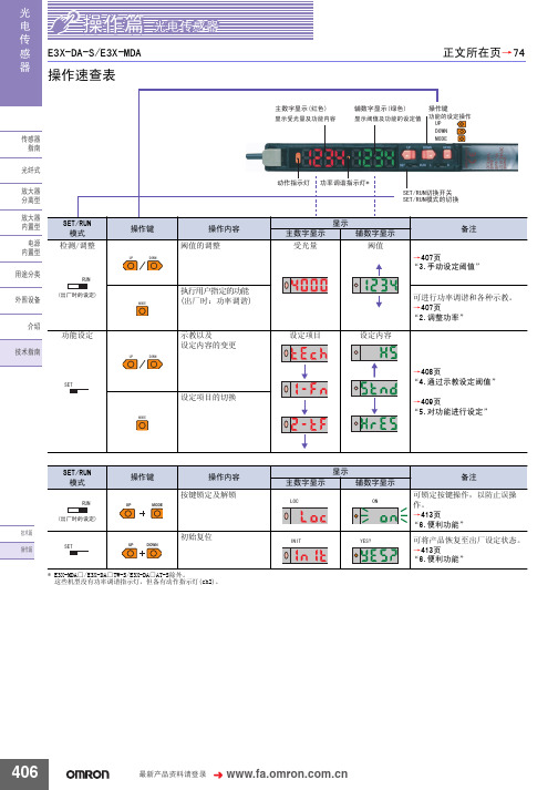
显示 主数字显示
/2&
辅数字显示
21
备注 可锁定按键操作,以防止误操 作。 →413页 “6.便利功能” 可将产品恢复至出厂设定状态。 →413页 “6.便利功能”
UP
MODE
ᡔᴃ㆛ ᪡㆛
6(7
UP DOWN
初始复位
,1,7
<(6"
* E3X-MDA□/E3X-DA□TW-S/E3X-DA□AT-S除外。 这些机型没有功率调谐指示灯,但备有动作指示灯(ch2)。
䗮䖛ᬍ䆒ᅮݙᆍDŽ
ࡳ㛑ৡ鹵
ࡼᓣ Ẕ⌟ࡳ㛑
䆒ᅮݙᆍ ᰒ冫
ܹܝᯊ21˖ǃ䙂ܝᯊ21˖ ᳔ᖿ˖ǃ催䗳˖ǃᷛ˖ޚǃ催㊒ᑺ˖ǃ ᖂߚࡼ˖ ҙ催ࡳ㛑ൟ
E+H电容限位开关FTI51_FTI52
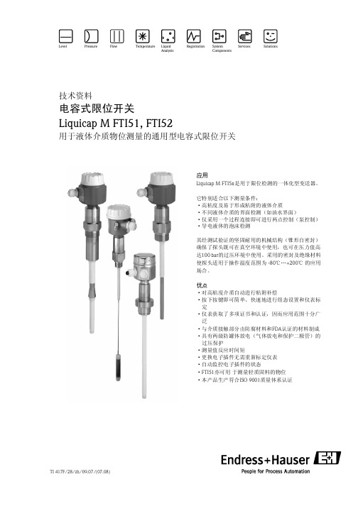
Liquicap M FTI51, FTI52
符合DIN EN 60068-2-64/IEC 68-2-64标准:20…2000Hz,1(m/s2)2/Hz
外壳 清洁过程中务必确保采用的清洁剂不会侵蚀外壳表面或密封件。 探头 应用过程中,探头杆上会有粘附物(污染物和沉积物)生成。严重的粘附现象将影响测量结 果。如果介质易于产生严重的粘附,建议定期清洗探头。清洗过程中,务必确保探头杆的绝缘 层不会被损坏。如果采用清洁剂进行清洗,必需注意材料的相容性!
远程组态设置/诊断 通过HART客户端:
模拟以太网
接口
6
Endress + Hauser
Liquicap M FTI5 1, FTI52
安装指南
操作条件:安装
Liquicap M FTI51(杆式探头)可从上部、下部及侧边进行安装。 Liquicap M FTI52(缆式探头)可从上部垂直进行安装。
(环境温度)
(过程温度)
提示! 仅适用于FTI51! 如果选择了附加选项中的B(防油漆-潮湿损伤),则最低环境温度Ta为-40℃。
10
Endress + Hauser
Liquicap M FTI5 1, FTI52
分离型外壳
(环境温度)
(过程温度)
压力和温度
提示! 探头与分离型外壳间的最大连接长度为6m(L4)。用户订购带分离型外壳的Liquicap M时,必需 提供其要求的连接长度。 如果连接电缆被截短或安装时电缆需穿越墙壁,这时就必需将电缆与过程连接分离安装。
Ф16mm/Ф22mm探头(包括绝缘层) -1…100bar(参考第10页的“过程温度”和第15页的“过程连接”。)
对于通过CRN认证且带屏蔽段的探头最大许可工程压力应≤32bar 在高温条件下使用探头时其许可过程压力值请参考以下标准 ·EN 1092-1:2005表格,附录标准G2 ·ASME B 16.5a-1998表格2-2.2 F316 ·ASME B 16.5a-1998表格2.3.8 N10276 ·JIS B 2220
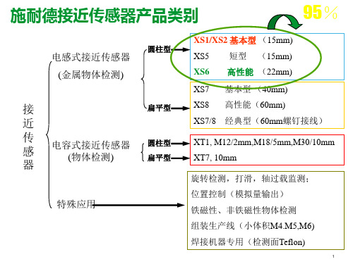
施耐德传感器及安全产品介绍课件
光纤设计
XUX
XUD A2
+ 显示
金属/塑料
金属/塑料
塑料 可选继电器输出
塑料 螺钉接线
自学习模式
26
光电传感器-新XUM卖点及目标行业
产品优势
同类产品中检测距离最长:对射式15m,反射式5m,漫反射式1m NO/NC可调 抗光干扰强度高:自然光40,000LUX/白炽灯10,000LUX 节能增效--同样供电条件下,可使用2倍数量的传感器 防相互干扰:几个传感器可近距离安装同时使用 极具竞争力的价格优势 输出状态指示灯在接收器的前表面,进一步改善安装的统一性 耐环境性能高:-30 到60 ℃的工作温度,防护等级IP67
参数性能。并且注意传感器的输出逻辑形式。
11
XSAV失速保护传感器 性能对比
12
重点产品线XS6*-产品介绍
以最优异的性能满足苛刻的使用要求
➢检测距离:埋入式 2.5-15mm;非埋入式 2.5-22mm;
➢电缆材料:PVR 耐化学腐蚀,耐磨及不宜老化,完全符合阻燃标准 NFC 32-070;
➢电源: DC 10~58V; AC20~264V; ➢输出方式: DC 3线/AC&DC 2线; ➢开关容量:200mA DC;300mA AC;
钢滚轮直动式
XCKJ167H29C WLD2 ZR335-11Z SZL-WL-E TZ5102/TZ5103
直动式
XCKJ10559H29C WLCL Z4V10H335-11Z SZL-WL-C TZ5107
35
限位开关重点产品XCKM-产品介绍
中重载应用
注塑机、纺织机械、印刷机械、物料搬运机械 机床,木工机械,生产线 …
经典型 XCK-J
Omron LS-500 数字激光传感器增强器说明书
241LS-400FIBERSENSORSLASERSENSORSHUMAN MACHINEINTERFACESENERGY CONSUMPTIONVISUALIZATIONCOMPONENTSFA COMPONENTSMACHINE VISIONSYSTEMSUV CURINGSYSTEMSFeaturing stainless steel (SUS) enclosure that won’tbreak when bumped during installation or maintenance.(In STD amplifier response time mode)Unit: mm in Stainless steel (SUS) body 1 m 3.281 ft sensing rangeOne-point M6 installationFeaturing waterproof IP67 to allow use in the presenceof large amounts of water or dust.Two-point installationThe thru-beam type LS-H102 features the same formfactor as the EX-L200 series ultra-compact laser sensorwith built-in amplifier, and it can be used as an EX-L200series with a digital indicator. It also delivers the samebend quality as theEX-L200 series.The LS-H101 features an easy-to-install design.M6Body: Stainless steel(SUS)Operationindicator(receiver only)Actual size1 m 3.281 ft sensing range(In STD amplifier response time mode)The LS-H102 delivers sufficient sensing range for use with450 mm 17.717 in wafers.Check the optimal receiving location at a glance whilewatching the red spot on the beam axis adjustmentscreen.Simple positioningInstallation pitch13 mm 0.512 inEX-L211 / EX-L212LS-H102Same installation pitchas the EX-L200 series Waterproof IP67SEN TRONIC242LS-400FIBER SENSORS PHOTOELECTRIC SENSORS MICROPHOTOELECTRIC SENSORS AREASENSORS LIGHT CURTAINS /SAFETYCOMPONENTS PRESSURE / FLOWSENSORS INDUCTIVE PROXIMITY PLCHUMAN MACHINE INTERFACES ENERGY CONSUMPTION VISUALIZATION COMPONENTS FA COMPONENTS MACHINE VISION SYSTEMSUV CURING SYSTEMSIndustry’s smallest* + Thinnest profile* S mallest amplifier-separated type laser sensor head as of September 2013 based on research conducted by our companyLS-H201Coaxial designSmall, long-range spotEasy-to-see operation indicatorBy using a laser with high linearity in a coaxial design, the LS-H201 is able to deliver stable sensing in confined spaces as well as simple installation.The LS-H201 produces a spot with a diameter of 2 mm 0.079 in at a sensing range of up to 300 mm 11.811 in (in STD amplifier response time mode).The LS-H201’s operation indicator is visible from all directions.Featuring a 60% smaller design (by volume) than previous coaxial reflective models, our smallest unit is smaller in every dimension at just W8 × H23 × D18 mm W0.315 × H0.906 × D0.709 in (excluding indicators).0.315 in23mm ø2 mm ø0.079 in300 mm 11.811 inGasketLS-400FIBER SENSORS PHOTOELECTRICSENSORS MICROPHOTOELECTRICSENSORS AREA SENSORS LIGHT CURTAINS /SAFETY COMPONENTS PRESSURE /FLOW SENSORS INDUCTIVE PROXIMITY SENSORS PARTICULAR USE SENSORSSENSOR OPTIONS SIMPLE WIRE-SAVINGUNITS WIRE-SAVINGSYSTEMS MEASUREMENTSENSORS STATIC ELECTRICITYPREVENTION DEVICES LASER MARKERSPLCHUMAN MACHINEINTERFACES ENERGY CONSUMPTIONVISUALIZATION COMPONENTS FA COMPONENTS MACHINE VISIONSYSTEMS UV CURING SYSTEMSFX-500 series fiber sensor LS-500 series laser sensor0.315 in4 mm 0.157 inAmong industry’s fastest response times* 60 μs* A mplifier-separated type laser sensor amplifiers as ofSeptember 2013 based on research conducted by our company* S mallest amplifier-separated type laser sensor head as ofSeptember 2013 based on research conducted by our companyLS-501□Industry’s smallest* and thinnest designHorizontal symmetryFeaturing a simple system design process thanks to a light source that is placed in the center of the sensor head and a coaxial design.Engineered for maximum compatibility with fiber sensors in every aspect of its design, from form factor to operability, the LS-500 series delivers an environment that makes it easy to choose a laser sensor.The LS-H901 is even thinner than previous models, measuring just W8 × H23 (excluding indicators) × D18 mm W0.315 × H0.906 × D0.709 in .Maximum compatibility with fiber sensorsDetection of beam axis misalignmentDual outputs (self-diagnosis output)Stable sensing over the long term Logic operationsData bankThe LS-500 series features the same operation, menu displays, and form factor as the FX-500 series for increased compatibility with fiber sensors.The LS-500 series can detect any reduction in incident light intensity, for example due to the accumulation of dirt such as dust, and issue an alarm. Sensing output 2 can be set as self-diagnosis output. When you teach the threshold for sensing output 1, sensing output 2 is set accordingly, allowing you to shift the threshold by a previously set margin.The LS-500’s threshold-tracking function helpsmaintain stable sensing over the long term and reduce maintenance man-hours. The incident light intensity can be checked and the threshold automatically reset at a user-selected interval to track changes in light intensity due to environmental changes (such as dust, etc.) over extended periods of time. The LS-500’s ability to perform three logic operations (AND, OR, and XOR) on a standalone basis eliminates the need for a dedicated controller, cuts down onwiring, and lowers costs. This functionality can also be combined with the FX-500 series.Eight sets of amplifier settings can be stored in the unit’s built-in memory. The ability to save and load settings reduces workload when changing the setup in a multi-model production environment.LS-400PHOTO-ELECTRIC SENSORS MICRO PHOTO-ELECTRIC SENSORS AREA SENSORS LIGHT CURTAINS /SAFETY COMPONENTS PRESSURE / FLOW SENSORS INDUCTIVE PROXIMITY SENSORS PARTICULAR USE SENSORS SENSOR OPTIONS SIMPLE WIRE-SAVING UNITS WIRE-SAVING SYSTEMS MEASURE-MENT SENSORS STATIC ELECTRICITY PREVENTION DEVICES LASER MARKERS PLC HUMAN MACHINE INTERFACES ENERGY CONSUMPTION VISUALIZATION COMPONENTSFACOMPONENTS MACHINE VISION SYSTEMSUVCURING SYSTEMSORDER GUIDE056 222 38 18SEN TRONIC AG245Digital Laser Sensor LS-500SERIESLS-400FIBERSENSORSPHOTO-ELECTRICSENSORSMICROPHOTO-ELECTRICSENSORSAREASENSORSLIGHTCURTAINS /SAFETYCOMPONENTSPRESSURE /FLOWSENSORSINDUCTIVEPROXIMITYSENSORSPARTICULARUSESENSORSSENSOROPTIONSSIMPLEWIRE-SAVINGUNITSWIRE-SAVINGSYSTEMSMEASURE-MENTSENSORSSTATICELECTRICITYPREVENTIONDEVICESLASERMARKERSPLCHUMANMACHINEINTERFACESENERGYCONSUMPTIONVISUALIZATIONCOMPONENTSFACOMPONENTSMACHINEVISIONSYSTEMSUVCURINGSYSTEMSSensor head mounting bracketMaterial: Stainless steel (SUS304)Two M3 (length 14 mm 0.551 in)screws with washers [stainlesssteel (SUS304)] are attached.• MS-EXL2-5Fine-Rotatethrough360°Reflector• RF-310• RF-31Reflective tape9.2 mmAccessoriesMS-LS-1 (Sensor head mounting bracket)For LS-H201□ / LS-H901□mountingBack angledmountingRF-330 (Reflector)MS-EXL2-2 (Mounting plate for thru-beam type)Mounting plateMaterial: Stainless steel (SUS304)Two M2 (length 12 mm 0.472 in) screws with washers[stainless steel (SUS)] are attached.Material: Stainless steel (SUS)Material: Die-cast zinc alloyTwo M3 (length 14 mm 0.551 in) screws withwashers [stainless steel (SUS)], one M3 (length 10mm 0.394 in) hexagon-socket-head bolt [stainlesssteel (SUS)], and one M3 hexagon nut [stainlesssteel (SUS)] are attached.0.551 in) screws withwashers [stainless steel (SUS)] are attached.056 222 38 18*********************SEN TRONICAG246Digital Laser SensorLS-500SERIESLS-400FIBER SENSORS PHOTO-ELECTRIC SENSORS MICRO PHOTO-ELECTRIC SENSORS AREA SENSORS LIGHT CURTAINS /SAFETY COMPONENTS PRESSURE / FLOW SENSORS INDUCTIVE PROXIMITY SENSORS PARTICULAR USE SENSORS SENSOR OPTIONS SIMPLE WIRE-SAVING UNITSWIRE-SAVING SYSTEMS MEASURE-MENT SENSORS STATIC ELECTRICITY PREVENTION DEVICES LASER MARKERS PLC HUMAN MACHINE INTERFACES ENERGY CONSUMPTION VISUALIZATION COMPONENTS FACOMPONENTSMACHINE VISION SYSTEMS UVCURING SYSTEMSNotes: 1) Where measurement conditions have not been specified precisely, the conditions used were an ambient temperature of +23 °C +73.4 °F . 2) When using the thru-beam type LS-H101□ or LS-H102□, do not set the receiving light sensitivity (gctL) of the applicable LS-500 series amplifier to level2 or less. This is because there is a possibility of sensing becoming unstable.3) The sensing range of the coaxial reflective type sensor is specified for white non-glossy paper (100 × 100 mm 3.937 × 3.937 in ) as the object. 4) The sensing ranges for coaxial retroreflective type sensors are values for the RF-330 reflector. In addition, the sensing range is the possible settingrange for the reflector. The sensor can detect an object less than 0.01 m 0.033 ft away. Note that if there are white papers or specular objects near the sensor head, reflected light from these objects may be received. In such cases, use the amplifier unit’s receiving sensitivity function to lower thesensitivity, change the response time, or move the sensor head away from the target object. The incident light intensity may vary with the condition of the reflector surface. When using one of the applicable LS-500 series amplifiers, leave an adequate safety margin when setting the threshold.5) Make sure to confirm detection with an actual sensor before use. 6) This product complies with 21 CFR 1040.10 and 1040.11 Laser Notice No. 50, dated June 24, 2007, issued by CDRH (Center for Devices andRadiological Health) under the FDA (Food and Drug Administration). For details, refer to the Laser Notice No. 50.7) Cable cannot be extended.056 222 38 18*********************SEN TRONIC AG247Digital Laser Sensor LS-500SERIESLS-400FIBERSENSORSPHOTO-ELECTRICSENSORSMICROPHOTO-ELECTRICSENSORSAREASENSORSLIGHTCURTAINS /SAFETYCOMPONENTSPRESSURE /FLOWSENSORSINDUCTIVEPROXIMITYSENSORSPARTICULARUSESENSORSSENSOROPTIONSSIMPLEWIRE-SAVINGUNITSWIRE-SAVINGSYSTEMSMEASURE-MENTSENSORSSTATICELECTRICITYPREVENTIONDEVICESLASERMARKERSPLCHUMANMACHINEINTERFACESENERGYCONSUMPTIONVISUALIZATIONCOMPONENTSFACOMPONENTSMACHINEVISIONSYSTEMSUVCURINGSYSTEMS2) 25 mA if 5 or more amplifier are connected in cascade (excluding cable extension).3) Number of units that can be mounted close together: 0 for H-SP; 2 for FAST; 4 for STD, LONG, U-LG, or HYPR4) Select either sensing output 2 or external input as the connector type.056 222 38 18*********************SEN TRONICAG248Digital Laser SensorLS-500SERIESLS-400FIBER SENSORS PHOTO-ELECTRIC SENSORSMICRO PHOTO-ELECTRIC SENSORS AREA SENSORSLIGHTCURTAINS /SAFETY COMPONENTSPRESSURE /FLOW SENSORS INDUCTIVE PROXIMITY SENSORSPARTICULAR USE SENSORS SENSOR OPTIONS SIMPLE WIRE-SAVING UNITS WIRE-SAVING SYSTEMS MEASURE-MENT SENSORS STATIC ELECTRICITY PREVENTION DEVICES LASER MARKERS PLCHUMAN MACHINE INTERFACES ENERGY CONSUMPTION VISUALIZATION COMPONENTS FACOMPONENTSMACHINE VISION SYSTEMS UVCURING SYSTEMSSymbols ...D 1, D 2, D 3, D 4: Reverse supply polarity protection diodeZ D1, Z D2: Surge absorption zener diode Tr 1, Tr 2 : NPN output transistor%Notes: 1) The quick-connection sub cable does not have +V (brown) and 0 V (blue).The power is supplied from the connector of the main cable.2) Wiring when sensing output 2 is selected is shown with solid lines. Wiringwhen external input is selected is shown with broken lines.NPN output typeConnector typeCable typeI/O circuit diagramsNPN output typePNP output typeNotes: 1) The quick-connection sub cable does not have brown lead wire and blue leadwire. The power is supplied from the connector of the main cable.2) The quick-connection cable does not have gray or pink lead wires.Wiring diagramsTerminal layout of connector typeColor code of cable type / quick-connection cable Color code of cable type / quick-connection cable Notes: 1) The quick-connection sub cable does not have brown lead wire and blue leadwire. The power is supplied from the connector of the main cable.2) The quick-connection cable does not have gray or pink lead wires.* Connector for amplifier (CN-EP4) pin position%%Notes: 1) The quick-connection sub cable does not have +V (brown) and 0 V (blue).The power is supplied from the connector of the main cable.2) Wiring when sensing output 2 is selected is shown with solid lines. Wiringwhen external input is selected is shown with broken lines.%%%PNP output typeConnector typeCable typeSymbols ...D 1, D 2, D 3, D 4: Reverse supply polarity protection diodeZ D1, Z D2: Surge absorption zener diode Tr 1, Tr 2 : PNP output transistor056 222 38 18*********************SEN TRONIC AG249Digital Laser Sensor LS-500SERIESLS-400FIBERSENSORSPHOTO-ELECTRICSENSORSMICROPHOTO-ELECTRICSENSORSAREASENSORSLIGHTCURTAINS /SAFETYCOMPONENTSPRESSURE /FLOWSENSORSINDUCTIVEPROXIMITYSENSORSPARTICULARUSESENSORSSENSOROPTIONSSIMPLEWIRE-SAVINGUNITSWIRE-SAVINGSYSTEMSMEASURE-MENTSENSORSSTATICELECTRICITYPREVENTIONDEVICESLASERMARKERSPLCHUMANMACHINEINTERFACESENERGYCONSUMPTIONVISUALIZATIONCOMPONENTSFACOMPONENTSMACHINEVISIONSYSTEMSUVCURINGSYSTEMSMetal plateAccessory forMS-EXL2-1Cautions for laser beamsPart description (Amplifier)MountingAmplifierLS-H201□, LS-H901□<How to mount the amplifier>(1) F it the rear part of the mountingsection of the amplifier on a 35 mm1.378 in width DIN rail.(2) P ress down the rear part of themounting section of the unit on the 35 mm 1.378 in widthDIN rail and fit the front part of the mounting section tothe DIN rail.<How to mount the sensor head>(1) I nsert the sensor headconnector into the inlet until itclicks.(2) Fit the cover to the connector.<How to remove the amplifier>(1) Push the amplifier forward.(2) L ift up the front part of theamplifier to remove it.Note: B e careful. If the front part is lifted without pushing the amplifier forward,Sensor headLS-H101□• The tightening torqueshould be 0.98 N·m or less.LS-H102□• In case mounting this product,use a metal plate MS-EXL2-2(accessory).• The tightening torque should be0.5 N·m or less with M3 screws.<Not requiring the metal plate><Requiring the metal plate>• In case using the dedicated sensor head mountingbracket MS-EXL2-1 (optional) when mounting thisproduct, the metal plate MS-EXL2-2 (accessory) isrequired depending on the mounting direction. Mount asthe diagram below indicates.• The tightening torqueshould be 0.5 N·m orless.• When placing the sensorhead horizontally orvertically, the reflectormust also be positionedhorizontally or verticallyas shown in Fig. 1 below. I f the sensor head is placed horizontallyor vertically but the reflector is tilted as shown in Fig. 2 below, thereflection amount will decrease, which may cause unstable detection.Safety standards for laser beam products• A laser beam can harm human being’s eyes, skin, etc.,because of its high energy density. IEC has classifiedlaser products according to the degree of hazard and thestipulated safety requirements. LS-H□ is classified asClass 1 laser.Classification by IEC 60825-1width DIN railconnector(Purchase separately)Safe use of laser products• For the purpose of preventing users from sufferinginjuries by laser products, IEC 60825-1 (Safety of laserproducts). Kindly check the standards before use.(Refer to About laser beam.)* T his product complies with 21 CFR 1040.10 and 1040.11 Laser NoticeNo. 50, dated June 24, 2007, issued by CDRH (Center for Devices andRadiological Health) under the FDA (Food and Drug Administration).056 222 38 18*********************SEN TRONICAG250Digital Laser SensorLS-500SERIESLS-400FIBER SENSORS PHOTO-ELECTRIC SENSORS MICRO PHOTO-ELECTRIC SENSORS AREA SENSORS LIGHT CURTAINS /SAFETY COMPONENTS PRESSURE / FLOW SENSORS INDUCTIVE PROXIMITY SENSORS PARTICULAR USE SENSORS SENSOR OPTIONS SIMPLE WIRE-SAVING UNITS WIRE-SAVING SYSTEMS MEASURE-MENT SENSORS STATIC ELECTRICITY PREVENTION DEVICES LASER MARKERS PLC HUMAN MACHINE INTERFACESENERGY CONSUMPTION VISUALIZATION COMPONENTS FACOMPONENTSMACHINE VISION SYSTEMS UVCURING SYSTEMSFig. 1 Proper positioningWhen placing the sensor head horizontally or vertically, the reflector shall also be positioned horizontally or vertically.Fig. 2 Improper positioningWhen placing the reflector tilted even when the sensor head is positioned horizontally or vertically.Wiring• Make sure that the power supply is off while wiring.• Verify that the supply voltage variation is within the rating.• Take care that if a voltage exceeding the rated range is applied, or if an AC power supply is directly connected, the sensor may get burnt or damaged.• If power is supplied from a commercial switching regulator, ensure that the frame ground (F.G.) terminal of the power supply is connected to an actual ground.• Make sure to use the optional quick-connection cable for the connection of the amplifier [connector type LS-501(P )]. Extension up to total 100 m 328.084 ft is possible with 0.3 mm 2, or more, cable. However, in order to reduce noise, make the wiring as short as possible. Set the supply voltage after considering the voltage drop caused by the cable’s resistance.Others• Do not use during the initial transient time (0.5 sec. approx.) after the power supply is switched on.• B ecause the sensitivity is higher in U-LG and HYPER modes than in other modes, it can be more easily affected byextraneous noise. Check the operating environment before use.Amplifier LS-501 LS-501PAmplifierLS-501-C LS-501P-CCN-74-C1 CN-74-C2 CN-74-C5Main cable (Optional)Sub cable (Optional)CN-72-C1 CN-72-C2 CN-72-C5When adding units, wiring length must not exceed 50 m 164.042 ft (for 5 to 8 amplifiers) or 20 m 65.617 ft (for 9 to 16 amplifiers). <Correct><Incorrect>056 222 38 18*********************SEN TRONIC AG251Digital Laser Sensor LS-500SERIESLS-400FIBERSENSORSPHOTO-ELECTRICSENSORSMICROPHOTO-ELECTRICSENSORSAREASENSORSLIGHTCURTAINS /SAFETYCOMPONENTSPRESSURE /FLOWSENSORSINDUCTIVEPROXIMITYSENSORSPARTICULARUSESENSORSSENSOROPTIONSSIMPLEWIRE-SAVINGUNITSWIRE-SAVINGSYSTEMSMEASURE-MENTSENSORSSTATICELECTRICITYPREVENTIONDEVICESLASERMARKERSPLCHUMANMACHINEINTERFACESENERGYCONSUMPTIONVISUALIZATIONCOMPONENTSFACOMPONENTSMACHINEVISIONSYSTEMSUVCURINGSYSTEMSLS-H101□Sensor headNote: Not incorporated on the emitter.Sensor headLS-H102□Note: Not incorporated on the emitter.LS-H201□ LS-H901□Sensor head3.156.90.8MS-DIN-E End plate (Optional)Material: Acrylic (Reflector)ABS (Base)0.1650.217Reflector (Accessory for LS-H901□)RF-330Material: Acrylic (Reflector)ABS (Base)RF-310Reflector (Optional)Reflective tape (Optional)RF-33 RF-318.5Material: Cold rolled carbon steel (SPCC)(Uni-chrome plated)MS-DIN-2Amplifier mounting bracket (Optional) 056 222 38 18*********************SEN TRONICAG252Digital Laser SensorLS-500SERIESLS-400FIBER SENSORS PHOTO-ELECTRIC SENSORS MICRO PHOTO-ELECTRIC SENSORS AREA SENSORS LIGHT CURTAINS /SAFETY COMPONENTS PRESSURE / FLOW SENSORS INDUCTIVE PROXIMITY SENSORS PARTICULAR USE SENSORS SENSOR OPTIONS SIMPLE WIRE-SAVING UNITS WIRE-SAVING SYSTEMS MEASURE-MENT SENSORS STATIC ELECTRICITY PREVENTION DEVICES LASER MARKERSPLC HUMAN MACHINE INTERFACES ENERGY CONSUMPTIONVISUALIZATION COMPONENTSFACOMPONENTS MACHINE VISION SYSTEMS UVCURING SYSTEMSRear mounting bracketFoot angled mounting bracketUniversal sensor mounting bracketAssembly dimensionsMaterial: Stainless steel (SUS304)Two M3 (length 14 mm 0.551 in ) screws with washers [stainless steel (SUS304)] are attached.Material: Stainless steel (SUS304)Note: Without using the mounting plate,beam misalignment may occur.Mounting drawing with the emitter of LS-H102□Assembly dimensionsMounting drawing with the receiver of LS-H102□Note: Screws are not attached. Purchase separately.0.0590.0390.10233-M3 × 0.5 14 Note: This is the adjustable range of the movable part.Mounting drawing with the receiver of LS-H102□112 8 R13 t 1.5 MS-LS-1Sensor head mounting bracket (Accessory for LS-H201□, LS-H901□)Sensor head mounting bracket for LS-H102□ (Optional)MS-EXL2-1MS-EXL2-2Mounting plate (Accessory for LS-H102□)Sensor head mounting bracket for LS-H102□ (Optional)MS-EXL2-4Sensor head mounting bracket for LS-H102□ (Optional)MS-EXL2-5Material: Stainless steel (SUS304)Two M3 (length 14 mm 0.551 in ) screws with washers [stainless steel (SUS304)] are attached.Material: Die-cast zinc alloyTwo M3 (length 14 mm 0.551 in ) screws with washers, one M3 (length 10 mm 0.394 in ) hexagon socket-head bolt [stainless steel (SUS)], and one M3 hexagon nut [stainless steel (SUS)] are attached.056 222 38 18*********************SEN TRONIC AG。
欧姆龙光电开关说明书
欧姆龙光电开关说明书1. 引言欧姆龙光电开关是一种利用光电传感器技术实现的开关设备,通过检测光线的变化来判断是否触发开关动作。
本说明书将详细介绍欧姆龙光电开关的技术原理、使用方法、注意事项以及维护保养等内容,以帮助用户合理、安全地使用该设备。
2. 技术原理欧姆龙光电开关采用了光电传感器技术,在光电传感器中,包含了一对光源和光敏元件。
当遮挡物体经过检测区域时,光敏元件将接收到的光信号发生变化,从而触发开关动作。
光电开关通常有两种工作方式:逻辑输出和模拟输出,具体的输出信号可以根据用户需求进行设置。
3. 使用方法a)安装根据实际需求,将光电开关安装到需要检测的位置上,确保光敏元件可以正常接收到被检测物体通过的光信号。
注意避免外部光源对光敏元件产生干扰,可以通过合理选择安装位置和使用遮光罩等方式来减少干扰。
b)连接将光电开关与电路连接,确保电路连接正确且稳定。
通常光电开关需要使用直流电源进行供电,电压范围根据具体型号来确定。
c)设置根据实际应用需求,设置光电开关的工作方式、触发灵敏度等参数。
欧姆龙光电开关通常提供了相应的参数调节装置,用户可以根据需要进行调整。
d)测试完成安装、连接和设置后,进行测试以确保光电开关正常工作。
可以通过手动触发被检测物体通过检测区域,观察开关的触发情况,根据实际需求进行调整。
4. 注意事项a)使用过程中请确保电源电压符合设备要求,避免超过额定电压范围。
b)在使用过程中请避免将光电开关安装在高温、潮湿等有害环境中,以免影响设备的正常工作。
c)避免遮挡光敏元件,在使用过程中请确保光敏元件处于正常工作状态,避免被阻挡物体遮挡。
d)避免外部光源干扰,在安装过程中请注意避免强光直射到光敏元件上,可以使用遮光罩等方式来减少光源干扰。
e)检查设备连接是否牢固,确保所有连接处都紧固可靠,避免松动引起的工作异常。
f)如设备出现故障,请及时联系专业维修人员进行处理,避免私自拆解修理。
5. 维护保养a)定期清洁光敏元件,可以使用干净的棉签轻轻擦拭。
OMRON 限位开关 说明书
聚酰胺(尼龙)树脂
开关盒 密封橡胶
聚苯硫醚 铝(铸件) 锌(铸件)
丁腈橡胶
硅胶 氟化胶 氯丁二烯橡胶
材料记号 Au AuAg PGS AgPd
Ag
AgNi AgInSn C5210 C1700 C1720 C1700-□M C1720-□M SUS301-CSP SUS304-CSP PF PBTP PETP
接触形式 根据各种用途构成接点的电气输入输出电 路的方式。 树脂固定 (塑封端子) 用导线对端子部分完好配线, 通过充填树 脂使该部分固定, 消除暴露在外的带电部 分, 提高密封性的一种方法。
⚍ ᣛৃࡼ⠛ড䕀ᯊ㾺 ࠄⱘ䞥ሲ䚼ߚˈ䗮䖛 䖭辵㾺ᴹᅲ⦄⬉⇨ 䗮ǃᮁⱘϔ辵䳊ӊDŽ
⚍䯈䱨 ᣛᅮ⚍ৃࡼ⚍ ⱘ䯈䱨ǃ⚍鼠ࡼⱘ䎱 行DŽ
■EN60947-5-1规格用语
对目录中使用的上述规格用语说明如下。
ᓔ݇ ⎆ԡ䆒
⎆ԡ䆒 ᖂࡼᓔ݇ 䰤ԡᓔ݇ ᣝ䪂ᓔ݇ ᢼⷕᢼࡼᓔ݇ 䕏㾺ᓣᓔ݇ 㠍ൟᓔ݇ ᭄ᄫᰒ冫
ऩܗ
ᡔᴃᣛफ
EN60947-5-1 「电气机械控制电路设备」的EN规格。 和IEC60947-5-1的内容相同。 使用范围 开关按用途来分类。 请参考下面的例子。
(1)活塞型 根据密封方法不同,有表中的A型和B型2个种类。 A型是用O型环 或薄膜密封的,由于密封橡胶没有外露,在抵制工作机械的切割碎 屑方面功能较强大,但其反面影响是,有可能会将砂子、切割粉末 等压入活塞的滑动面。B型虽然不会把砂子、切割粉末等压入,且 密封性能优于A型,但由于炽热的切割碎屑飞溅过来,有可能会损 坏橡胶帽。因此,要根据使用场所的不同选用A型或B型。而柱塞 型仍然通过柱塞的往复运动压缩或吸进空气。 为此,如果长时间将柱塞压入,限位开关内的压缩空气逸失,内部 压力将与大气压相同,即使急于让柱塞复位,柱塞却有迟缓复位的 倾向。为了避免发生这种故障,设计时请参见199页。
行程开关欧姆龙hl-5030
行程开关欧姆龙hl-5030
接近开关是一种无需与运动部件进行机械直接接触而可以操作的位置开关,当物体接近开关的感应面到动作距离时,不需要机械接触及施加任何压力即可使开关动作,从而驱动直流电器或给计算机(plc)装置提供控制指令。
接近开关是种开关型传感器(即无触点开关),它既有行程开关、微动开关的特性,同时具有传感性能,且动作可靠,性能稳定,频率响应快,应用寿命长,抗干扰能力强等、并具有防水、防震、耐腐蚀等特点。
产品有电感式、电容式、霍尔式、交、直流型。
接近开关又称无触点接近开关,是理想的电子开关量传感器。
当金属检测体接近开关的感应区域,开关就能无接触,无压力、无火花、迅速发出电气指令,准确反应出运动机构的位置和行程,即使用于一般的行程控制,其定位精度、操作频率、使用寿命、安装调整的方便性和对恶劣环境的适用能力,是一般机械式行程开关所不能相比的。
它广泛地应用于机床、冶金、化工、轻纺和印刷等行业。
在自动控制系统中可作为限位、计数、定位控制和自动保护环节等。
行程开关欧姆龙hl-5030。
- 1、下载文档前请自行甄别文档内容的完整性,平台不提供额外的编辑、内容补充、找答案等附加服务。
- 2、"仅部分预览"的文档,不可在线预览部分如存在完整性等问题,可反馈申请退款(可完整预览的文档不适用该条件!)。
- 3、如文档侵犯您的权益,请联系客服反馈,我们会尽快为您处理(人工客服工作时间:9:00-18:30)。
OMRON限位开关hl-5050
接近开关是一种无需与运动部件进行机械直接接触而可以操作的位置开关,当物体接近开关的感应面到动作距离时,不需要机械接触及施加任何压力即可使开关动作,从而驱动直流电器或给计算机(plc)装置提供控制指令。
接近开关是种开关型传感器(即无触点开关),它既有行程开关、微动开关的特性,同时具有传感性能,且动作可靠,性能稳定,频率响应快,应用寿命长,抗干扰能力强等、并具有防水、防震、耐腐蚀等特点。
产品有电感式、电容式、霍尔式、交、直流型。
接近开关又称无触点接近开关,是理想的电子开关量传感器。
当金属检测体接近开关的感应区域,开关就能无接触,无压力、无火花、迅速发出电气指令,准确反应出运动机构的位置和行程,即使用于一般的行程控制,其定位精度、操作频率、使用寿命、安装调整的方便性和对恶劣环境的适用能力,是一般机械式行程开关所不能相比的。
它广泛地应用于机床、冶金、化工、轻纺和印刷等行业。
在自动控制系统中可作为限位、计数、定位控制和自动保护环节等。
OMRON限位开关hl-5050。