集和诚嵌入式工控机FEBC-3575
利泰恒通 LT-A2410A 嵌入式 RISC 控制板及开发系统套件 使用说明书

LT—A2410 A型嵌入式RISC控制板及开发系统套件使用说明书北京利泰恒通科技发展有限公司一、 简述LT—2410A我公司最新设计的,是采用SAMSUNG2410(ARM9内核)作为微处理器的嵌入式RISC控制板,外形为标准的3.5吋嵌入式主板的设计形式,同时采用底板与核心板分离的设计架构,便于用户扩展,固定可靠,可直接应用在工业、医疗、网络、智能终端,特别是音/视频处理等嵌入式设备的设计和制造中,同时也可作为上述产品的开发、评估及测试使用。
1、系统简述SAMSUNG2410是一款16-32位精减指令(RISC)微处理器,采用ARM920T内核,主频高达400—533MHZ。
处理器本身支持虚拟内存单元管理(MMU)、NAND/NOR FLASH 启动、SDRAM管理、LCD驱动。
同时支持4通道DMA、3通道UART、4路定时器、RTC 实时时钟、IIC总线接口、IIS数字音频接口、8路10位AD及多路I/O控制。
此外,同时支持多路USB主从设备、SPI总线。
是一款速度块、高集成、底功耗的嵌入式处理器。
LT—2410A是以该款处理器为核心的核心板,扩展了形成了最小的核心系统,使之可具备各种用户所需要的通用功能,使用户可以以此为基础,根据需要自行开发扩展板,快速开发出相应的产品。
也可直接将LT—2410A嵌入应用到产品当中,已缩短开发时间。
2、技术特性处理器:S3C2410 处理器,32 位处理器,203MHz内存: 64MB SDRAM64MB NandFlash(或16MB NorFlash)-最高支持12.1寸TFT 800*600 64K色LCD以及触摸屏-10M以太网接口(10/100M可选)-3通道UART(支持IRDA红外线数据通讯口)-4个USB主机接口及1个USB设备接口-SD卡控制器接口-Embedded-ICE调试接口-RTC实时时钟(具备后备锂电池)-IIC总线接口(驱动AT24C04-SC27)-ADC模数转换接口-SPI接口-IIS数字音频输入/输出接口-EINT外部中断接口二、 配置说明LT—A2410A开发套件分为由以下几部分组成:1、LT—2410A 嵌入式控制板一块2、显示部件一套,其中包括:(1)10.4吋TFT液晶一块,分辨率为640*480。
AD421中文资料
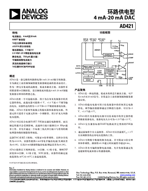
这款DAC采用Σ-Δ架构,可保证16位单调性,且积分非线 性为±0.01%。该器件提供4 mA零电平输出电流(失调误差 为±0.1%),以及20 mA满量程输出电流(增益误差为±0.2%)。
单位
条件/注释
精度 分辨率 单调性 积分非线性 失调(4 mA)(+25°C时)4 失调漂移 典型输出误差(20 mA) (+25°C时)4 总输出漂移 VCC电源灵敏度
16 16 ± 0.01 ± 0.1 ± 25 ± 0.2 ± 50 50
位 位(最小值) % FS(最大值) % FS(最大值) ppm FS/°C(最大值) % FS(最大值) ppm FS/°C(最大值) nA/mV(最大值)
FS = 满量程输出电流 VCC = 5 V 包括片内基准电压漂移 VCC = 5 V 包括片内基准电压漂移 25 nA/mV(典型值)
基准电压源 REF OUT2 输出电压 温漂
外部电流 VCC电源灵敏度 输出阻抗 噪声(0.1 Hz–10 Hz) REF OUT1
输出电压 温漂
外部电流 VCC电源灵敏度 输出阻抗 噪声(0.1 Hz–10 Hz) REF IN 输入电阻
7. AD421具有可编程报警电流功能,允许发射器通过发 送超量程电流来指示传感器故障。
HART是HART通信基金会的注册商标。
Rev. C
Information furnished by Analog Devices is believed to be accurate and reliable. However, no responsibility is assumed by Analog Devices for its use, nor for any infringements of patents or other rightsofthirdpartiesthatmayresultfromitsuse.Speci cationssubjecttochangewithoutnotice.No license is granted by implication or otherwise under any patent or patent rights of Analog Devices. Trademarks and registered trademarks are the property of their respective owners.
amaran P60c 产品说明书

amaran P60c Product ManualThank you for purchasing the amaran series LED photography light-amaran P60c.ForewordThe amaran P60c is a RGBWW full-color adjustable panel photography light with adjustable temperature (2500 K - 7500 K), power of 60w, and maximum illuminance of 5900 lux@1 m (5600 K). The P60c is also excellent in terms of light quality, with a color rendering index of up to CRI 95+, TLCI 97, G/M adjustable and no flicker at all.The amaran P60 series is creators' best choice because of its feature of lightweight and flexibility.IMPORTANT SAFETY INSTRUCTIONSWhen using this unit, basic safety precautions should always be followed, including the following:Read and understand all instructions before using.Close supervision is necessary when any fixture is used by or near children. Do not leave the fixture unattended while in use.Care must be taken as burns can occur from touching hot surfaces.Do not operate the fixture if a cord is damaged, or if the fixture has been dropped or damaged, until it has been examined by qualified service personnel.Position any power cables such that they will not be tripped over, pulled, or put into contact with hot surfaces.If an extension cord is necessary, a cord with an amperage rating at least equal to that of the fixture should be used. Cords rated for less amperage than the fixture may overheat.Always unplug the lighting fixture from the electrical outlet before cleaning and servicing, or when not in use. Never yank the cord to remove the plug from the outlet.Let the lighting fixture cool completely before storing.To reduce the risk of electric shock, do not immerse this fixture in water or any other liquids. 1.2.3.4.5.6.7.8.9.10.To reduce the risk of re or electric shock, do not disassemble this fixture. ************************************fiedservicepersonnelwhen service or repair work is required. Incorrect reassembly may cause electric shock when the lighting fixture is in use.11.12.13.14.15.16.17.18.19.The use of an accessory attachment not recommended by the manufacturer may increase the risk of re, electric shock, or injury toany persons operating the fixture.Power this fixture by connecting it to a grounded outlet.Please do not place the LED lighting fixture near any flammable object. Only use a dry microfiber cloth to clean the product.Please have the product checked by an authorized service personnel agent if your product has a problem.The malfunctions caused by unauthorized disassembly are not covered under the warranty.We recommend only using the original Aputure cable accessories. Please note that our warranty for this product does not apply to any repairs required due toany malfunctions of unauthorized Aputure accessories, although you may request such repairs for a fee.This product is certified by RoHS, CE, KC, PSE, and FCC. Pleaseoperate the product in full compliance with the operation standards. Please note that this warranty does not apply to repairs arising from malfunctions, although you may request such repairs on a chargeable basis.The instructions and information in this manual are based on thorough, controlled company testing procedures. Further notice will not be given if the design or specifi cations change.SAVE THESE INSTRUCTIONSFCC compliance statementThis device complies with Part 15 of the FCC rules. The operating equipment must meet the following two conditions:(1) This device will not cause harmful interference;(2) This device can withstand any external interference, including interference that may cause unintended operation.[Warning] If the user makes changes or modifications without the express permission of Aitus, he may lose the right to continue to operate the device. [Note] This device has been tested and determined to comply with the limits of a Class B digital device (in accordance with Part 15 of the FCC rules).These limits are designed to provide reasonable protection from harmful interference in residential installations. This device generates, uses, andcan radiate radio frequency energy. If it is not installed and used in accordance with the instructions, it may cause harmful interference toradio communications. However, under certain installation conditions, there is no guarantee that such interference will not occur. If this equipment does cause harmful interference to radio or television reception, and this can be determined by turning off and on the equipment, it is recommended that the user try one or more of the following measures to eliminate the interference:Increase the distance between the equipment and the receiver.Connect the equipment to an outlet on another circuit, not the outlet on the circuit to which the receiver is connected.Consult the dealer or an experienced radio/TV technician for helpFCC radiation exposure statementThis device complies with FCC radiation exposure limits for uncontrolled environments.Componets Listamaran P60cAdapter1/4 - 20 in & 3/8 -16 inSpigot SoftboxGridProduct Details LED chipsLens protectivebaffle Softboxsupporthandle1/4 screw hole 1/4 screw holeOLED Display CCT/HUE WheelDC Input G/M / SATWheel MENU ButtonLIGHT Mode ButtonPreset ButtonsINT WheelPower ButtonNP-F batteryslotInstallation3. Install the soft box to the lamp body4. The grid can be installed according to the requirementsPower supply1. Adapter power supply* D-tap to DC cable needs to be purchased separately.Through the "D-tap to DC" connection cable, the lamp body can be connected to the V-mount battery or Anton Bauer battery for power supply.2. Manual Control Rotate the Intensity (INT) Wheel to adjust the intensity of the light from 0-100%.Rotate the CCT / HUE wheel to adjust the CCT of the light from2500K-7500K.Rotate the Green-Magenta / Saturation (G/M / SAT) Wheel to adjust the the Green-Magenta Shift or Saturation output of thelight fixture.* The speed at which you rotate the knob will result in different rates of change.2.2 Light Mode Interface2.2.1 Press the INT wheel toselect CCT mode to adjust thecolor temperature of the lightfrom 2500 K - 7500 K.2.2.2 Press the Light Mode buttonto enter the main interface, pressthe INT wheel to select HSI modeto adjust the change of the HUEfrom 1°- 360°. SAT from 0% -100%.2.2.3 Press the Light Mode buttonto enter the main interface , pressthe INT wheel to select FX mode,then rotate the INT wheel to togglebetween Lightning, Paparazzi,Strobe, Cop Car, Fireworks , Pulsing,Fault Bulb, Fire, TV , Party Lights,.Lightning PaparazzStrobe FireworksPulsingCop carFaulty Bulb TVParty lightsFire2.24 Short press the INT wheel to enter or exit the light effect cycle, the icon is ( ) in the cycle state, and the icon is ( ) when the light effect is in the stop state; short press the INT wheel in the lightning mode (Lightning) to start a single Second trigger function, long press the INT wheel to perform cycle function ( ).2.25 Short press INT to select the GEL mode, turn the INT wheel to adjust the brightness, turn the color temperature wheel to select 3200 K / 5600 K, and turn the G/M wheel to select the color papermodel, and the light will be emitted synchronously corresponding to the filter paper effect.2.3 Press the MENU button to enter the menu interface.3. Menu introduction3.1 Fan ModePress the MENU button to enter the menu interface, rotate the INT wheel to select and press to enter the Fan mode, rotate the INT wheel to select the smart/medium mode, and then short press the INT wheel to confirm the selection.MENU3.2 Freq. SelectionPress the MENU button to enter the menu interface, rotate the INT wheel to select and press to enter the Frequency Selection interface. Rotate the INT wheel to adjust the light frequency by 100Hz every turn.3.3 BT ResetPress the MENU button to enter the menu interface, rotate the INT wheel to select and press to enter the Bluetooth Reset. Rotate the INT wheel to select "YES" to reset the Bluetooth pairing; If you choose “NO”, then it will return to the previous menu.3.4 BT Serial No.Press the MENU button to enter the menu interface, rotate the INT wheel to select and press to enter the Fixture Serial No.and you can see that device has a unique serial number.3.5 Studio ModePress the MENU button to enter the menu interface, rotate the INT wheel to select and press to enter the Studio mode interface. Rotate the INT wheel to select "Yes", and the power-on light is on.3.6 LanguagePress the MENU button to enter themenu interface, rotate the INT wheel to select and press to enter the Language menu. You can rotate the INT wheel to select English or Chinese, and then press the Select wheel to confirm the selection.3.7 Firmware VersionPress the MENU button to enter themenu interface, rotate the INT wheel to select and press to enter the Firmware Version, You can check the firmware version number of the fixture.3.8 Factory ResetPress the MENU button to enter the menu interface, rotate the INT wheel to select and press to enter Press the MENU button to enter the Factory Reset interface You can rotate the INT wheel to select "YES" . back to the factory settings.3.9 Custom FXPress the MENU button to enter themenu interface, rotate the INT wheel to select and press to enter the Custom FX. You can choose to enter Picker FX, Music FX, or Touchbar FX interface. Each type can save 10 custom FXs. In the name of each FX, "NO FX" means unsaved FX, and "Untitled" means saved FX.3.10 ExitPress the MENU button to enter the menu mode, rotate and short press the INT wheel to select exit, you can return to the initial interface of CCT mode.3.11 Preset functionThere are 4 preset buttons located on the bottom row of the control box. Once you have set your light to the desired output, long press and hold one of the four buttons (1, 2, 3, or 4) to start the Save Preset procedure. Use the INT control wheel to select "YES" or "NO".You can then use those preset buttons in any Lighting Mode and it will activate the mode and settings you previously saved to that preset. You can save a nearly infinite number of presets using the Sidus Link mobile app.4. Use of Sidus Link APPYou can search for sidus link in App store and Android market to download professional control software to control Aitus lamps. For more detailed usage, please visit: sidus.link/app/helpSpecificationsCCTCRITLCICQSSSI (D56)SSI (D32)Beam anglePower OutputPower InputOperating Current Operating VoltageNP-F Battery Operating Voltage V/Anton Bauer Mount Battery Operating Voltage Operating temperature Control MethodsWireless Operating Range (Bluetooth)Screen TypeCooling MethodHead CablePower cableLamp Head SizeLamp Head Weight 2500 K - 7500 K≥ 95≥ 96≥ 96≥ 74≥ 8345°≤ 60 W≤ 78 W4.5 A100 V - 240 V 50 Hz / 60 Hz 6.5 V - 8.4 V-20 °C - +45 °C / -4 °F - +113 °F Manual, Sidus Link APPOLEDActive Cooling2-Pin DC Head Cable (3 m) Locking Power cable (1.5 m) 27.10 * 21.30 * 4.34 cm1880 g≥ 80 m / 262.5 ft12.5 V - 16.8 VPhotometricsCCT 2500 K 3200 K 4300 K 5600 K 7500 K DistanceLuxFcLuxFcLuxFcLuxFcLuxFc0.5 m1740016161850017191950018122000018582200020441 m500046552004835600520590054863005852 m13001211400130146013615501441650153* This is an averaged result. The luminance of your individual unit may vary slightly from this data.Trademark statementSony is a trademark and product model of Sony Corporation in China or other countries.Aputure Imaging Industries Co., Ltd. warrants the original consumer purchaser from defects in material and workmanship for a period of one (1) year after the。
100AH直流屏原理接线图 接线图
合并单元与智能终端一体化装置标准化作业指导书讲解

智能变电站模拟量输入式合并单元与智能终端一体化装置调试作业指导书批准:审核:编写:作业负责人:目次1.应用范围 (12.引用文件 (13.调试流程 (14.调试前准备 (34.1 准备工作安排 (34.2 作业人员要求 (34.3 试验仪器及材料 (44.4 危险点分析与预防控制措施 (45.单体调试 (55.1 电源和外观检查 (55.2 绝缘检查 (65.3 配置文件检查 (75.4 光纤链路检查 (75.5 GOOSE开入/开出检查 (85.6 采样值特性检验 (95.7 同步采样性能测试 (105.8 对时性能测试 (105.9 采样响应延时测试 (105.10 电压切换/并列功能检查 (115.11 时间特性测试 (125.12 SOE分辨率测试 (125.13 检修压板功能检查 (135.14 异常告警功能检查 (135.15 断路器本体功能检验 (146.联调试验 (146.1 与保护装置的联调试验 (146.2 与测控及监控后台的联调试验 (157.送电试验 (158.竣工 (15附录:调试报告 (16智能变电站模拟量输入式合并单元与智能终端一体化装置调试作业指导书1.应用范围本指导书适用于智能变电站模拟量输入式合并单元与智能终端一体化装置的现场调试工作,规定了现场调试的准备、调试流程、调试方法和标准及调试报告等要求。
2.引用文件下列标准及技术资料所包含的条文,通过在本作业指导书中的引用,而构成为本作业指导书的条文。
本作业指导书出版时,所有版本均为有效。
所有标准及技术资料都会被修订,使用作业指导书的各方应探讨使用下列标准及技术资料最新版本的可能性。
GB/T 14285 继电保护和安全自动装置技术规程DL/T 5147 电力系统安全自动装置设计技术规定DL/T 281 合并单元测试规范DL/T 282 合并单元技术条件DL/T 478 继电保护和安全自动装置通用技术条件DL/T 587 微机继电保护装置运行管理规程DL/T 769 电力系统微机继电保护技术导则DL/T 782 110kV及以上送变电工程启动及竣工验收规程DL/T 860 变电站通信网络和系统DL/T 995 继电保护及电网安全自动装置检验规程Q/GDW 11015 模拟量输入式合并单元检测规范Q/GDW 11051 智能变电站二次回路性能测试规范Q/GDW 1161 线路保护及辅助装置标准化设计规范Q/GDW 1175 变压器、高压并联电抗器和母线保护及辅助装置标准化设计规范Q/GDW 267 继电保护和电网安全自动装置现场工作保安规定Q/GDW 396 IEC 61850工程继电保护应用模型Q/GDW 414 变电站智能化改造技术规范Q/GDW 426 智能变电站合并单元技术规范Q/GDW 428 智能变电站智能终端技术规范Q/GDW 431 智能变电站自动化系统现场调试导则Q/GDW 441 智能变电站继电保护技术规范Q/GDW 689 智能变电站调试规范Q/GDW XXX 智能变电站标准化现场调试规范国家电网安监〔2009〕664号国家电网公司电力安全工作规程(变电部分3.调试流程根据调试设备的结构、校验工艺及作业环境,将调试作业的全过程划分为以下校验步骤顺序,见图1:智能变电站模拟量输入式合并单元与智能终端一体化装置调试作业指导书图1 调试流程图智能变电站模拟量输入式合并单元与智能终端一体化装置调试作业指导书4.调试前准备4.1 准备工作安排4.2 作业人员要求4.3 试验仪器及材料4.4 危险点分析与预防控制措施5.单体调试5.1 电源和外观检查5.1.1 电源检查5.1.2 装置外观检查5.2 绝缘检查按照DL/T 995-2006标准的6.2.4和6.3.3的要求,采用以下方法进行绝缘检查:a新安装时对装置的外引带电回路部分和外露非带电金属部分及外壳之间,以及电气上无联系的各回路之间,用500V兆欧表测量其绝缘电阻值应大于20MΩ。
第八届北京发明创新大赛进入复赛项目

第八届北京发明创新大赛进入复赛项目排序项目编号项目名称1080001DQDF多任务字幕信息编辑系统2080003NZDS半自动茶果采摘装置3080004NZDS新型双螺杆榨油机4080005QZDS一种组合式脱酸脱臭塔5080006HZCF纯电动微型轿车6080006QZDS多功能组合式平板烘干机7080007QZDS一种茶粕专用蒸脱机8080008QZDS食用油超级冷凝器9080009QZDS港口大型移动输送机10080010QZDF食用油脂工程专用双级茶果剥壳机11080011QZDS超声波食用油多效混合器12080012QZDS多功能食用油高效脱色锅13080013QZDS脱蜡、脱脂专用温度控制仪14080014QZDS浓香型食用油热榨精炼小机组15080015HZDF蔬菜水果清洗保鲜离子交换剂16080016HZDF便池除臭剂17080019QZCF止流失仪表(水表、气表)18080026DZDS大功率半导体激光器芯片外延与制备19080029CZDS太阳能-相变蓄热日光温室新技术应用示范及其关键技术20080030HZDF微热管阵列太阳能光伏光热-空气源热泵复合供能技术21080031QZDF增强虹吸法兰22080032SZDS心室辅助血泵的血液灌注关键技术23080033CZDS激光熔覆高性能无磁硬质合金材料、技术与系统24080033QZCS负压浮力自动配气阀(专)25080034DQCF大中小学电子教学屏幕26080034SZDS酶注射式葡萄糖生物传感在线分析仪27080035SZDS下肢血管功能无创检测技术(糖尿病足检测仪)28080036ZZDS数据中心利用自然冷源的热虹吸管式高效换热技术29080037HZCF便携式电动喷淋清洗器30080037HZDF电镀废水中重金属的回收利用技术研发及应用31080038ZZDF一种新型凸轮轴磨床的研发及应用32080039DZDS一种镍氢动力电池及其生产工艺33080039HZCF多功能道路清扫车。
至荣科技 Power MACS 4000 自动固定控制系统说明书
PowerMACS 4000The winning advantagein tightening controlState-of-the-art control and class-leading functionality; a good way to begin any fastening cycle, but it’s only the start.The Atlas Copco PowerMACS 4000represents the pinnacle of automated fastening control and a new generation of upgradeable controller.Intuitive monitoring and communication capabilities combined with advanced management programs allow processes to be fine-tuned and productivity hurdles to be overcome.The PowerMACS 4000 has been developed with one overriding goal in mind: To get your production line in the fast lane, and keep it there,Every cycle can be a winning performanceTHE RACE FOR LEAN PRODUCTION IS OVERT otal control Absolute flexibility Easyprogramming UncompromisedreliabilityPOWERMACS 4000 – THE TOTAL PRODUCTIVITY SOLUTIONNew QST-nutrunner:Up to 67% faster thanQMX nutrunners whiledelivering the samesuperior accuracy anddurability.Outstanding nutrunner speedsToolsTalk PowerMACSallows easy programmingof advanced, flexibletightening strategiesvia simple and intuitivemenus.Easy programmingUnique torquerecovery strategy,patented by Atlas Copco.Delivers optimizedfastening throughimproved clamploading.DynaT ork TM – Correctresidual clamp force“Intelligent Chip” in QSTspindle provides bothspindle and calibrationparameters to assure errorfreesetup. Digitalcommunicationsextended cable length.Designed forerror-free setupSystem requires no cabinetand therefore less space.Standardized componentsincrease lifetime andreduce maintenance andspare parts costs.Modular plug-and-playHeavy duty controller designand nutrunners that arecertified for accuracy to +/- 2.5 %.More than one million cyclesbetween preventivemaintenance; reducesmaintenance and down timecosts.Maximize uptimeThe new QST nutrunner is based on the proven success of it’s predecessors.The improvements result in a speed increase of up to 67%. The tightening controllerautomatically increases the bus voltage for the larger size nutrunner QST80 and 90, without the need for a different controller or servo, giving unique speed capabilities for high-torque applications. A new, quick-coupling Hot Swap cable connector and electronic chip round up the package of improvements.INTRODUCING THE QST – A SMARTER SPINDLEDelivers an accuracy of +/- 2.5% after one million cycles creatinglonger service intervals.Available with extended spring travel (76 and 100 mm) and/or extendedsocket holder length.Simple, easy-to-install sandwich/pilot mount allows flexible maintenance possibilities.Electronic chip stores dataincluding calibration value,serial numbers and maintenance intervals –reducing costs and errors.Hot Swap – replace cable or spindle without turningpower off.New connector design – cable iscouple of turns.Cable connector is adjustable in two directions for optimal cablemanagement.Digital communication between nutrunnerand TC – allows spindle calibration to beindependent of cablelength, reducing the need for a system calibration.New QST motor based on the proven QMX nutrunner – up to 67% improved speed characteristics.Inertia braking – allows nutrunner to run faster without overshooting.CTT and COTT models*CTV models*Nutrunners equipped with angle heads with or without spring travel.T ool key - QST nutrunnersCT and COT models*CATT models*Nutrunners with dual angle and torque transducer feedback. T his allows for angle and torque verification to double-check system accuracy.Nutrunners with dual torque transducer feedback. T his allows for transducer redundancy, enablingverification that readings are within certain tolerances.GEARED FOR LEAN PRODUCTIVITYLean production requires decisions based on facts and the basis for all improvements is the ability to monitor the result of changes. PowerMACS 4000 has effective tools to work with statistical process control to ensure that quality issues are identifiedlong before they cause production problems. Connect your complete line to theAtlas Copco ToolsNet software portfolio to maximize the uptime of your production line.Indictor lamps • ALL OK • OK, NOK • ALARM • E-stopText display • TC node address • IP-address • Error messages • Software version • Cycle dataPush buttons• Toogle betweendisplayed information• Set IP-addressReset E-stop button(TC-4000-P only)One model provides the entire torque rangeEthernet switch • 6 portsInternal Redundant E-stop relays • Class 3Digital in/output, optoisolated (TC-4000-P only)•4 inputs, 4 outputs24V for external use(TC-4000-P only)Anybus slot(TC-4000-P only)• Fileldbus card interfaceDouble ethernet ports (TC-4000-P only)• Only 1 factory IP-address • Internal Ethernet connected to switchTC communication LAN • Separated from factory WAN.Eliminates multicasting .Reject ManagementWith the PowerMACS 4000 you can easily define your tightening strategy based on results to make sure valuable time and resources are not wasted. Reject Management on-board can easily be set to fullfil your requirements to handlefaulty tightening in the most efficient way, regardless of whether a basic or advancedstrategy is used.Powerful, flexible tightening strategiesPowerMACS 4000 library has a wealth of tested tightening strategies so now every joint can be tightened in the best possible way in terms of cycle time and quality.DynaTorkTM is Atlas Copco’s unique tightening strategy that provides optimized fastening of joints that present relaxation challenges.Primary and secondary controllerPrimaryController (TC-P)SecondaryController (TC-S)Back platesMain switch box (MSB)and distribution box (DB)The MSB and DB are used for power distribution and makes power management easy. T hey are designed for 400-480 VAC 3 ph and leave room for customer adaptations. T he E-stop functionality can be upgraded from class 3 to class 4. Each MSB or DB supplies up to 6 controllers with power.Main Switch Box (MSB)Distrubution Box (DB)The tool key to the right explains the significance of the letters/numbers forming the name of the tool model.Back platesTC-4000-S-ESNo fieldbus, Ethernet switch8435 6501 00Single cable solution – Power and communication bus cables are combined.Compatible cables – Use same cable for extensions and double torque/angle transducer QST.Digital communicationchannel allows longer cable lengths.Alignment markersPosition marking on cable and connectorAlignment markers on the cable connector and spindle connector guide youto a quick and easy cable installation in those hard to reach locations.Cable between MSBor DB and TCEthernet cableE-stop componentEvery TC-P comes with an e-stop termination.ETHERNET CABLESE-ST OP CABLES AND T ERMINAT IONLengthOrdering No.0.5 m 4222 1246 001 m 4222 1246 012 m 4222 1246 023 m 4222 1246 035 m 4222 1246 0510 m 4222 1246 1015 m 4222 1246 15ComponentsLengthOrdering No.E-stop cable 1200 mm 4222 1247 12E-stop cable3000 mm4222 1247 30E-stop termination 4222 0755 00Suitable forLengthOrdering No.TC1-TC2, TC7-TC8, TC13-TC14 1350 mm 4222 1248 13TC3-TC4, TC9-TC10, TC15-TC16 1650 mm 4222 1248 16TC5-TC6, TC11-TC12, TC17-TC18 1950 mm 4222 1248 19For longer distances 5 m 4222 1248 50 10 m 4222 1370 10 15 m 4222 1370 15 20 m 4222 1370 20POWER CABLES BETWEEN MSB AND TCLengthOrdering No.2 m4220 3799 02 3 m 4220 3799 03 5 m 4220 3799 05 7 m 4220 3799 07 10 m 4220 3799 10 15 m 4220 3799 15 20 m 4220 3799 20 25 m 4220 3799 25 30 m 4220 3799 30 35 m 4220 3799 35 40 m4220 3799 40TOOL AND EXTENSION CABLESSYSTEM ORDERING TABLE FOR A SYSTEM WITH ONE STATIONWith the PowerMACS 4000 controller, multiple-spindle systems are easy to configure. Simply refer to the system ordering table to see which components you need.bBased on Atlas Copco suggested set-up.MSB TC QSTPower inputEasy-to-build systemPower cables 4222 1248 xx E-Stop cable 4222 1247 xx Ethernet cable Motor cableSoftware T oolsT alk PowerMACS World Release 10Choose Basic or Advancedmode – view only thefunctions you need.Quick-set variable – trimyour process in seconds.Drag and drop interface– save time with intuitiveuser interface.STANDARDIZEDMODULAR SOLUTIONSMiniDisplay 2Stacklight8433 0570 13Indicator box8435 3010 03Touch-screen interface forprogram selection. Configureinput and view cycle data andtraces.Stacklight – givescontinuous station feedbackon the tightening process.Indicator box – directoperator feedback onthe tightening process.HLTQHLT15Q 8434 2300 00HL T15Q WiFi8434 2300 10HLT19Q 8434 2300 20HL T19Q WiFi8434 2300 30I/O expander8433 0564 45Operator panel8433 0565 00 (advanced)8433 0565 10 (basic)With command buttons and integratedlamp for operator feedback. Allowsthe manual selection of program viaselector switch.Provides an additionaleight digital inputs andoutputs.Can act as station PC to runToolTalk PowerMACS.EthernetcableEthernetswitch portM12 Extension cablefor 24V supplyI/O buscableI/O bus cable andextension cableAll above accessories and I/O bus cables arethe same as for Power Focus.Accessory cables Ordering No.I/O bus cable 0.5 m 4222 0917 001 m 4222 0917 013 m 4222 0917 035 m 4222 0917 0510 m 4222 0917 1015 m 4222 0917 15I/O Termination plug 4222 0443 00Indicator box cablefor PowerMacs 4000 Ordering No.Indicator box 8435 3010 04Indicator box cable to PM4K, 1 m 4243 0278 80Open end cable 5 m 4243 0281 05Extension cable3 m 4243 0282 035 m 4243 0282 0510 m 4243 0282 1015 m 4243 0282 1520 m 4243 0282 2025 m 4243 0282 25PROVEN, PRODUCTION-LINE PERFORMANCEZF AG, GermanyGuiseppe de Giacomo, operator, ZF: “Super! Much easier to operate than before,I cannot make any errors with this system!”Thomas Weissenrieder,Process Engineer, ZF Friedrichshafen:“The assembly of this component is now faster and safer than before. The PowerMACS 4000 is the first system to fulfill the quality demands.”ZF AG is a world leader in driveline and chassis technology. Their customers include the world’s leading automotive manufacturers. They have always used the most modern,productive equipment in their production processes; a fact that makes the results of their experience with the new PowerMACS 4000, all the more impressive.The Power MACS controller eliminates the need of a torque wrench check, reducing cycle times by up to 50%The result? An annual saving of several thousand Euro – from just one component assembly process.SERVICEToolScan RCMRCM (Reliability Centered Maintenance) is a widely used process to optimize your overall service. Together we analyse your existing service program and how it can be optimize based on each application together with your operating cost for a failed spindle in your production. A wrong working spindle in the production can have costly impacts all the way to he end-user.Full Coverage Agreeme Our Full Coverage Service is exactly hat it states, acomplete tailored aintenance solution with a fixedannual cost. It onsists of different standard servicemodules that secure the needs and availability of your equipment. The service is available in combi nation with newly purchased equipment as well as for your existing spindles after a review check. It provides much more cove rage than the standardwarranty i.e. covers as well all unplanned repairs providing the equipment has not been misused. No nasty surprises of costly repairs throughout the contracted period.Preventive Maintenance Agreement The Preventive Maintenance Service is our standard recommended maintenance program Maintenance work is carried out either on your premises or in our central are of all planning and data storage during the agreement.Calibration ServicesOn the assembly line, you need to be cer - tain about the performance of your spindles and equipment. The spindles have to be calibrated at regular intervals. These services keep your spindles and torque measu-rement equipment calibrated for optimum performance. Atlas Copco offers a complete range of calibration services for all your spindles and equipment. Most Atlas Copco Service Centers are today ISO 9000 Certified or accredited.TrainingWe offer an established program of training courses and workshops to guarantee optimized use of your equipment. These training can be held either on your own premises or in our Training Centre.ToolStartWe offer tool installation and start-up by qualified Atlas Copco engineers at a fixed price. The service also includes: programming, test running and operator training.F or more information about aboveservices, please contact your Atlas Copcorepresentative.Main switch boxDistribution boxAEDB ACQST – CT , CTT & CATT nutrunnerQST - CTV nutrunnerQST – COT & COTT nutrunnerPowerMACS 4000 Secondary TCPowerMACS 4000 Primary TCCommitted to Sustainable Productivity Array20。
三菱 EZMotion-NC E60 PLC开发软件 手册
目 录
1. 2. 说 明 ........................................................... 1 系统构成 ........................................................ 2.1 开发环境配置 ................................................ 2.2 软件配置 .................................................... 2.3 操作环境 .................................................... 2.4 用户 PLC(梯形图程序)开发步骤 ................................ 2 2 3 4 5
ቤተ መጻሕፍቲ ባይዱ警告
如果操作错误,使用者可能遭受致命事故或严重伤害。
小心
如果操作错误,使用者可能会遭受身体伤害,或可能会造成物质损失。
注意,即使划分为“ 小心 ”级别的事项,根据情况也可能会导致严重后果。在任何 情况下,都叙述了必须始终遵守的重要信息。
危险
本手册中不适用。
警告
本手册中不适用。
小心
1. 与产品和手册有关的事项 对于在本手册中描述为“限制”或“可使用状态”的项目,机器制造商发布的说明手 册优先于本手册。 本手册中已经尽量完整叙述了本机器的特殊操作内容,但没有叙述的那些项目必须理 解为“不可用”。 本手册是以已添加了所有选项功能的假设为前提的。在开始使用前,请参考机器制造 商发布的技术规格。 关于各种机器工具的详细情况,请参考各种机器制造商所发布的说明手册。 有些屏幕(显示)和功能可能因 NC 系统或其版本的不同而有所不同, 有些功能可能是没 有的(不可用的)。在使用之前,请先确认其技术规格。 2. 启动和维护的预防措施 在开始程序修改、强制输出、RUN(运行)、STOP(停止)或运行期间的类似操作之前, 先仔细阅读本手册,并确保充分安全。否则会因操作错误而导致机器损坏或事故。
变频器说明书
第六章 故障排除与维护...............................................................................90
6.1 判断为故障之前 ..................................................................................90 6.2 故障及排除...........................................................................................91 6.3 维护......................................................................................................93
SuperBona-iF/pF系列通用变频器
用户手册
SuperBona-iF/pF系列通用变频器 用户手册
本资料著作权属北京时运捷科技有限公司所有。未经著作权人书面 许可,任何单位或个人不得以任何方式摘录、复制或翻译。
侵权必究。
Copyright ○c 2004 SYRINGA Technology Co.,Ltd Beijing P.R.China All rights reserved.
第三章 安装和接线 ...................................................................................... 18
3.1 外观与结构 .......................................................................................... 18 3.2 面板的拆卸 .......................................................................................... 20 3.3 安装说明.............................................................................................. 20 3.4 基本接线原理图 .................................................................................. 23 3.5 端子分布图 .......................................................................................... 24 3.6 接线端子说明 ...................................................................................... 25 3.7 主回路配线 .......................................................................................... 28 3.8 控制回路配线 ...................................................................................... 29 3.9 智能键盘配线 ...................................................................................... 29 3.10 RS485 配线 ........................................................................................ 30
LD305 LED 信号指示灯 说明书
应用领域适用于各种大型港口机械,工程机车,起重机械的行车提示。
主要功能及特点 1. RS485数据通讯方式,16个地址(由4位拨动开关确定),电磁兼容性和抗干扰能力。
2. 不锈钢304机箱设计,坚固耐用。
3. 采用超亮度户外型双色LED 模组,亮度高,角度大,无反射,可视距离远。
4. 采用接线胶体式接线方式,接线安装灵活方便。
5. 密封式结构,防水、防振功能,IP65 工业标准。
6. 功能完善,工作稳定,并带有系统自检功能,开机扫屏。
主要技术参数 系统工作电压 AC100V~AC240V 电源频率 50-60HZ 可视角度 >120度 显示颜色 红/绿/黄通讯距离 1000米 通讯方式 RS485数 据 线 双绞线 进线方式 防水接线圈G3/4”×2图像分辨率 16X16 像素大小 Φ5刷新频率 >20Hz工作温度 -30˚C ~ +60˚C 防护等级 IP65 工作湿度 10% ~ 95% (不凝结) 材 质 不锈钢304 参考重量 10kg 安装使用方法•检查电源与指示灯额定电压是否相符。
•安装面与显示面应保持平行。
•指示灯采用4个M10的螺丝与安装面固定,安装面应平整和有足够的机械强度。
•拧下接线端子盖板上的螺丝,打开盖板,露出接线端子排。
•从防水出线圈进三根电源线及信号线,按照标签上的端子定义正确连接电源线及信号线。
•检查无误后,接通电源显示屏即可工作。
开机时可观察显示屏显示状态判断指示灯的工作情况。
安装尺寸图(单位:mm) 接线示意图 123456产品应用图LD305集卡信号指示灯通讯协议一、一般概念1.1 引用标准:《国家电网公司企业标准》-《电力负荷管理系统数据传输规约》1.2 名词解释:1.2.1开机初始状态:开机从上到下扫屏,保持全亮1S,然后上面黄灯显示“0”,中间红灯显示“00”,下面绿灯显示“圆”,等收到命令后才改变。
1.2.2最小空闲间隔时间:设备在通讯时,发送数据并 接收到返回数据的时间,大约为50 mS.二、一般规定2.1、波特率:9600 bps字节格式如下:帧的基本单元为字节,按异步传输,它包含一个8 位的有效数据加上起始位“0”和停止位“1”,如下:起始位←8 个有效数据位→停止位2.2、帧格式:本规约采用IEC870-5-1(1990-02 )的6.2.4FT1.2 异步式字节传输帧格式。