赫斯基热流道产品指南-1
XXXX热流道基础知识培训

热流道热喷嘴
热流道喷嘴是热流道系统的终端,它将熔料输送到模具型腔或附加的冷流道。塑美技术人员在成功总结 了几千套热流道系统经验的基础上又成功开发了:小直径耐磨喷嘴、弹簧喷嘴及镶铜喷嘴。 浇口种类有:点浇口、大水口、针阀浇口、侧浇口。 喷嘴特性:1,设计的普遍性,适合所有塑料形状和模具结构;
2,流道中溶体温度均匀 ; 3,可快速换色; 4,与模具的绝缘保持良好; 5,零件互换性好,易更换 ; SM所有喷嘴都采用最优质的加热圈,运用国际通用的‘J’型热电偶,使探测的实际温度更精确,并可保证 熔体温度分布平衡均一 ,特殊的工艺制造保证了内部流道的光洁度和无死角功能。
是YUDO在中国的子公司。 国外: 韩国 : YUDO HOTSYS 就是柳道万和 与 信好 日本 :世纪 FISA菲莎(世界唯一的弹簧自锁针阀热流道) 德国: HASCO哈斯高 GUNTHER坤特 美国: DME INCOE(英柯欧) FASTHEAT(法实特) 加拿大: HUSKY赫斯基 MOLD-MASTER马斯特 新西兰: MASTIP 荷兰 :SYNVENTIRE 圣万提 中国台湾: 模懋 、 长新。
是否因不干净的小颗粒污染了医用塑料而导致产品质量问题?
是否不能使用回收原料?
是否需要认证塑料原料的纯度?
是否需要高洁净的室内注塑环境?
_____________________________________________________________
如果上述任何一种情况存在,客户就需要精密的多腔的热流道系统以改善 高纯度工艺的医疗产品。
快速冷却来制作薄壁容器。
__________________________________________________________________________
热流道基础知识培训

·缩短加工周期,提高效率。 ·代替冷流道,从而不产生料把(水口料),无需再粉碎。 ·提高产品一致性,提高产品质量。 ·改善产品外观。 ·降低产品应力,减少产品变形。 ·采用阀浇口,进行分步注塑,加工制造不同规格尺寸的零件系列。 ·提供更多的加工程控,以便对注塑工艺进行精确调整。
主要提提 DME(北美的标准) 、 HUSKY 、 FISA(唯一的弹簧自锁针阀) 、 MASTIP (专攻瓶胚模热流道) 、 MOLD-MASTER(世界上占有率最高) 、 YUDO (亚洲市场占有率前列)
路漫漫其修远兮, 吾将上下而求索
热流道分流板
SM 分流板系统采用外加热方式,在分流板两面都装有来自欧洲的进口发热管,使其充分接触分流板以保证平 衡加热,分流板温度分布均匀,并有易更换维修的方便。 ●SM 为客户设计分流板时,都先进行电脑模拟流动分析(mold-flow),在设计上达到了最佳的流体力学性均 衡,使分流板各出胶口的流量平衡。 ●SM 分流板系统采用国外名牌不锈钢材料,保证经久耐用。 ●SM分流板系统有从“1、2、3、4、6、8、12、16、24、32”等不同的出胶排位系统,可满足不同客户的不同产 品的需要,并为客户设计特殊分流板系统(叠层模等)
2,流道中溶体温度均匀 ; 3,可快速换色; 4,与模具的绝缘保持良好; 5,零件互换性好,易更换 ; SM所有喷嘴都采用最优质的加热圈,运用国际通用的‘J’型热电偶,使探测的实际温度更精确,并可保证熔 体温度分布平衡均一 ,特殊的工艺制造保证了内部流道的光洁度和无死角功能。
路漫漫其修远兮, 吾将上下而求索
快速冷却来制作薄壁容器。
__________________________________________________________________________
热流道产品学习资料 精品

热流道模具结构
热流道系统塑料模具分类
1.单头热流道系统塑料模具:将熔融状态塑料由注塑机 注入喷嘴连接板,经喷嘴到达喷嘴头后,注入型腔。 2.多头热流道系统塑料模具:熔融状塑料由注塑机注入 喷嘴连接板,经热流道板流向喷嘴后到达喷嘴头,然 后注入型腔。 3.阀浇口热流道系统塑料模具:它与普通多头热流道系 统塑料模具有相同的结构,另外还多了一套阀针传动 装置控制阀针的开、闭运动。该传动装置相当于一只 液压油缸,利用注射机的液压装置与模具连接,形成 液压回路,实现阀针的开、闭运动,控制熔融状态塑 料注入型腔。
热流道相关技术知识资料
盘起工业(大连)有限公司 营业管理部
热流道技术
热流道技术是应用于塑料注塑模浇注流道系统的 一种先进技术,是塑料注塑成型工艺发展的一个 热点方向。 是指从注射机喷嘴送往浇口的塑料,在每次注射 完毕后流道中的塑料不凝固,始终保持熔融状态。 在每次开模时不需要将流道中的塑料固化作为废 料取出,滞留在浇注系统中的熔料可在再一次注 射时被注入型腔。
热流道系统的组成及工作原理
热流道系统一般由热喷嘴、分流板、温控箱和附件等 部分组成。
工作原理
是在塑料模具内安装加热器,利用加热和温度控 制的原理使模具的浇道和浇口的塑料保持熔融状 态。 由于在流道附近或中心设有加热棒和加热圈,从 注塑机喷嘴出口到浇口的整个流道都处于高温状 态,使流道中的塑料保持熔融,停机后一般不需 要打开流道取出凝料,再开机时只需加热流道到 所需温度即可。 基本来讲,可以把热集流管视为机筒和注塑机喷 嘴的延伸部分。热流道系统的作用就是把材料送 到模内的每一浇口。
热流道技术的优点
(3)节省塑料原料。因热流道模具不产生 浇道凝料,所以可以节省成本. (4)消除后续工序,有利于生产自动化。 制件经热流道模具成型后即为成品,无需 修剪浇口及回收加工浇道凝料等工序,有 利于生产自动化,大幅度提高生产效率。
Omega KH, KHR, KHLV系列Kapton弹性电热器产品说明书

e-mail:**************For latest product manuals:User’s GuideKH, KHR, KHLV SERIESKapton ®Flexible HeatersShop online atGENERAL DESCRIPTIONOMEGALUX®Kapton®Insulated Flexible Heaters are available in avariety of shapes, sizes, and wattages. Wattage ratings are 2.5, 5, or 10W/in2at 115 or 28 volts. Kapton offers a high degree of resistance tochemicals, and has excellent outgasing properties in high vacuumenvironments. KH models are rectangular 115 volt units; KHLV modelsare rectangular 28 volt units, and KHR models are round 115 volt units.Contact OMEGA sales Department for specific part numbers:800-872-9436Typical construction consists of an etched foil element of 0.0005" or0.0001" thickness, which is encapsulated between two layers of 0.002"Kapton and 0.001 FEP TefIon®adhesive. Lead wires exit from theupper-right hand corner of width (W) side of heater. For 0.50" rind 1.00"wide heaters only, leads exit centrally from width (W) side. Leads exitround heaters radially. Pressure sensitive adhesive (PSA) is available asart option on heaters rated at 2.5 or 5 W/in2. The heaters can also bemechanically clamped or epoxy mounted by the user.*Kapton and Teflon are registered trademarks of DuPont.SPECIFICATIONSHeating Element Design:Etched circuit.Operating Temperature:-328°F to 392°F (-200°C to 200°C) forheaters without pressure sensitiveadhesive (PSA). Maximum operatingtemperature for heaters withpressure sensitive adhesive is 250°F(120°C)Voltage:KH, KHR Series: 115 Volts KHLVSeries: 28 VoltsWatt Density: 2.5, 5, or 10 W/in2Pressure Sensitive Optional. not available at 10Adhesive (PSA):watts/square inch watt densityLead Wire:12" of Teflon Insulated(MIL W-16878) lead wire(wire gauge varies with heater) Dielectric Strength:1260 VacMinimum Sending Radius:0.032"Heater Thickness:0.010" except at lead wife exit(thickness varies with heater)INSTALLATION AND OPERATIONUse a method of temperature control (e.g., thermostat,thermocouple and temperature controller, or variablevoltage transformer) to prevent heaters from exceedingmaximum operating temperature ratings. Place temperaturesensor close enough to the heater to sense heatertemperature.1. DO NOT immerse heaters in liquids.2. DO NOT operate heaters at a voltage higher than the specified orrated voltage.3. DO NOT cut, punch holes in or otherwise mishandle heaters.4. AVOID exposing heaters to chemicals, acids, alkalies. oils fluids orother substances that could ignite or cause damage to the heaters.5. DO NOT insulate heaters unless adequate measures are taken tocontrol heater temperature.6. DO NOT leave heaters operating unattended unless adequatecontrols are installed to insure safety.7. Heaters can be bent around curved surfaces; however, DO NOTexceed minimum banding radius.8. Exercise care in attaching heaters to flat or curved surfaces. Heaterscan be attached by mechanical clamping, by using factory appliedpressure sensitive adhesive (PSA), or with a thin layer of conductiveepoxy. Make sure that the entire heater is in contact with the surfacewith no air pockets trapped underneath. This is especially importantfor high watt density heaters, i.e. heaters with a watt density of 10watts/square inch, to prevent heater failure. DO NOT overlapheaters.9. Heaters must be attached to an appropriate heat sink and shouldNOT be mounted free-standing In air.10. Make sure heaters are installed and used by qualified personnel.DO NOT attempt to repair damaged heaters.It is the policy of OMEGA Engineering, Inc. to comply with all worldwide safety and EMC/EMI regulations that apply. OMEGA is constantly pursuing certification of its products to the European New Approach Directives. OMEGA will add the CE mark to every appropriate device upon certification.The information contained in this document is believed to be correct, but OMEGA accepts no liability for any errors it contains, and reserves the right to alter specifications without notice.WARNING: These products are not designed for use in, and should not be used for, human applications.WARRANTY/DISCLAIMEROMEGA ENGINEERING, INC. warrants this unit to be free of defects in materials and workmanship for a period of 13 months from date of purchase. OMEGA’s WARRANT Y adds an additional one (1) month grace period to the normal one (1) year product warranty to cover handling and shipping time. T his ensures that OMEGA’s customers receive maximum coverage on each product.If the unit malfunctions, it must be returned to the factory for evaluation. OMEGA’s Customer Service Department will issue an Authorized Return (AR) number immediately upon phone or written request. Upon examination by OMEGA, if the unit is found to be defective, it will be repaired or replaced at no charge. OMEGA’s WARRANTY does not apply to defects resulting from any action of the purchaser, including but not limited to mishandling, improper interfacing, operation outside of design limits, improper repair, or unauthorized modification. This WARRANTY is VOID if the unit shows evidence of having been tampered with or shows evidence of having been damaged as a result of excessive corrosion; or current, heat, moisture or vibration; improper specification;misapplication; misuse or other operating conditions outside of OMEGA’s control. Components in which wear is not warranted,include but are not limited to contact points, fuses, and triacs.OMEGA is pleased to offer suggestions on the use of its various products. However, OMEGA neither assumes responsibility for any omissions or errors nor assumes liability for any damages that result from the use of its products in accordance with information provided by OMEGA, either verbal or written. OMEGA warrants only that the parts manufactured by the company will be as specified and free of defects. OMEGA MAKES NO OTHER WARRANTIES OR REPRESENTATIONS OF ANY KIND WHATSOEVER, EXPRESSED OR IMPLIED, EXCEPT THAT OF TITLE, AND ALL IMPLIED WARRANTIES INCLUDING ANY WARRANTY OF MERCHANTABILITY AND FITNESS FOR A PARTICULAR PURPOSE ARE HEREBY DISCLAIMED. LIMITATION OF LIABILITY: The remedies of purchaser set forth herein are exclusive, and the total liability of OMEGA with respect to this order, whether based on contract, warranty, negligence, indemnification, strict liability or otherwise, shall not exceed the purchase price of the component upon which liability is based. In no event shall OMEGA be liable for consequential,incidental or special damages.CONDITIONS: Equipment sold by OMEGA is not intended to be used, nor shall it be used: (1) as a “Basic Component” under 10 CFR 21 (NRC), used in or with any nuclear installation or activity; or (2) in medical applications or used on humans. Should any Product(s)be used in or with any nuclear installation or activity, medical application, used on humans, or misused in any way, OMEGA assumes no responsibility as set forth in our basic WARRANTY/DISCLAIMER language, and, additionally, purchaser will indemnify OMEGA and hold OMEGA harmless from any liability or damage whatsoever arising out of the use of the Product(s) in such a manner.RETURN REQUESTS /INQUIRIESDirect all warranty and repair requests/inquiries to the OMEGA Customer Service Department. BEFORE RET URNING ANY PRODUCT (S) T O OMEGA, PURCHASER MUST OBT AIN AN AUT HORIZED RET URN (AR) NUMBER FROM OMEGA’S CUST OMER SERVICE DEPART MENT (IN ORDER T O AVOID PROCESSING DELAYS). T he assigned AR number should then be marked on the outside of the return package and on any correspondence.The purchaser is responsible for shipping charges, freight, insurance and proper packaging to prevent breakage in transit. FOR WARRANTY RETURNS, please have the following informa-tion available BEFORE contacting OMEGA:1.Purchase Order number under which the product was PURCHASED,2.Model and serial number of the product under warranty, and3.Repair instructions and/or specific problems relative to the product.FORNON-WARRANTY REPAIRS,consult OMEGA for cur-rent repair charges. Have the following information avail-able BEFORE contacting OMEGA:1. Purchase Order number to cover the COST of the repair,2.Model and serial number of the product, and3.Repair instructions and/or specific problems relative to the product.OMEGA’s policy is to make running changes, not model changes, whenever an improvement is possible. This affords our customers the latest in technology and engineering.OMEGA is a registered trademark of OMEGA ENGINEERING, INC.© Copyright 2005 OMEGA ENGINEERING, INC. All rights reserved. T his document may not be copied, photocopied, reproduced, translated, or reduced to any electronic medium or machine-readable form, in whole or in part, without the prior written consent of OMEGA ENGINEERING, INC.Servicing North America:U.S.A.:One Omega Drive, Box 4047ISO 9001 Certified Stamford, CT 06907-0047Tel: (203) 359-1660FAX: (203) 359-7700e-mail:**************Canada:976 BergarLaval (Quebec) H7L 5A1, Canada Tel: (514) 856-6928FAX: (514) 856-6886e-mail:*************For immediate technical or application assistance:U.S.A. andSales Service: 1-800-826-6342 / 1-800-TC-OMEGA Canada:Customer Service: 1-800-622-2378 / 1-800-622-BEST Engineering Service: 1-800-872-9436 / 1-800-USA-WHEN TELEX: 996404 EASYLINK: 62968934 CABLE: OMEGA Mexico:En Espan ˜ol: (001) 203-359-7803e-mail:*****************FAX: (001) 203-359-7807**************.mxServicing Europe:Benelux:Postbus 8034, 1180 LA Amstelveen, The Netherlands Tel: +31 (0)20 3472121FAX: +31 (0)20 6434643Toll Free in Benelux: 0800 0993344e-mail:*****************Czech Frystatska 184, 733 01 Karviná, Czech Republic Republic:Tel: +420 (0)59 6311899FAX: +420 (0)59 6311114Toll Free: 0800-1-66342e-mail:*****************France:11, rue Jacques Cartier, 78280 Guyancourt, France Tel: +33 (0)1 61 37 2900FAX: +33 (0)1 30 57 5427Toll Free in France: 0800 466 342e-mail:**************Germany/Daimlerstrasse 26, D-75392 Deckenpfronn, Germany Austria:Tel: +49 (0)7056 9398-0FAX: +49 (0)7056 9398-29TollFreeinGermany************e-mail:*************United One Omega Drive, River Bend Technology Centre Kingdom:Northbank, Irlam, ManchesterISO 9002 Certified M44 5BD United KingdomTel: +44 (0)161 777 6611FAX: +44 (0)161 777 6622Toll Free in United Kingdom: 0800-488-488e-mail:**************.ukM1249/0205。
赫斯基PET瓶胚生产解决方案

Simplified cross generation mold compatibility packages
Upgrading equipment just became easier for customers with a large installed base of tooling.
模具版本
易用性更强 使HyPET HPP5系统操作更加简单的因素包括 启用自动化功能,为操作人员提供更简化的 控件以及更佳的用户体验。为了实现这一点, 我们进行了大量改进来简化系统的操作。
Polaris HMI经过重新设计后,显示屏变成了 19英寸(48.26 厘米,482.6毫米)的全彩色 LCD大型显示屏,布局更加直观,在主页上 对最常用的控制功能采用了分区/流程指向 型界面,而其他的控制功能则采用一键导 航。用户可直接通过Polaris HMI监控模具去
模具和机器集成 赫斯基智能模具ID集成了机器、冷半模、 热流道和后期模具冷却,以优化吨位、注 塑周期等系统参数。模具ID为每个工具设 置操作参数,并且允许在机器之间传输优 化的流程。这样,可确保正确的启动和操 作程序,消除了潜在的人为错误。
经过完全改造的新一代HyPET系统可提供出色的产品质量
4 瓶胚生产解决方案
5 4.0 HPP
4.0 3.5 HPP
3.5 3.1 3.0 1.0
HyPET HPP5*
本地模具
PKG PKG PKG PKG PKG PKG PMC NC
HPP 4.0
套件
本地模具
套件 套件 套件 套件 PMC 套件 MU PMC NC
如果需要,可随机器提供零部件 *有关适用配置,请咨询赫斯基销售代表。
除了技术升级,HyPET HPP的硬件也进行了一 系列更新,从而提高了系统的生产效率。新 的瓶胚采样功能采用一种简单的产品收集方 法,用于检查产品质量。系统和辅机的电力 和水管连接经过简化,减少了零件数量。
UHT初级培训祥解

• 初步杀菌:杀死低温菌的营养体 • 巴氏杀菌:杀死所有的致病菌的营养体
• 灭菌 :杀灭产品中所有能导致产品变质微生物的
过程使产品能在室温下贮存(用100℃以上的温度 进行的热处理)。
灭菌原理简介
• 无菌:处于没有活体细胞存在或所有活体细
胞已被杀死的状态下。
• 商业无菌
* 产品中无致病微生物; * 无微生物毒素; * 在正常的仓储、运输条件下,微生物不繁殖
• 经过各个生产运行阶段之后,利用碱性和酸性冲 洗液进行清洗。
UHT的作用
对液态产品进行灭菌处理,使其能 进行长时间常温保存
灭菌原理简介
• UHT产品的定义
将物料在连续流动的状态下,通过热交换器加 热至130-150℃,并在这一温度下保持一定的时 间以使其达到商业无菌的水平。
灭菌后的产品应在无菌状态下灌装于无菌包装 容器中,以使产品能够在非冷藏条件下贮存、 运输、销售。
脱气罐工作原理: 负压沸腾
UHT质量控制
均质
是指对脂肪球进 行机械处理,使 它们呈较小的脂 肪球均匀一致的 分散在乳中
UHT质量控制
均质的目的 •破碎脂肪球,使脂肪球直径更小
•使脂肪分布均匀,没有乳脂层 •更白 •降低氧化的敏感性 •有利于保证产品的均一性,使风味更一致
均质机工作原理: 1、剪切; 2、撕裂;
操作面板
各阶段的作用及关键控制点
• TC44温度(纯牛奶137度,酸酸乳125度4s) • 酸碱清洗时的浓度、温度、流量、时间、介质 • 脱气罐真空度、温度(55%-80%、75-83度) • 均质压力、温度(73度-80度、纯牛奶250bar/酸酸乳
200bar) • 蒸汽压力>=6.5bar • 灌装回流压力(0.8-1.2bar) • Tsl71升温时>=130度 • 曲轴箱油温<55度 • 均质机出口温度小于入口温度4-5度 • 冷却水温度5-20度 • 要求v74、v78无泄漏、无菌管道无泄漏
Omega FTH系列流通热器用户指南说明书

e-mail:**************For latest product manuals:FTH SERIESIndustrial Flow Through HeatersShop online atUser’s GuideDocument: 400-00003 Revision 0: 3-23-2009FTH SERIES HEATERS INSTALLATION, OPERATION AND MAINTENANCEOmega® flow through heaters are designed primarily for providing heat that regulates liquid temperature from 90°F to 190°F. The heaters have a titanium element that resists corrosion. The 304 Stainless Steel flow through tube is 15 inches long and has 1-½ inch NPT female pipe connections. Each heater has a 6 ft SJTW 12/3 or a 6 ft SJTW 14/3 power cord. The 115 V units have a 15P plug and the 240 V units have pig tales. The safety high limit trip point for the heater is 210°F. The 7.9” x 5.7” x 3.5” enclosure is made of ABS plastic and is water resistant.WARNING:Not for use as a Spa or Hot Tub heaterWARNING:Read all instructions before installation and operation.WARNING:Heater will fail if energized without proper fluid flow – 15 GPM minimum. WARNING:Pump must be running and fluid flowing before turning on power to the Heater. WARNING:Heater must be powered down for one to five minutes before turning off the pump and stopping fluid flowWARNING:Bleed the system of any air before applying power to the heater.WARNING:Heater failures due to insufficient flow or due to dry firing the heater are not covered under warranty.WARNING:Heater should always be mounted so that the water outlet is elevated a minimum of 3 inches above the water inlet. (See Figure A)WARNING:When using piping smaller than 1-1/2 inch, the heater is to be mounted in a vertical orientation. Fluid flow is to enter at the bottom and exit out the top. (SeeFigure B)WARNING:Minimum connecting pipe diameter is ¾ inch.WARNING:Piping connections are to meet all local plumbing codes.WARNING:Electrical connections must be performed in accordance with Articles 250 and 680 of the National Electric Code and by a qualified electrician.Water Out3” Min.Figure A – Mounting Method for 1-½ Inch PipeWater InWater OutFigure B – Mounting Method for Piping less than 1-½ InchDocument: 400-00003Revision 0: 3-23-2009 Model Number Series Wattage Voltage Phase AMP DrawFTH-1500-120FTH 1500 120 1 Ø 12.5FTH-2000-240FTH 2000 240 1 Ø 8.3FTH-3000-240FTH 3000 240 1 Ø 12.5FTH-4000-240FTH 4000 240 1 Ø 16.7FTH-5000-240FTH 5000 240 1 Ø 20.8FTH-6000-240FTH 6000 240 1 Ø 25.0Chart A – Electrical SpecificationsUNPACKING AND INSPECTION UPON RECEIPTThe FTH series heaters are shipped fully assembled and ready for installation. Check for any damage sustained during shipment and report damage to seller.INSTALLATIONPrior to installation remove any packing material from inside the heater. The FTH series heaters have 1-1/2 NPT female pipe threads. The equivalent male fittings are required to plumb the heater for installation. Seal both pipe joints with an approved sealant. Although the heater assembly is equipped with a water resistant enclosure, it is not intended for direct exposure to weather or immersion in water.TROUBLESHOOTING/PRECAUTIONSMinimum guidelines for properly installed heater to achieve effective operation:1)Proper Flow Rate: 15GPM minimum.2)Thermostats are designed for heater control only and are not to be used for control of motors orother components. Heater should be turned on/off at the supply breaker or switch, not the thermostat, when heater is being serviced.3)Heater should be plumbed below the lowest operating liquid level of the piping system.4)If the heater experiences a high temperature condition, the high limit thermostat will shut down theheater. Disconnect power to the heater and check for inadequate flow (clogged filter or line), or for possible air that may have accumulated in the system. Correct the problem, start the fluid flowing,and then reconnect power to the heater.5)To reset the heater controls, disconnect power to the heater and allow the fluid temperature tocool to 90°F. Then reconnect power to the heater.6)The power supply to the heater must be disconnected before draining the piping system and donot reconnect power until the piping system is refilled and the fluid is flowing.7)The power applied to the heater must be single phase. The heater must be protected by a circuitbreaker or fused disconnect switch rated for the appropriate Amp draw. (See Chart A) A ground fault circuit must be incorporated into the system.REPLACEMENT PARTSFor heaters that are beyond factory warranty, replacement High Limit and Control Thermostats can be acquired through electrical distributors. For heaters that are covered under warranty the heater assembly must be sent back to the seller for disposition. All returned heaters are subject to the terms and conditions of the warranty.Document: 400-00003Revision 0: 3-23-2009 DIMENSION AND WIRING DIAGRAMS 120V UNITS:15”2.3”2.3”15”It is the policy of OMEGA Engineering, Inc. to comply with all worldwide safety and EMC/EMI regulations that apply. OMEGA is constantly pursuing certification of its products to the European New Approach Directives. OMEGA will add the CE mark to every appropriate device upon certification.The information contained in this document is believed to be correct, but OMEGA accepts no liability for any errors it contains, and reserves the right to alter specifications without notice.WARNING: These products are not designed for use in, and should not be used for, human applications.WARRANTY/DISCLAIMEROMEGA ENGINEERING, INC. warrants this unit to be free of defects in materials and workmanship for a period of 13 months from date of purchase. OMEGA’s WARRANTY adds an additional one (1) month grace period to the normal one (1) year product warranty to cover handling and shipping time. This ensures that OMEGA’s customers receive maximum coverage on each product.If the unit malfunctions, it must be returned to the factory for evaluation. OMEGA’s Customer Service Department will issue an Authorized Return (AR) number immediately upon phone or written request.Upon examination by OMEGA, if the unit is found to be defective, it will be repaired or replaced at no charge. OMEGA’s WARRANTY does not apply to defects resulting from any action of the purchaser,including but not limited to mishandling, improper interfacing, operation outside of design limits, improper repair, or unauthorized modification. T his WARRANT Y is VOID if the unit shows evidence of having been tampered with or shows evidence of having been damaged as a result of excessive corrosion;or current, heat, moisture or vibration; improper specification; misapplication; misuse or other operating conditions outside of OMEGA’s control. Components in which wear is not warranted, include but are not limited to contact points, fuses, and triacs.OMEGA is pleased to offer suggestions on the use of its various products. However, OMEGA neither assumes responsibility for any omissions or errors nor assumes liability for any damages that result from the use of its products in accordance with information provided by OMEGA, either verbal or written. OMEGA warrants only that the parts manufactured by the company will be as specified and free of defects. OMEGA MAKES NO OTHER WARRANTIES OR REPRESENTATIONS OF ANY KIND W HATSOEVER, EXPRESSED OR IMPLIED, EXCEPT THAT OF TITLE, AND ALL IMPLIED WARRANTIES INCLUDING ANY WARRANTY OF MERCHANTABILITY AND FITNESS FOR A PARTICULAR PURPOSE ARE HEREBY DISCLAIMED. LIMITATION OF LIABILITY: The remedies of purchaser set forth herein are exclusive, and the total liability of OMEGA with respect to this order, whether based on contract, warranty, negligence, indemnification, strict liability or otherwise, shall not exceed the purchase price of the component upon which liability is based. In no event shall OMEGA be liable for consequential, incidental or special damages.CONDITIONS: Equipment sold by OMEGA is not intended to be used, nor shall it be used: (1) as a “Basic Component” under 10 CFR 21 (NRC), used in or with any nuclear installation or activity; or (2) in medical applications or used on humans. Should any Product(s) be used in or with any nuclear installation or activity, medical application, used on humans, or misused in any way, OMEGA assumes no responsibility as set forth in our basic WARRANTY /DISCLAIMER language, and, additionally, purchaser will indemnify OMEGA and hold OMEGA harmless from any liability or damage whatsoever arising out of the use of the Product(s) in such a manner.RETURN REQUESTS/INQUIRIESDirect all warranty and repair requests/inquiries to the OMEGA Customer Service Department. BEFORE RET URNING ANY PRODUCT (S) T O OMEGA, PURCHASER MUST OBTAIN AN AUT HORIZED RET URN (AR) NUMBER FROM OMEGA’S CUST OMER SERVICE DEPART MENT (IN ORDER T O AVOID PROCESSING DELAYS). The assigned AR number should then be marked on the outside of the return package and on any correspondence.The purchaser is responsible for shipping charges, freight, insurance and proper packaging to prevent breakage in transit.FOR WARRANTY RETURNS, please have thefollowing information available BEFOREcontacting OMEGA:1.Purchase Order number under which the productwas PURCHASED,2.Model and serial number of the product underwarranty, and3.Repair instructions and/or specific problemsrelative to the product.FOR NON-WARRANTY REPAIRS,consult OMEGA for current repair charges. Have the following information available BEFORE contacting OMEGA:1. Purchase Order number to cover the COST of the repair,2.Model and serial number of the product, and 3.Repair instructions and/or specific problems relative to the product.OMEGA’s policy is to make running changes, not model changes, whenever an improvement is possible. This affords our customers the latest in technology and engineering.OMEGA is a registered trademark of OMEGA ENGINEERING, INC.© Copyright 2009 OMEGA ENGINEERING, INC. All rights reserved. T his document may not be copied, photocopied,reproduced, translated, or reduced to any electronic medium or machine-readable form, in whole or in part, without theprior written consent of OMEGA ENGINEERING, INC.Where Do I Find Everything I Need for Process Measurement and Control?OMEGA…Of Course!Shop online at SMTEMPERATUREⅪߜThermocouple, RTD & Thermistor Probes, Connectors, Panels & AssembliesⅪߜWire: Thermocouple, RTD & ThermistorⅪߜCalibrators & Ice Point ReferencesⅪߜRecorders, Controllers & Process MonitorsⅪߜInfrared PyrometersPRESSURE, STRAIN AND FORCEⅪߜTransducers & Strain GagesⅪߜLoad Cells & Pressure GagesⅪߜDisplacement TransducersⅪߜInstrumentation & AccessoriesFLOW/LEVELⅪߜRotameters, Gas Mass Flowmeters & Flow ComputersⅪߜAir Velocity IndicatorsⅪߜTurbine/Paddlewheel SystemsⅪߜTotalizers & Batch ControllerspH/CONDUCTIVITYⅪߜpH Electrodes, Testers & AccessoriesⅪߜBenchtop/Laboratory MetersⅪߜControllers, Calibrators, Simulators & PumpsⅪߜIndustrial pH & Conductivity EquipmentDATA ACQUISITIONⅪߜData Acquisition & Engineering SoftwareⅪߜCommunications-Based Acquisition SystemsⅪߜPlug-in Cards for Apple, IBM & CompatiblesⅪߜData Logging SystemsⅪߜRecorders, Printers & PlottersHEATERSⅪߜHeating CableⅪߜCartridge & Strip HeatersⅪߜImmersion & Band HeatersⅪߜFlexible HeatersⅪߜLaboratory HeatersENVIRONMENTALMONITORING AND CONTROLⅪߜMetering & Control InstrumentationⅪߜRefractometersⅪߜPumps & TubingⅪߜAir, Soil & Water MonitorsⅪߜIndustrial Water & Wastewater TreatmentⅪߜpH, Conductivity & Dissolved Oxygen InstrumentsM4786/0409。
ASHRAE handbook目录
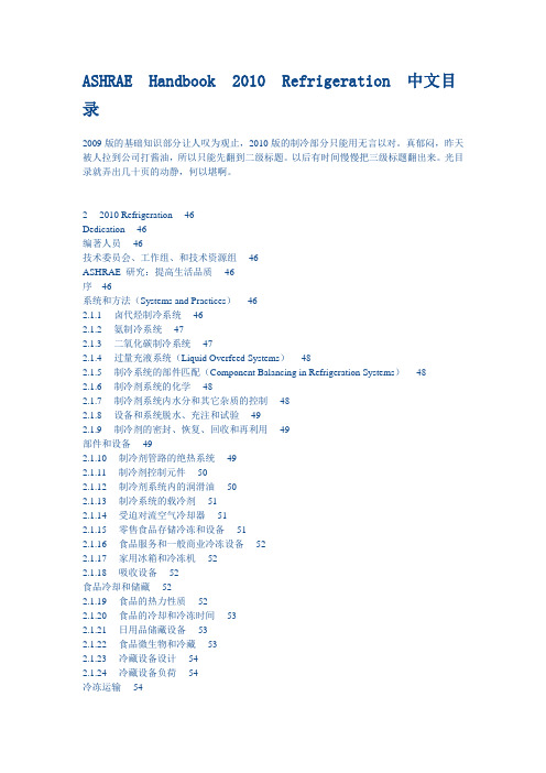
ASHRAE Handbook 2010 Refrigeration 中文目录2009版的基础知识部分让人叹为观止,2010版的制冷部分只能用无言以对。
真郁闷,昨天被人拉到公司打酱油,所以只能先翻到二级标题。
以后有时间慢慢把三级标题翻出来。
光目录就弄出几十页的动静,何以堪啊。
2 2010 Refrigeration 46Dedication 46编著人员 46技术委员会、工作组、和技术资源组 46ASHRAE 研究:提高生活品质 46序 46系统和方法(Systems and Practices) 462.1.1 卤代烃制冷系统 462.1.2 氨制冷系统 472.1.3 二氧化碳制冷系统 472.1.4 过量充液系统(Liquid Overfeed Systems) 482.1.5 制冷系统的部件匹配(Component Balancing in Refrigeration Systems) 482.1.6 制冷剂系统的化学 482.1.7 制冷剂系统内水分和其它杂质的控制 482.1.8 设备和系统脱水、充注和试验 492.1.9 制冷剂的密封、恢复、回收和再利用 49部件和设备 492.1.10 制冷剂管路的绝热系统 492.1.11 制冷剂控制元件 502.1.12 制冷剂系统内的润滑油 502.1.13 制冷系统的载冷剂 512.1.14 受迫对流空气冷却器 512.1.15 零售食品存储冷冻和设备 512.1.16 食品服务和一般商业冷冻设备 522.1.17 家用冰箱和冷冻机 522.1.18 吸收设备 52食品冷却和储藏 522.1.19 食品的热力性质 522.1.20 食品的冷却和冷冻时间 532.1.21 日用品储藏设备 532.1.22 食品微生物和冷藏 532.1.23 冷藏设备设计 542.1.24 冷藏设备负荷 54冷冻运输 542.1.25 货运集装箱、轨道运输、拖车和卡车 542.1.26 海运冷冻 552.1.27 航空运输 55食品、饮料和花卉应用 552.1.28 水果、蔬菜和鲜花的预冷 552.1.29 工业食品冷冻系统 562.1.30 肉类产品 562.1.31 禽类产品 562.1.32 鱼类产品 572.1.33 乳类产品 572.1.34 蛋和蛋类产品 572.1.35 阔叶树和藤类水果 582.1.36 柑橘类水果、香蕉和亚热带水果 582.1.37 蔬菜 592.1.38 果汁浓缩物和冷藏果汁产品 592.1.39 饮料 592.1.40 已处理食品,预加工过的食品和精制食品 60 2.1.41 烘焙食品 602.1.42 巧克力、糖果、坚果、干果和干燥蔬菜 61 工业应用 612.1.43 制冰 612.1.44 溜冰场 612.1.45 混凝土坝和次表土 622.1.46 化工中的制冷 622.1.47 低温应用 622.1.48 超低温制冷 632.1.49 生物医学应用和低温制冷 632.1.50 制冷术语 632.1.51 规范和标准 63ASHRAE Handbook 2009 Fundamental 中文目录花了三天的业余时间才把《ASHRAE Handbook 2009 Fundamental》目录翻译成中文,因为涉及的学科太多,很多专业名称采用的是直译,后续如果在阅读过程中有新发现我会修改过来。
- 1、下载文档前请自行甄别文档内容的完整性,平台不提供额外的编辑、内容补充、找答案等附加服务。
- 2、"仅部分预览"的文档,不可在线预览部分如存在完整性等问题,可反馈申请退款(可完整预览的文档不适用该条件!)。
- 3、如文档侵犯您的权益,请联系客服反馈,我们会尽快为您处理(人工客服工作时间:9:00-18:30)。
在任何清料过程中,必须穿戴合适的个人防护用具
• • • •
料筒清料 使用清料混合物可缩短清洁时间 如果清料混合物不适合,则使用天然(无色)原料 如果以上均不适合,则使用新颜色的原料
优化换色流程 • 将注塑速度增加至系统允许的最大值 • 将保压时间和冷却时间缩短至最低水平 • 将料筒温度降低20°C(68°F)至30°C(86°F) • 将分流板和主喷嘴温度升高20°C(68°F)至30°C(86°F) • 将注嘴温度升高20°C(68°F)至30°C(86°F)
84 螺栓固定式分流板系统 84 概述 86 安装参考
89 服务 89 模流分析 90 翻新 92 Altanium®温控器基本信息 92 温控器概述 94 主要优势 99 FTO(快速交货) 100 尺寸 101 操作界面 101 数字输入/输出选件 102 Delta3和Matrix2硬件概述 103 高级功能
9
浇口开孔尺寸
尺寸
注嘴 类型
A
浇口开孔尺寸(mm [in])
B
C
D
E
Ultra 250
HT-D HT-U HT-T
12.5
7.0
[0.49"] [0.2756"]
7.6 [0.30"]
3.4 [0.13"]
—
Ultra HT-DX 12.5
7.0
250 HT-TX [0.49"] [0.2756"]
热流道产品指南5.0版
7
产品矩阵
Ultra 250 Ultra 350 Ultra 500 Ultra 750 Ultra 1000
浇口类型
产品尺寸范围:
多孔型
HT 偏孔型
直通型
通用热浇口。适合大部分原 料。根据具体应用,可提供三 种不同的嘴头型号(浇口开孔 尺寸相同)
P P P P P*
多孔型
HT-X (延长型)
23 阀针式浇口的注嘴组件 23 主要优势 24 浇口质量准则 25 阀针驱动选件 26 产品矩阵 28 浇口开孔图 31 间距 33 Ultra 350热注嘴——应用指南 34 Ultra 500热注嘴——应用指南 35 Ultra 750热注嘴——应用指南 36 Ultra 1000热注嘴——应用指南 37 单喷嘴——单模腔阀针式浇口 38 Ultra Helix阀针式浇口 43 阀针式浇口气路设定与建议
导柱
电气接头
背板 分流板
供气管路 活塞 气缸 支承垫 定位环 主喷嘴加热器 主喷嘴衬套 模板冷却 支承隔热垫 分流板加热器 模板紧固螺栓
板定位销
热流道基本信息
2
热流道产品指南5.0版
热流道基本信息
喷嘴尺寸
L尺寸
BL尺寸
注嘴尺寸 Ultra 1000
L尺寸范围 热点式 阀针式浇口
BL尺寸范围 热点式 阀针式浇口
使用新颜色原料制造产品 • 完成换色后,将料筒和热流道系统的温度恢复至标准加工温度 • 如果此前使用了清料混合物或天然(无色)原料,则向送料系统添加新颜色 原料 • 根据标准参数调整注塑速度 • 开始用新颜色原料制造产品 • 开始生产新颜色产品
热流道产品指南5.0版
5
主要优势
UltraSeal®
热流道基本信息
Ultra优点
UltraGuide®
• 减少浇口和阀针磨损 • 在浇口之前预先导正阀针 • 直针柱面封胶
耐磨注嘴
• 加工磨损性材料时延长使 用寿命
UltraSeal®
• 防漏保证 • 更少的模板变形 • 喷嘴预载注嘴
宽广的温度操作范围
• 成型温度窗口宽,避免拉丝 和冻胶
28- 300mm 29.3-300mm 82-320mm 82-320mm [1.10-11.81"] [1.15-11.81"] [3.22-12.59"] [3.22-12.59"]
Ultra 750和Ultra Helix 750 (仅限于VG)
27.4-290mm 27.4-290mm 57-305mm 64-305mm [1.08-11.41"] [1.08-11.41"] [2.24-12"] [2.51-12"]
快速换色嘴头。提高换色 效果。常用语PP,PE材料
X X XPX
UP (Ultra包装)
包装用热浇口。 适用于高压、短周期的 包装应用。
X X XPX
UP-X (Ultra包装用延长型)
包装用延长型热浇口, 改进了浇口进出。 适用于高压、短周期的 包装应用。
X X XPX
P
标准产品
X 不提供
热流道产品指南5.0版
17-170mm 17–170mm 53-185mm 53-185mm [0.6-6.69"] [0.6-6.69"] [2.08-7.28"] [2.08-7.28"]
Ultra 250
13-150mm [0.51-5.90"]
不适用
79-165mm [2.75-6.49"]
不适用
热流道产品指南5.0版
HT-DX
23.8 [0.94"]
10.012 [0.394"]
44 叠模热流道 44 概述 45 热点式浇口考虑事项 46 阀针式浇口考虑事项 47 分体式浇道杆
目录
页面
50 PRONTO®标准配置热流道 50 概述 51 专为PRONTO®而设计 58 常见问题解答
60 Ultra SideGate侧浇口热流道 60 概述 64 Ultra SideGate——应用指南 65 Ultra SideGate斜角式 65 Ultra SideGate直列式 66 专用装置
• 注塑周期更短
• 可靠的密封
易于维护
• 注嘴、热电偶和加热器均可在 受压状态下进行更换
• 在冷却背板上使用单个O形 圈,减少维护需求
热流道产品指南5.0版
1
热流道系统
线夹 分流板感温线
分流板 衬套 阀针
UltraSeal® 分流板
中心定位隔热垫片
喷嘴主体 喷嘴加热器 喷嘴定位圈
喷嘴头 模板连接螺孔
SG斜角式 (Ultra SideGate)
侧浇口(斜角式)。 小型部件,浇口位于外部 一侧,通常较小、较长及 为圆柱形
X X XPX
SG直列式 (Ultra SideGate)
侧浇口(直列式)。 小型部件,浇口位于外部 一侧,通常较小、较长及 为圆柱形
X X XPX
HT-UF (UltraFlow®)
HT-S6
适合瓶盖应用的热浇口。 六孔注嘴,改进了瓶盖应用中 的换色
X X XPX
TS (大水口)
标准
延长型
大水口式浇口。 热转冷的应用。 成型产品上带一截冷流道。 浇口开孔简单。 延长型前段可用于产品仿型 加工。
X PPPP
P
标准产品
P*
并非所有特定类型的注嘴都有供应 请咨询赫斯基以了解更多信息
X 不提供
3.474 [0.137"]
Ultra 350
TS
16.0 [0.63"]
11.0 [0.43"]
9.5
5.71
[0.374"] [0.225"]
Ultra 500
HT-D HT-U HT-T
23.8 10.012 [0.94"] [0.394"]
7.0 [0.28"]
3.93 [0.155"]
Ultra 500
20.1 [.79"]
—
—
F
浇口开孔
A
B
—
C
D
AA BB
—
CE
Ultra 350
HT-D HT-U HT-T
16.0 [0.63"]
8.00 [0.31"]
8.3 [0.33"]
3.474 [0.137"]
Ultra HT-DX 16.0 350 HT-UX [0.63"]
8.00 [0.31"]
21.8 [.86"]
热注嘴组件
8
热流道产品指南5.0版
Ultra 250 Ultra 350 Ultra 500 Ultra 750 Ultra 1000
热注嘴组件
产品矩阵(续)
浇口类型
SG (Ultra SideGate)
产品尺寸范围:
侧浇口。 小型部件,浇口位于外部 一侧,通常较小、较长及 为圆柱形
X X XPX
3
熔融指数/粘度
原料
ABS CAP HDPE LDPE
PC PEI PETG PMMA PPA PPO PS PSU PUR TPE
PVC
SAN TPO
低粘度 23
LCP PA PBT PET POM PP 53 PPS
PBT/PC PC/ABS
中粘度 * 68
2
40 * *
* 2
高粘度
14
1
1
25
Ultra 500和Ultra Helix 500 (仅限于VG)
14-290mm 20-290mm 70-305mm 85-305mm [0.55-11.41"] [0.78-11.41"] [2.75-12"] [3.34-12"]
Ultra 350和Ultra Helix 350 (仅限于VG)
热流道 产品指南
第5版
目录
页面
1 热流道基本信息 1 Ultra的优势 2 热流道系统 3 注嘴尺寸 4 熔融指数/粘度 5 换色步骤