SMC气体压力传感器
SMC PSE53# 54# 550 56# 57# 系列压力传感器操作手册说明书

Pressure SensorOperation ManualPSE53#/54#/550/56#/57# SeriesThank you for purchasing an SMC PSE53#/54#/550/56#/57# Series Pressure Sensor.Please read this manual carefully before operating the product and make sure you understand its capabilities and limitations.Please keep this manual handy for future reference.To obtain the operation manual about this product, please refer to the SMC website (URL https://) or contact SMC directly.These safety instructions are intended to prevent hazardous situations and/or equipment damage.These instructions indicate the level of potential hazard with the labels of"Caution", "Warning" or "Danger". They are all important notes for safety and must be followed in addition to International standards (ISO/IEC) and other safety regulations.WiringOperatorSafety InstructionsNOTE•The direct current power supply to be used should be UL approved as follows:Circuit (of Class 2) which is of maximum 30 Vrms (42.4 V peak), with UL1310Class 2 power supply unit or UL1585 Class 2 transformer.•The product is a UL approved product only if it has a mark on the body.•Do not drop, hit or apply shock to the Pressure Sensor.•Do not pull the lead wire forcefully, or lift the product by pulling the lead wire.•Do not use in a place where the product could be splashed by oil or chemicals.•Wire correctly.•Do not perform wiring while the power is on.•Do not route wires and cables together with power or high voltage cables.•Be sure to ground terminal FG when using a commercially available switch-mode power supply.•When analogue output is used, install a noise filter (line noise filter, ferrite element, etc.) between the switch-mode power supply and this product.Specifications/Outline with DimensionsRefer to the product catalogue or SMC website (URL https://)for more information about the product specifications and outline dimensions.Note: Specifications are subject to change without prior notice and any obligation on the part of the manufacturer.© 2011-2022 SMC Corporation All Rights Reserved Akihabara UDX 15F, 4-14-1, Sotokanda, Chiyoda-ku, Tokyo 101-0021, JAPAN Phone: +81 3-5207-8249 Fax: +81 3-5298-5362URL https://Attaching the connector to the sensor wire•Strip the sensor wire as shown below.•Do not cut the insulation.•Check that the above preparation has been performed correctly, then part A shown should be pressed in by hand to make temporary connection.•Part A should then be pressed in using a suitable tool, such as pliers.•The e-con connector cannot be re-used once it has been fully crimped.In cases of connection failure such as incorrect order of wires or incomplete insertion, please use a new connector.•When connecting the sensor to the PSE200 or PSE300 series, use connector as listed below.•For information aboutconnectors please consult the manufacturerscatalogue.Controller and applicable sensorsConnecting/Disconnecting•When mounting the connector, insert it straight into the socket, holding thelever and connector body, and push the connector until the lever hooks into the housing, and locks.•When removing the connector, press down the lever to release the hook from the housing and pull the connector straight out.•PSE200A series (PSE5##)•PSE300series (PSE5##)PSE310series (PSE5##-28)•Insert the corresponding wire colour shown in the table into the pin number printed on the sensor connector, to the bottom.•Output specification•PSE5##Voltage output: 1 to 5 VOutput impedance: Approx. 1 kΩ•PSE57#-28Current output: 4 to 20 mAAllowable load impedance: 500 Ω or less (at 24 VDC)100 Ω or less (at 12 VDC)•PSE5#-28Current output: 4 to 20 mAAllowable load impedance: 500 Ω or less (at 24 VDC)100 Ω or less (at 12 VDC)∗: Install the load either on the LINE(+) or LINE(-) side.∗: The PSE53# and PSE54#series are not available with current output.Connecting the sensor cable•Insert the connector into the sensor, paying attention to the connector direction.•The sensor cable includes a connector cover to prevent the connector from falling out.•Install the connector cover to the sensor, rotating clockwise to lock.•To remove the sensor cable, rotate the connector cover anti-clockwise to release the lock, and remove connector cover. After removing the cover, pull out the connector.Piping connections•Cut the tube end perpendicular.•Insert the tubing to the sensor firmly for 8 mm or more from the end of the moulded pipe. The force necessary for piping insertion is approximately 25 N.•Insert the air tube for low pressure to Lo piping and the air tube for high pressure to Hi piping.Air tube (Applicable to I.D. 4)PSE53# seriesPSE550 series PSE54# seriesPSE56# seriesInternal circuit and wiring•When piping, apply a spanner to the piping section of the sensor.•Do not apply unnecessary forces such as twisting, pulling, moment loads, etc.on fittings or tubing.•When a tubing from a company other than SMC is used, ensure that the tubing has an internal diameter and tolerance of ø4±0.3 mm.•Applicable fluid is a fluid that does not corrode SUS316L.•When piping, apply a spanner to the piping section of the sensor.•To protect the sensor from water and dust, install an air tube to a safe area.PS ※※-OMO0006-C•Applicable fluid is a fluid that does not corrode C3604 + nickel plated,AI203 (aluminum oxide) and FKM.•When piping, apply a spanner to the piping section of the sensor.PSE57# series56∗: The pin numbers in the diagram indicate the PSE57#series 4 pin connector.All other series have 3 wires.∗: The pin numbers in the diagram indicate the PSE57#series 4 pin connector.。
气体压力传感器工作原理
气体压力传感器工作原理
气体压力传感器的工作原理是利用压力对一定区域内气体的作用力,通过感受元件将这个力转化为电信号进行检测和测量。
一种常见的气体压力传感器工作原理是利用压阻效应。
传感器内部包含一个柔性薄膜或薄片,它被感受到的压力作用在上面。
薄膜或薄片上覆盖有薄层电阻,当膜受到压力变形时,导电层的电阻值发生相应的改变。
这种改变可以通过电路进行检测,得到与压力相关的电信号输出。
另一种常见的工作原理是利用压电效应。
传感器内部包含一个压电材料,当受到外部压力时,压电材料会产生电荷。
通过将压电材料连接到电路中,可以测量和检测产生的电荷信号,从而得到压力的信息。
还有一种工作原理是利用气体压力作用在弹性体上造成弹性变形,传感器测量这种变形并将其转化为电信号。
这种传感器中的弹性体通常是由金属或弹性聚合物制成。
无论使用哪种工作原理,气体压力传感器的基本原理仍然是通过测量外部压力并将其转化为相应的电信号,以实现对气体压力的准确测量和监测。
SMC数显压力表

5.数值设置完毕后,按下S确认,会显示 H-1(迟滞值); 6.按下S确认,最后设置显示色; 7.全部设置完之后,长按S键3S返回主界 面(即可设置完成)。
例:设置值位为0.3pa,迟滞值为0.1mpa 0.3-0.1=0.2mpa;
当气压到达0.2mpa时会立即停止输出, 直到气压再次到达0.3mpa才会再次有输
恢复出厂设置:
图一
图二
图三
图四
1.在当前界面按住S键3秒:进入模式选取界面F0; 2.上下切换键切换到F99界面:按S键确认进入内部设定画面; 3.上下切换键切换OFF和ON选取,同时按下SET和下切换键5秒以 上确认恢复出厂设置; 4.按S键3秒返回当前界面。
单位选择:
MPA:兆帕 KPA : 千帕 Kgf/cm²:重量/每平方厘米 Bar:巴 Psi:磅/每平方英寸 InHg:英寸汞柱 mmHg;毫米汞柱
响应时间参数设置:
分辨率参数设置:
自动预功能设定:
微调值设定:F6-显示值微调:此
功能允许微调压力 开关的当前显示值, 调整范围为当前显 示值的+5%功能设定 模式下选择F6,按S 进入显示值微调。
省电模式:
密码设定:
设置方案:
项目 F0:单位功能选择 F1:0UT1规格设定 F2:0UT2规格设定 F3:响应时间设定 F4:分别率设定 F5:自动预设功能设定 F6:显示值校正 F7:省电模式选择 F8;密码锁设定
出信号。
比较值参数设置:
1.在F1中选择WIN(比较值模式); 2.按下S键会显示PIL(下限值)PIH(上限值); 3.1-P(常开),1-N(常闭)。
例:当在常开状态下,上限值PLH设置为0.4mpa, 下限值PIL设置为0.2mpa,迟滞值设为0.1mpa,那 么压力表的输出范围就在0.1mpa到0.5mpa之间
SMCISE20—N说明书
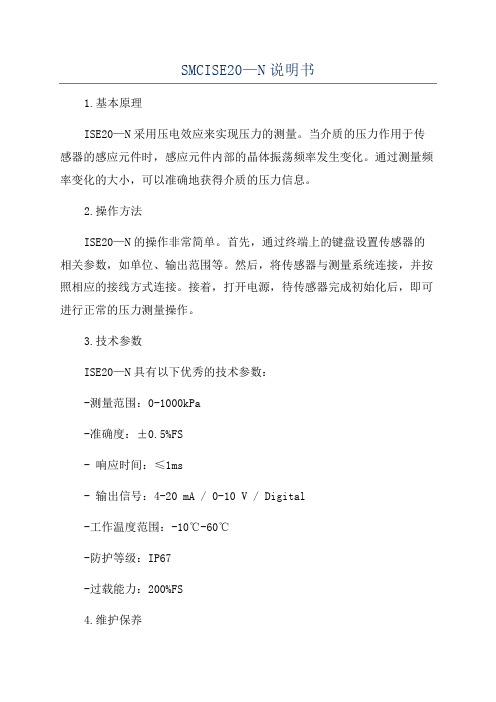
SMCISE20—N说明书1.基本原理ISE20—N采用压电效应来实现压力的测量。
当介质的压力作用于传感器的感应元件时,感应元件内部的晶体振荡频率发生变化。
通过测量频率变化的大小,可以准确地获得介质的压力信息。
2.操作方法ISE20—N的操作非常简单。
首先,通过终端上的键盘设置传感器的相关参数,如单位、输出范围等。
然后,将传感器与测量系统连接,并按照相应的接线方式连接。
接着,打开电源,待传感器完成初始化后,即可进行正常的压力测量操作。
3.技术参数ISE20—N具有以下优秀的技术参数:-测量范围:0-1000kPa-准确度:±0.5%FS- 响应时间:≤1ms- 输出信号:4-20 mA / 0-10 V / Digital-工作温度范围:-10℃-60℃-防护等级:IP67-过载能力:200%FS4.维护保养为确保ISE20—N的正常工作和延长使用寿命,需要进行定期的维护保养。
具体的维护保养事项包括:-定期清洁传感器的外壳,避免灰尘和污垢对传感器的影响;-检查传感器的接线是否松动,确保传感器与测量系统的正常连接;-定期校准传感器的测量精度,以确保其准确性和稳定性。
5.应用领域ISE20—N广泛应用于工业自动化和控制系统中的压力测量。
它适用于各种介质的压力监测和控制,如液体、气体、蒸汽等。
其高精度、高性能的特点,使得它在化工、食品加工、机械制造等行业中得到了广泛的应用。
总结:SMCISE20—N是一种高精度、高性能的数字压力传感器,具有广泛的应用领域和优越的性能特点。
本说明书详细介绍了ISE20—N的基本原理、操作方法、技术参数以及维护保养等方面的内容。
希望本说明书能够帮助用户更好地了解和使用ISE20—N,从而满足其在压力测量和控制领域的需求。
SMC压力传感器调整说明书 ZSE AISE A

5、错误显示与对策
错误
错误显示 报错原因
名称
处理对策
过电流
开关输出的负载电流超过 80mA
切断电源,检查输出部分电路, 确保电流在 80mA 以内后重新 开启电源
残压 异常
压力 异常
复制功 能异常
执行“清零”操作时供给压力 供给压力在指定范围内时再
不在±7%F.S(. 混合压型±3.5%) 执行“清零”操作 范围内.
功能设定模式下选择 F3,按
按
进入响应时间设定。
键
进入响应时间设定
响应时间设定: 按 和 选择响应时间值,按 确认
交替显示
响应时间
设定值
按 键确认
返回功能选择模式
F3-响应时间设定完成
5)、F4-显示精度设定:调整显示精度,用于消除末尾显示值跳动。
功能设定模式下选择 F4,按 进入显示精度设定。
按键
如果无 OUT2, 将输出检查部分 恢复为 A-常规输 出后, 按 键设定。
返回功能选择 模式
F98-输出检查完成
强制 ON
如果有 OUT2, 按 键设定, 设定方法同上。 设定完成后按住
键 2 秒钟以上, 返回测量模式。
测量模式
10
4)、F99-恢复出厂设置:用此功能将所有设置恢复为出厂设置。
在功能设定模式下选择 F99,按 进入恢复出厂设置。
主压力开关为要复制的压力、功能设置数据的来源,是被复制对象;
从压力开关为压力、功能设置数据要复制到的目的地。
从压力开关
主压力开关
1
2
N(N 最大为 10)
8
操作方法:在主压力开关的功能设定模式下选择 F97,按 进入复制功能设定。
(SMC压力传感器调整说明书)ZSE30AISE30A

Z/ISE30A 系列压力开关设定说明设定顺序:通电—测量模式—零点校正—功能设定—测量模式产品通电后,自动进入压力测量模式,第一次使用时,请按如下顺序操作。
1、零点校正:产品第一次使用时,通电且不施加气压时,如果显示值不为零,和键同时按住1s 以上,显示值归零。
2、基本功能设定:测量模式下按住键2s 以上,压力开关进入功能设定模式,显示屏显示为。
按和键选择对应功能后按进入详细功能设置。
备注:部分功能为可选功能,根据型号而定。
特定型号下如果不包含某可选功能,对应位置显示。
全部功能列表:项目出厂设置F0:单位选择功能 ISE-Mpa,ZSE-KPa,Option P-psi F1:OUT1规格设定 迟滞模式,常开F2:OUT2规格设定 迟滞模式,常开 F3:响应时间设定 2.5 ms F4:显示精度设定 1/1000 F5:自动预设功能设定 手动模式F6:显示值校正 0% F7:省电模式选择 OFF F8:密码锁设定OFF1)F0-单位选择功能可选功能,部分型号无此功能。
单位不同,显示屏开显示的数值范围不同。
操作方法:按和键选择对应单位,按键确认。
测量模式按住键2s 以上功 能 选 择 模 式功能设定2)F1-OUT1输出规格设定方法:此部分可设置输出类别(迟滞型/比较型)和输出模式(常开/常闭)设定。
按键进入单位选择模式按和键选择对应单位交替显示按键完成设定返回到功能选择模式,屏幕显示F0F0-单位选择功能设定完成输出模式常开型 出厂时默认设置常闭型迟滞模式(出厂时默认设置) 压力输出迟滞(H-1)压力输出压力输出迟滞(H-1)压力输出比较模式(也称窗口比较模式) 迟滞模式(出厂时默认设置) 比较模式(也称窗口比较模式) 迟滞(H1) 迟滞(H1)迟滞(H1) 迟滞(H1)功能选择模式下按和至屏幕显示,然后按进入OUT1规格设定。
压力设定状态:此状态下设定压力开关输出的ON/OFF 点。
以迟滞型为例:输出方法:当压力超过设定值时,开关输出变为ON 。
smc传感器的原理
smc传感器的原理
SMC传感器是一种基于压力测量的传感器,用于检测和测量
液体或气体系统中的压力变化。
它的工作原理基于压阻效应和压电效应。
首先,SMC传感器中使用了压阻效应。
传感器内部有一个薄膜,当外部施加压力时,薄膜会发生变形,导致膜阻值发生变化。
通过测量薄膜上电阻值的变化,可以确定外部压力的大小。
其次,SMC传感器还利用了压电效应。
在传感器的内部,有
一个压电晶体,当外部压力施加在晶体上时,晶体会产生电荷,这个电荷与外部压力成正比。
通过测量晶体上的电荷,可以得到外部压力的数值。
SMC传感器通常还配备了适当的电子电路,以将测量到的电
阻或电荷转换成可供使用的标准信号,如电流或电压。
这些信号可以被连接到其他设备或系统中进行进一步的处理和分析。
总的来说,SMC传感器基于压阻效应和压电效应,能够准确
测量和检测液体或气体系统中的压力变化。
这些传感器在工业、医疗、汽车和其他领域中广泛应用,为各种应用提供了可靠的压力监测和控制。
SMC压力传感器说明书
产品名称:SMC压力传感器说明书
SMCCORPORATION成立于1959年,总部设在日本东京都。
时至今日,SMC已成为世界级的气动元件研发、制造、销售商。
在日本本土更拥有庞大的市场网络,为客户提供产品及售后服务。
SMC 作为世界最著名的气动元件制造和销售的跨国公司,其销售网及生产基地遍布世界。
SMC产品以其品种齐全、可靠性高、经济耐用、能满足众多领域不同用户的需求而闻名于世。
在日本市场占有率已超过60%的SMC,通过分布于世界51个国家的海外子公司及分销商,将世界各国SMC产品的生产、销售连成一体,为用户提供直接、完善的服务。
SMC气动元件培训教程
SMC气动元件培训教程第一节:概述SMC是全球领先的气动元件制造商之一,其产品广泛应用于工业自动化领域。
本教程将介绍SMC气动元件的基本构造、工作原理和使用方法,帮助学习者快速上手使用和维护SMC气动元件。
第二节:基本构造1.气缸:气缸是SMC气动系统的核心元件,用于转换压缩空气的能量为机械运动。
其基本构造包括气缸体、活塞、密封装置等部分。
2.气源处理元件:气源处理元件用于净化和调节压缩空气质量和压力,包括滤油器、调压器、润滑器等。
这些元件可以帮助保护气动元件的寿命。
3.电磁阀:电磁阀用于控制气动元件的工作状态,包括开关电磁阀、速度控制电磁阀等。
通过电信号控制电磁阀的开关状态,可以实现气动元件的运动控制。
4.传感器:传感器用于检测气动元件的状态和位置,包括接近开关传感器、压力传感器、温度传感器等。
这些传感器可以帮助实现自动化的过程控制和状态监测。
第三节:工作原理1.气缸工作原理:当压缩空气通过气缸的进气口进入气缸体内时,气缸活塞会受到压力的作用向前移动或向后移动,从而实现线性运动。
气缸的运动方向和速度可以通过控制气缸两侧压力的大小和进气口的开关状态来实现。
2.电磁阀工作原理:电磁阀内部有电磁激励装置和阀门组成,当电磁激励装置接收到控制信号时,会产生磁场,使阀门打开或关闭。
从而控制气动元件的气源供给和排气。
第四节:使用方法1.安装:在使用SMC气动元件前,首先需要进行安装,根据实际需求选择合适的安装位置和方法。
对于气缸和电磁阀等元件,通常需要使用螺栓或支架进行固定。
对于气源处理元件,通常需要连接进气管路和排气管路。
2.连接:根据实际需求,使用适配器、接头等将气缸、电磁阀、气源处理元件等连接起来,确保气路畅通。
3.调试:在安装完成后,需要进行调试。
通过控制气源处理元件的调压器调节合适的气压,确保气缸的正常工作。
使用合适的电磁阀控制气缸的运行方向和速度。
4.维护:定期对SMC气动元件进行维护和保养,清洁气缸、更换密封件等。
气动距离传感器(密着)工作原理
SMC气动位置传感器ISA2作用和特性
*确认位置用的非接触式传感器。
*通过气桥回路和半导体式压力传感器的构成,不易受供给压力变动的影响。
*可稳定的检出0.01~0.5mm的间隙。
*带LED水平计,最适位置一目了然。
*集装时,增减位数简单。
采用插座式连接,减少配线工作。
*可与减压阀、2通电磁阀组合,减少配管工作。
SMC气动位置传感器ISA2动作原理
动作原理如下图所示,由气桥回路构成。
在检出喷口(S4)上提供检
测间隙,用设定手轮S3使加在压力传感器上的压力平衡(P1=P2)。
当检出喷口(S4)开放时,由压力传感器可检出产生的差压。
当工件
靠近检出喷口上,背压P2上升。
当P2≥P1时,开关输出ON,在检出间
隙以下,外部便有输出。
- 1、下载文档前请自行甄别文档内容的完整性,平台不提供额外的编辑、内容补充、找答案等附加服务。
- 2、"仅部分预览"的文档,不可在线预览部分如存在完整性等问题,可反馈申请退款(可完整预览的文档不适用该条件!)。
- 3、如文档侵犯您的权益,请联系客服反馈,我们会尽快为您处理(人工客服工作时间:9:00-18:30)。
产品名称:SMC气体压力传感器
传感器(英文名称:transducer/sensor)是一种检测装置,能感受到被测量的信息,并能将感受到的信息,按一定规律变换成为电信号或其他所需形式的信息输出,以满足信息的传输、处理、存储、显示、记录和控制等要求。
传感器的特点包括:微型化、数字化、智能化、多功能化、系统化、网络化。
它是实现自动检测和自动控制的首要环节。
传感器的存在和发展,让物体有了触觉、味觉和嗅觉等感官,让物体慢慢变得活了起来。
通常根据其基本感知功能分为热敏元件、光敏元件、气敏元件、力敏元件、磁敏元件、湿敏元件、声敏元件、放射线敏感元件、色敏元件和味敏元件等十大类。