工程电路分析答案(英文版)
工程电路分析英文版第八版课程设计

Engineering Circuit Analysis Eighth Edition Course Design IntroductionThe purpose of this course design is to guide students in understanding circuit analysis principles using the Engineering Circuit Analysis Eighth Edition textbook by William H. Hayt, Jack E. Kemmerly, and Steven M. Durbin.The course is assumed to be taught in an academic setting with students having a basic understanding of circuitanalysis concepts. The length of the course is 16 weeks with three hours of class per week and an additional hour for laboratory experiments.Learning OutcomesBy the end of this course, students should be able to: •Apply circuit analysis principles to analyze DC and AC circuits•Analyze the behavior of active circuits such as amplifiers and oscillators•Understand LTI (linear time-invariant) systems and their response to different input signals•Analyze circuits using Laplace transform and frequency domn techniques•Use MATLAB to solve circuit analysis problems and simulate circuitsCourse ContentWeek 1-2: Introduction and DC Circuit Analysis•Course introduction, syllabus review•Voltage, current, resistance, power, Ohm’s law•Kirchhoff’s laws, nodal and mesh analysis•Circuit theorems: superposition, Thevenin’s and Norton’s theorems•Applications: voltage and current dividers, Wheatstone bridgeWeek 3-4: Capacitors and Inductors•Capacitance, charge and energy stored in capacitors •Inductance, flux and energy stored in inductors•Series and parallel combinations of capacitors and inductors•Time domn analysis of RC and RL circuits•Transient analysis of first-order circuitsWeek 5-6: AC Circuit Analysis•AC circuits, phasors and complex numbers•Circuit analysis using phasors•Reactance, impedance and admittance•Applications: filters, resonance, transformers Week 7-8: LTI Systems and Frequency Domn Analysis •LTI systems: impulse response, step response, transfer function•Fourier series and Fourier transform•Frequency response: Bode plots, frequency domn analysis•Filters: low-pass, high-pass, band-pass, band-stop Week 9-10: Amplifiers•Basics of amplifiers, types of amplifiers•Amplifier characteristics: gn, input and output resistances, bandwidth•BJT amplifiers: biasing, small-signal models, analysis using hybrid-pi model•FET amplifiers: biasing, small-signal models, analysis using T-model•Applications: differential amplifiers, operational amplifiersWeek 11-12: Oscillators•Basics of oscillators, feedback concept•Conditions for oscillation, types of oscillators •Analysis of LC oscillator•Analysis of crystal oscillator•Frequency stability and feedback compensation Week 13-14: Laplace Transform•Introduction to Laplace transform•Laplace transform properties•Circuit analysis using Laplace transform•Inverse Laplace transform•Applications: circuit analysis of second-order circuits.Week 15-16: MATLAB•Introduction to MATLAB•Numeric computation using MATLAB•Symbolic computation using MATLAB•Circuit analysis using MATLAB•Laboratory experiments.AssessmentThe course will be assessed through a combination of homework assignments, quizzes, laboratory experiments, and a final examination. The weightage for each component is as follows:•Homework assignments: 20%•Quizzes: 20%•Laboratory experiments: 20%•Final examination: 40%ConclusionThis course design is intended to provide a comprehensive understanding of circuit analysis principles using the Engineering Circuit Analysis Eighth Edition textbook. It is expected to equip students with the skills to analyze and design circuits using both time domn and frequency domn techniques. The laboratory experiments and MATLAB assignments will help students to develop practical skills for circuit analysis.。
电路分析试题库(有答案)详解

第一章试题库一、填空题(建议较易填空每空0.5分,较难填空每空1分)1、电流所经过的路径叫做 电路 ,通常由 电源 、 负载 和 中间环节 三部分组成。
2、实际电路按功能可分为电力系统的电路和电子技术的电路两大类,其中电力系统的电路其主要功能是、对发电厂发出的电能进行 传输 、 分配 和 转换 ;电子技术的电路主要功能则是对电信号进行 传递 、 变换 、 存储 和 处理 。
3、实际电路元件的电特性 单一 而 确切 ,理想电路元件的电特性则 多元 和 复杂 。
无源二端理想电路元件包括 电阻 元件、 电感 元件和 电容 元件。
4、由 理想电路 元件构成的、与实际电路相对应的电路称为 电路模型 ,这类电路只适用 集总 参数元件构成的低、中频电路的分析。
5、大小和方向均不随时间变化的电压和电流称为 稳恒直流 电,大小和方向均随时间变化的电压和电流称为 交流 电,大小和方向均随时间按照正弦规律变化的电压和电流被称为 正弦交流 电。
6、 电压 是电路中产生电流的根本原因,数值上等于电路中 两点电位 的差值。
7、 电位 具有相对性,其大小正负相对于电路参考点而言。
8、衡量电源力作功本领的物理量称为 电动势 ,它只存在于 电源 内部,其参考方向规定由 电源正极高 电位指向 电源负极低 电位,与 电源端电压 的参考方向相反。
9、电流所做的功称为 电功 ,其单位有 焦耳 和 度 ;单位时间内电流所做的功称为 电功率 ,其单位有 瓦特 和 千瓦 。
10、通常我们把负载上的电压、电流方向称作 关联 方向;而把电源上的电压和电流方向称为 非关联 方向。
11、 欧姆 定律体现了线性电路元件上电压、电流的约束关系,与电路的连接方式无关; 基尔霍夫 定律则是反映了电路的整体规律,其中 KCL 定律体现了电路中任意结点上汇集的所有 支路电流 的约束关系, KVL 定律体现了电路中任意回路上所有 元件上电压 的约束关系,具有普遍性。
《电路分析基础》习题参考答案
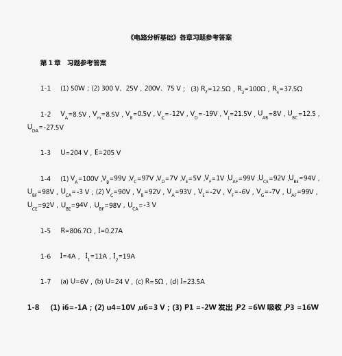
《电路分析基础》各章习题参考答案第1章习题参考答案1-1 (1) SOW; (2) 300 V、25V,200V、75V; (3) R=12.50, R3=1000, R4=37.5021-2 V =8.S V, V =8.S V, V =0.S V, V =-12V, V =-19V, V =21.S V U =8V, U =12.5,A mB D 'AB B CU =-27.S VDA1-3 Li=204 V, E=205 V1-4 (1) V A=lOO V ,V=99V ,V c=97V ,V0=7V ,V E=S V ,V F=l V ,U A F=99V ,U c E=92V ,U8E=94V,8U BF=98V, u cA=-3 V; (2) V c=90V, V B=92V, V A=93V, V E=-2V, V F=-6V, V G=-7V, U A F=99V, u c E=92V, U B E=94V, U BF=98V, U C A =-3 V1-5 R=806.70, 1=0.27A1-6 1=4A ,11 =llA ,l2=19A1-7 (a) U=6V, (b) U=24 V, (c) R=SO, (d) 1=23.SA1-8 (1) i6=-1A; (2) u4=10V ,u6=3 V; (3) Pl =-2W发出,P2=6W吸收,P3=16W吸收,P4=-lOW发出,PS=-7W发出,PG=-3W发出1-9 l=lA, U5=134V, R=7.801-10 S断开:UAB=-4.SV, UA0=-12V, UB0=-7.2V; S闭合:12 V, 12 V, 0 V1-12 UAB=llV / 12=0.SA / 13=4.SA / R3=2.401-13 R1 =19.88k0, R2=20 kO1-14 RPl=11.110, RP2=1000第2章习题参考答案2-1 2.40, SA2-2 (1) 4V ,2V ,1 V; (2) 40mA ,20mA ,lOmA 2-3 1.50 ,2A ,1/3A2-4 60 I 3602-5 2A, lA2-6 lA2-7 2A2-8 lOA2-9 l1=1.4A, l2=1.6A, l3=0.2A2-10 11=OA I l2=-3A I p l =OW I P2=-l8W2-11 11 =-lA, l2=-2A I E3=10V2-12 11=6A, l2=-3A I l3=3A2-13 11 =2A, l2=1A ,l3=1A ,14 =2A, l5=1A2-14 URL =30V I 11=2.SA I l2=-35A I I L =7.SA2-15 U ab=6V, 11=1.SA, 12=-lA, 13=0.SA2-16 11 =6A, l2=-3A I l3=3A2-17 1=4/SA, l2=-3/4A ,l3=2A ,14=31/20A ,l5=-11/4A12-18 1=0.SA I l2=-0.25A12-19 l=1A32-20 1=-lA52-21 (1) l=0A, U ab=O V; (2) l5=1A, U ab=llV。
《电路分析基础》第2版习题参考答案2014tjh
《电路分析基础》第2版-习题参考答案-2014-tjh《电路分析基础》各章习题参考答案第1章习题参考答案1-1 (1) 50W;(2) 300 V、25V,200V、75 V;(3) R2=12.5Ω,R3=100Ω,R4=37.5Ω1-2 V A=8.5V,V m=6.5V,V B=0.5V,V C=−12V,V D=−19V,V p=−21.5V,U AB=8V,U BC=12.5,U DA=−27.5V1-3 电源(产生功率):A、B元件;负载(吸收功率):C、D元件;电路满足功率平衡条件。
1-4 (1) V A=100V,V B=99V,V C=97V,V D=7V,V E=5V,V F=1V,U AF=99V,U CE=92V,U BE=94V,U BF=98V,U CA=−3 V;(2)V C=90V,V B=92V,V A=93V,V E=−2V,V F=−6V,V G=−7V,U AF=99V,U CE=92V,U BE=94V,U BF=98V,U CA=−3 V1-5 I≈0.18A ,6度,2.7元1-6 I=4A,I1=11A,I2=19A1-7 (a) U=6V,(b) U=24 V,(c) R=5Ω,(d) I=23.5A1-8 (1) i6=−1A;(2) u4=10V,u6=3 V;(3) P1 =−2W发出,P2 =6W吸收,P3 =16W吸收,P4 =−10W发出,P5 =−7W发出,P6 =−3W发出1-9 I=1A,U S=134V,R≈7.8Ω1-10 S断开:U AB=−4.8V,U AO=−12V,U BO=−7.2V;S闭合:U AB=−12V,U AO=−12V,U BO=0V1-11 支路3,节点2,网孔2,回路31-12 节点电流方程:(A)I1+I3−I6=0,(B)I6−I5−I7=0,(C)I5 +I4−I3=0回路电压方程:①I6 R6+ U S5 +I5 R5−U S3+I3 R3=0,②−I5 R5−U S5+ I7R7−U S4=0,③−I3 R3+ U S3 + U S4 + I1 R2+ I1 R1=01-13 U AB=11V,I2=0.5A,I3=4.5A,R3≈2.4Ω1-14 V A=60V,V C=140V,V D=90V,U AC=−80V,U AD=−30V,U CD=50V1-15I1=−2A,I2=3A,I3=−5A,I4=7A,I5=2A第2章习题参考答案2-1 2.4 Ω,5 A2-2 (1) 4 V,2 V,1 V;(2) 40 mA,20 mA,10 mA2-3 1.5 Ω,2 A,1/3 A2-4 6 Ω,36 Ω2-5 2 A,1 A2-6 1 A2-7 2 A2-8 1 A2-9 I1 = −1.4 A,I2 = 1.6 A,I3 = 0.2 A2-10 I1 = 0 A,I2 = −3 A,P1 = 0 W,P2 = −18 W 2-11 I1 = −1 mA,I2 = −2 mA,E3 = 10 V2-12 I1 = 6 A,I2 = −3 A,I3 = 3 A2-13 I1 =2 A,I2 = 1A,I3 = 1 A,I4 =2 A,I5 = 1 A2-14 V a = 12 V ,I1 = −1 A,I2 = 2 A2-15 V a = 6 V,I1 = 1.5 A,I2 = −1 A,I3 = 0.5 A 2-16 V a = 15 V,I1 = −1 A,I2 = 2 A,I3 = 3 A 2-17 I1 = −1 A,I2 = 2 A2-18 I1 = 1.5 A,I2 = −1 A,I3 = 0.5 A2-19 I1 = 0.8 A,I2 = −0.75 A,I3 = 2 A,I4 = −2.75 A,I5 = 1.55 A2-20 I3 = 0.5 A2-21 U0 = 2 V,R0 = 4 Ω,I0 = 0.1 A2-22 I5 = −1 A2-23 (1) I5 = 0 A,U ab = 0 V;(2) I5 = 1 A,U ab = 11 V2-24 I L = 2 A2-25 I S =11 A,R0 = 2 Ω2-26 18 Ω,−2 Ω,12 Ω2-27 U=5 V2-28 I =1 A2-29 U=5 V2-30 I =1 A2-31 10 V,180 Ω2-32 U0 = 9 V,R0 = 6 Ω,U=15 V第3章习题参考答案3-1 50Hz,314rad/s,0.02s,141V,100V,120°3-2 200V,141.4V3-3 u=14.1sin (314t−60°) V3-4 (1) ψu1−ψu2=120°;(2) ψ1=−90°,ψ2=−210°,ψu1−ψu2=120°(不变)3-5 (1) 150290VU=︒;U=∠︒,25020V(2) u3=1002sin (ωt+45°)V,u42 (ωt+135°)V3-6 (1) i1=14.1 sin (ωt+72°)A;(2) u2=300 sin (ωt-60°)V3-7 错误:(1) ,(3),(4),(5)3-8 (1) R;(2) L;(3) C;(4) R3-9 i=2.82 sin (10t−30°) A,Q≈40 var3-10 u=44.9sin (314t−135°) V,Q=3.18 var3-11 (1) I=20A;(2) P=4.4kW3-12 (1)I ≈1.4A , 1.430A I ≈∠-︒;(3)Q ≈308 var ,P =0W ;(4) i ≈0.98 sin (628t −30°) A3-13 (1)I =9.67A ,9.67150A I =∠︒,i =13.7 sin (314t +150°) A ;(3)Q =2127.4 var ,P =0W ;(4)I C =0A3-14 (1)C =20.3μF ;(2) I L =0.25A ,I C =16A第4章 习题参考答案4-1 (a) 536.87Z =∠︒Ω,0.236.87S Y =∠-︒;(b) 2.5245Z =∠-︒Ω,0.2245S Y =∠︒4-2 Y =(0.06-j0.08) S ,R ≈16.67 Ω,X L =12.5Ω,L ≈0.04 H4-3 R 600V U =∠︒,L 8090V U =∠︒,S 10053.13V U =∠︒4-4 2036.87A I =∠-︒4-5 100245Z =∠︒Ω,10A I =∠︒,R 1000V U =∠︒,L 12590V U =∠︒,C 2590V U =∠-︒4-6 0.25245S Y =∠︒,420V U =∠︒,R 20A I =∠︒,L 0.2290A I =∠-︒,C 1.2290A I =∠︒4-7 10245A I =∠︒,S10090V U =∠︒4-8 (a) 30 V ;(b) 2.24 A4-9 (a) 10 V ;(b) 10 A4-10 (a) 10 V ;(b) 10 V4-11 U =14.1 V4-12 U L1 =15 V ,U C2 =8 V ,U S =15.65 V 4-13 U X1 =100 V ,U 2 =600 V ,X 1=10 Ω,X 2=20Ω,X 3=30 Ω4-14 20245Z =∠︒Ω,245A I =∠-︒,120A I =∠︒,2290A I =∠-︒,ab 0V U = 4-15 (1)2A I =,RC 52Z =,510Z =;(2)10R =Ω,C 10X =Ω 4-16 P = 774.4 W ,Q = 580.8 var ,S = 968 V·A 4-17 I 1 = 5 A ,I 2 = 4 A4-18 I 1 = 1 A ,I 2 = 2 A ,526.565A I =∠︒,26.565V A 44.72S =∠-︒⋅4-19 10Z =Ω,190A I =∠︒,R252135V U =∠︒,10W P = 4-20 ω0 =5×10⁶ rad/s ,ρ = 1000 Ω,Q = 100,I = 2 mA ,U R =20 mV ,U L = U C = 2 V4-21 ω0 =104 rad/s ,ρ = 100 Ω,Q = 100,U =10 V ,I R = 1 mA ,I L = I C = 100 mA4-22 L 1 = 1 H ,L 2 ≈ 0.33 H第5章 习题参考答案5-3 M = 35.5 mH 5-4 ω01 =1000 rad/s ,ω02 =2236 rad/s 5-5 Z 1 = j31.4 Ω,Z 2 = j6.28 Ω 5-6 Z r = 3+7.5 Ω 5-7 M = 130 mH 5-8 2245A I =∠︒ 5-9 U 1 = 44.8 V 5-10 M 12 = 20 mH ,I 1 = 4 A 5-11 U 2 = 220 V ,I 1 = 4 A5-12 n = 1.9 5-13 N 2 = 254匝,N 3 = 72匝 5-14 n = 10,P 2 = 31.25 mW第6章 习题参考答案6-1 (1) A 相灯泡电压为零,B 、C 相各位为220V 6-3 I L = I p = 4.4 A ,U p = 220 V ,U L = 380 V ,P = 2.3 kW 6-4 (2) I p = 7.62 A ,I L = 13.2 A 6-5 A 、C 相各为2.2A ,B 相为3.8A 6-6 U L = 404 V 6-7 A N 20247U ''=∠-︒V 6-8 cos φ = 0.961,Q = 5.75 kvar 6-9 33.428.4Z =∠︒Ω 6-10 (1) I p = 11.26 A ,Z = 19.53∠42.3° Ω; (2) I p = I l = 11.26 A ,P = 5.5 kW 6-11 U l = 391 V6-12 A 222t 53.13)A i ω=-︒B 222t 173.13)A i ω=-︒C 222t 66.87)A i ω=+︒ 6-13 U V = 160 V 6-14 (1) 负载以三角形方式接入三相电源 (2) AB 3.8215A I =∠-︒,BC 3.82135A I =∠-︒,CA 3.82105A I =∠︒A 3.8645A I =∠-︒,B 3.86165A I =∠-︒,C 3.8675A I =∠︒ 6-15 L = 110 mH ,C = 91.9 mF第7章 习题参考答案7-1 P = 240 W ,Q = 360 var 7-2 P = 10.84 W7-3 (1)() 4.7sin(100)3sin3A i t t t ωω=+︒+(2) I ≈3.94 A ,U ≈58.84 V ,P ≈93.02 W7-4 m12π()sin(arctan )V 2MU L u t t z R ωωω=+-,221()z R L ω=+7-5 直流电源中有交流,交流电源中无直流7-6 U 1=54.3 V ,R = 1 Ω,L = 11.4 mH ;约为8%,(L ’ = 12.33 mH )7-7 使总阻抗或总导纳为实数(虚部为0)的条件为12X /R R R L C ===7-8 19.39μF C =,275.13μF C = 7-9 L 1 = 1 H ,L 2 = 66.7 mH 7-10 C 1 = 10 μF ,C 2 = 1.25 μF第8章 习题参考答案8-6 i L (0+)=1.5mA ,u L (0+)=−15V8-7 i 1(0+)=4A ,i 2(0+)=1A ,u L (0+)=2V ,i 1(∞)=3A ,i 2(∞)=0,u L (∞)=08-8 i 1(0+)=75mA ,i 2(0+)=75mA ,i 3(0+)=0,u L1(0+)=0,u L2(0+)=2.25V8-9 6110C ()2e A t i t -⨯=8-10 4L ()6e V t u t -=8-11 6110C ()10(1e )V t u t -⨯=-,6110C ()5e A t i t -⨯=*8-12 500C ()115e sin(86660)V t u t -=+︒8-13 10L ()12e V t u t -=,10L()2(1e )A ti t -=-8-14 21R S ()e V t R C u t U -=-,3R S (3)e V u U τ-=-8-15 (1) τ=0.1s ,(2) 10C ()10e V t u t -=,(3) t =0.1s 8-16 510C ()109e V t u t -=-8-17 10L ()5e A t i t -=8-18 (a)00()1()1(2)f t t t t t =---;(b)00000()1()1()[1()1(2)]1()21()1(2)f t t t t t t t t t t t t t =------=-⨯-+- 8-19 0.50.5(1)C()[5(1e )1()5(1e )1(-1)]V t t u t t t ---=--- 8-20 u o 为三角波,峰值为±0.05V*8-21 临界阻尼R L C ,欠阻尼R L C ,过阻尼R L C *8-22 12666L ()[(1e)1()(1e )1(1)2(1e )1(2)]t t t i t t t t -----=-+-----。
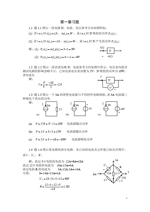
电路分析课后习题答案第一章
则可列两个方程:
联解方程可得:
1.14题1.14图示电路为计算机加法原理电路,已知 , , , , , ,求ab两端的开路电压 。
解:电源 回路的电流为:
电源 回路的电流为:
可得:
1.15题1.15图示电路,当
(1)开关S打开时,求电压 。
(2)开关S闭合时,求电流 。
解:(1)列回路电压方程,有:
解得:
(2)列电压方程,有:
消去 ,可得:
(3)流过2Ω电阻的电流为:
而从回路可知: 可得:
则得:
1.23 (1)题1.23图(a)电路,已知 , , ,求电流 。
(2)题1.23图(b)电路,已知电阻上消耗功率 ,求电阻 。
解:(a)从a点对受控源部分进行电压源等效如图所示:
(c)开路电压为: 等效电阻为:
短路电流为: 等效电阻为:
(d)开路电压为: 等效电阻为:
短路电流为: 等效电阻为:
1.19 (1)若题1.19图(a)中电流I=0,求电阻R。
(2)若题1.19图(b)中 ,求电源 。
解:(1)由于I=0,则有:
解得:
(2)由回路电流,可列方程为:
将 代入,解得:
1.20题1.20图示电路,求电流 。
(c)开路时,8Ω电阻的电压为
2Ω电阻的电压为
可得:
1.7求题1.7图示各电路的电流I。
解:(a)
(b)
(c)将电压源等效为电流源,如右图示
显然
(d)电压源供出的总电流为:
根据分流关系,流过3Ω电阻的电流为
流过12Ω电阻的电流为
可得:
1.8求题1.8图示各电路的电压U。
工程电路分析英文版第八版教学设计
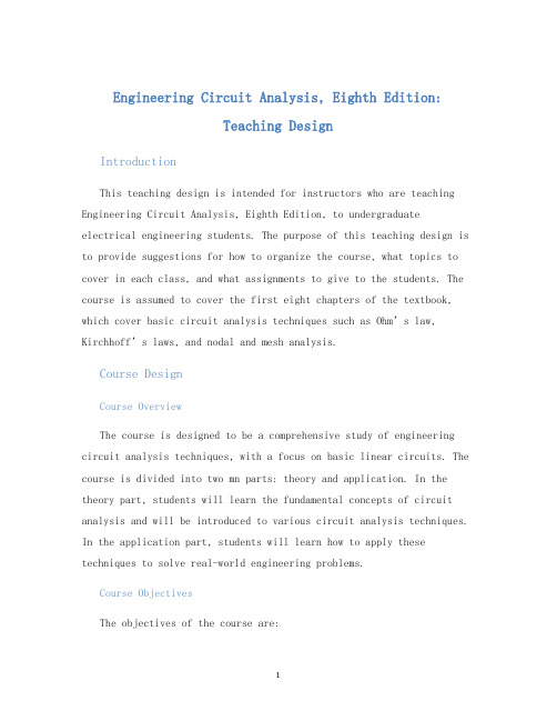
Engineering Circuit Analysis, Eighth Edition:Teaching DesignIntroductionThis teaching design is intended for instructors who are teaching Engineering Circuit Analysis, Eighth Edition, to undergraduateelectrical engineering students. The purpose of this teaching design is to provide suggestions for how to organize the course, what topics to cover in each class, and what assignments to give to the students. The course is assumed to cover the first eight chapters of the textbook, which cover basic circ uit analysis techniques such as Ohm’s law, Kirchhoff’s laws, and nodal and mesh analysis.Course DesignCourse OverviewThe course is designed to be a comprehensive study of engineering circuit analysis techniques, with a focus on basic linear circuits. The course is divided into two mn parts: theory and application. In the theory part, students will learn the fundamental concepts of circuit analysis and will be introduced to various circuit analysis techniques. In the application part, students will learn how to apply these techniques to solve real-world engineering problems.Course ObjectivesThe objectives of the course are:•To teach students the fundamental concepts of circuit analysis.•To teach students various circuit analysis techniques.•To teach students how to apply these techniques to solve real-world engineering problems.•To teach students how to design basic circuits.•To prepare students for further study in electrical engineering.Course ScheduleThe course is designed to cover the first eight chapters of the textbook in a 16-week semester. The following is a tentative schedule of what topics will be covered in each class:Week 1•Introduction to circuit analysis•History of circuit analysis•Units and standards•Voltage and currentWeek 2•Power and energy•Kirchhoff’s laws•Series-parallel circuitsWeek 3•Voltage and current division•Source transformation•Node-voltage analysisWeek 4•Mesh-current analysis•Superposition•Thevenin’s and Norton’s theoremsWeek 5•Maximum power transfer•Delta-to-wye and wye-to-delta transformations•Capacitors and inductorsWeek 6•First-order circuits•Second-order circuits•Sinusoidal sourcesWeek 7•Phasors•Impedance and admittance•Series and parallel resonanceWeek 8•Two-port networks•Transmission parameters•Hybrid parametersWeek 9-16•Applications of circuit analysis to electronic circuits•Design and analysis of amplifiers•Design and analysis of filters•Design and analysis of oscillators•Design and analysis of power supplies•Design and analysis of digital circuitsCourse MaterialsThe mn textbook for the course is Engineering Circuit Analysis,Eighth Edition by William H. Hayt Jr. and Jack E. Kemmerly. In addition, students will need access to a calculator, graph paper, and a computer with a circuit analysis software package such as SPICE.AssignmentsThe following types of assignments are suggested for this course: •Weekly problem sets, consisting of 10-12 problems based on the material covered in the previous week’s lectures.•Midterm exams, consisting of a mixture of short-answer questions and problem-solving questions. The exam questions should cover all the material covered up to that point in the course.•Final exam, covering all the material covered in the course.•Design project, where students design and build a basic electronic circuit and report on its performance.•Homework assignments, consisting of readings and online exercises to help students review the material covered in class.AssessmentThe final grade for the course should be based on a combination of the student’s performance on assignments and exams. The following grading scheme is suggested:•Weekly problem sets: 30%•Midterm exams: 30%•Final exam: 40%ConclusionThis teaching design is meant to be flexible and can be adapted to fit the needs of each instructor. However, it is suggested that the instructor use this as a starting point for organizing their course and assignments. By following this teaching design, students should be well-prepared for further study in electrical engineering and should have a good understanding of basic circuit analysis techniques.。
电路分析基础(英文版)课后答案第三章
0 = ¡26i1 ¡ 90i2 + 124i3
[a] Solving, i1 = 5 A; therefore the 80 V source is delivering 400 W to the circuit.
[b] Solving, i3 = 2:5 A; therefore p8− = (6:25)(8) = 50 W
v1 + v1 ¡ v2 = 4:5
1
8
53
54 CHAPTER 3. Techniques of Circuit Analysis
v2 + v2 ¡ v1 + v2 ¡ 30 = 0
12 8
4
Solving, v1 = 6 V v2 = 18 V Thus, i = (v1 ¡ v2)=8 = ¡1:5 A v = v2 + 2i = 15 V
DE 3.8 Use the lower node as the reference node. Let v1 = node voltage across the 7.5 − resistor and v2 = node voltage across the 2.5 − resistor. Place the dependent voltage source inside a supernode between the node voltages v and v2. The node voltage equations are
3
Techniques of Circuit Analysis
Drill Exercises
DE 3.1 [a] 11,8 resistors, 2 independent sources, 1 dependent source
电路分析习题及答案
电路分析习题及答案(总8页)--本页仅作为文档封面,使用时请直接删除即可----内页可以根据需求调整合适字体及大小--21、用网孔分析法求图1电路的网孔电流,图中r=1Ω。
2、图2所示电路中的运放工作于线性区,试用叠加定理求输出电压U O 。
4V+_+_Ω0.2mA图1 图23、电路如图3所示。
已知U=,I=,求该单口网络的戴维宁等效电路。
+20V+20V(a ) (b)图34、如图4所示二端网络N 中只含有一个电阻和一个电感,其端钮电压u 及电流i 的波形如图中所示。
(1)试确定R 和L 是如何联接的 (2)求R 、L 值。
5、电路如图5所示,开关断开已经很久, t=0时开关转换,试求0 t 的电流)(t i 。
3+_图5 图66、图6所示电路,已知电压表的读数为V 1=3V ,V 2=4V 。
求电压表V 3的读数并做出相量图。
7、图7(a )所示电路中电流1i 和2i 的波形如图7(b )所示。
试绘出1u 和2u 的波形。
11(a )(b )图78、图8是电感线圈和电容器并联的电路模型。
已知R=1Ω,L=,C=μF,求电路的谐振角频率和谐振时的阻抗。
11'22'C图8 图99、图9所示N 为纯电阻对称电路(电阻参数R 11=R 22,R 12=R 21)。
当2-2’端开路时,1-1’端的输入电阻R 1=9Ω。
当1-1’端接入电压源U S 时,2-2’端接入负载R L 时,U 22’=4V ,且此时R L 获得最大功率为2W 。
求当U S =11V ,R L =3Ω时电压源输出的功率。
41、用结点分析法求图1电路的结点电压,图中r=1Ω。
2、求图2所示单口网络的戴维宁等效电路和电阻R L 可获得的最大功率。
r=2Ω2ΩI4L图1 图23、图3所示电路中的运放工作于线性区,试用叠加定理求输出电压U O 。
4、电路如图4所示,开关断开已经很久,t=0时开关转换,试求0≥t 时的电容电压)(t u C0.2mAΩ图3 图45、图5所示电路,已知电流表的读数为A 1=1A ,A 2=2A 。
工程电路分析第八版第二章答案
Engineering Circuit Analysis
8th Edition
Chapter Two Exercise Solutions
16.
q = i.t = (10-9 A)(60 s) = 60 nC
Copyright ©2012 The McGraw-Hill Companies. Permission required for reproduction or display. All rights reserved.
Chapter Two Exercise Solutions
7.
(a) P = 550 mJ/ 15 ns = 36.67 MW (b) Pavg = (550 mJ/pulse)(100 pulses/s) = 55 J/s = 55 W
Copyright ©2012 The McGraw-Hill Companies. Permission required for reproduction or display. All rights reserved.
Copyright ©2012 The McGraw-Hill Companies. Permission required for reproduction or display. All rights reserved.
Engineering Circuit Analysis
8th Edition
Engineering Circuit Analysis
8th Edition
Chapter Two Exercise Solutions
17.
(a) # electrons = -1013 C/(-1.602×10-19 C/electron) = 6.242×1031 electrons
电路分析期末考试答案
电路分析期末考试答案一.选择题1.两个电阻,当它们串联时,功率比为4:9;若它们并联,则它们的功率比为:(B)。
(A)4:9(B)9:4(C)2:3(D)3:22.如图1所示电路,I1=D。
(A)0.5A(B)-1A(C)(D)2A3.由电压源、电流源的特性知,几个(B)的电压源可以等效为一个电压源;几个(A)的电流源可以等效为一个电流源,电压源与任意二端元件(A),可以等效为电压源;电流源与任意二端元件(B),可以等效为电流源.A、并联B、串联C、混合联接D、无法连接4.用戴维南定理分析电路求端口等效电阻时,电阻为该网络中所有独立电源置零时的等效电阻。
其独立电源置零是指(C)。
A、独立电压源开路,独立电流源短路B、独立电压源短路,独立电流源短路C、独立电压源短路,独立电流源开路D、以上答案都不对5.在稳定的直流电路中,动态元件电容的(C)。
A、电压不一定为零B、电压一定为零C、电流一定为零D、电流不停变动6.正弦电路中,感抗与角频率成(A),容抗与角频率成()。
A、正比反比B、正比正比C、反比反比D、反比正比7.三相对称电路中,三相对称负载Y形连接,则电路的线电压与相电压的关系为(C)A、线电压与相电压相等;B、线电压是相电压的3倍,并超前30度;C、线电压是相电压的3倍,并滞后30度;D、线电压与相电压数值相等,并且线电压超前相电压30度。
8.三相四线制电路,已知∠=•3020AI A,-∠=•9020B I A,∠=•15020C I A,则中线电流N•I为(D)A、10AB、20AC、30AD、0A11.处于谐振状态的RLC串联电路,当电源频率升高时,电路将呈现出(B)A、电阻性B、电感性C、电容性9.符合无损耗、K=1和自感量、互感量均为无穷大,但两者比值是限值条件的变压器是(A)A、理想变压器B、全耦合变压器C、空芯变压器10.在换路瞬间,下列说法中正确的是(A)A、电感电流不能跃变B、电感电压必然跃变C、电容电流必然跃变11、已知接成Y形的三个电阻都是60Ω,则等效Δ形的三个电阻阻值为(D)A、全是20ΩB、两个20Ω一个180ΩC、两个180Ω一个200ΩD、全是180Ω12、已知空间有a、b两点,电压U ab=8V,a点电位为V a=3V,则b点电位V b为(B)A、5VB、-5VC、11VD、15V13、电感元件的正弦交流电路中,电压有效值不变,当频率增大时,电路中电流将(B)A、增大B、减小C、不变D、不确定14、314μF电容元件用在100Hz的正弦交流电路中,所呈现的容抗值为(C)A、ΩB、ΩC、ΩD、51Ω15、已知电路复阻抗Z=(3+j4)Ω,则该电路一定呈(A)A、感性B、容性C、阻性D、不确定16、下列说法中,(A)是正确的。
- 1、下载文档前请自行甄别文档内容的完整性,平台不提供额外的编辑、内容补充、找答案等附加服务。
- 2、"仅部分预览"的文档,不可在线预览部分如存在完整性等问题,可反馈申请退款(可完整预览的文档不适用该条件!)。
- 3、如文档侵犯您的权益,请联系客服反馈,我们会尽快为您处理(人工客服工作时间:9:00-18:30)。
2010-9-25
福建师范大学电子信息工程系
21
PROBLEM 4 .25
PROBLEM 4 .26
PROBLEM 4 .27
PROBLEM 4 .28
2010-9-25
福建师范大学电子信息工程系
22
PROBLEM 4 .29
PROBLEM 4 .30
PROBLEM 4 .31
PROBLEM 4 .32
2010-9-25 福建师范大学电子信息工程系 1
solution : v1 v1 vP fornode:10= + 1 →3v1 vP = 400 20 40 vP vP v1 vP v3 fornode : 0 = + 2 + →5v1 +11 P 4v3 = 0 v 100 40 50 vP v3 v3 v4 fornode : 3 + 2 = 2.5+ + →vP 6v3 +5v4 = 25 50 10 v3 v4 v4 fornode : 4 +5 = + 2 →20 3 + 21 4 = 600 v v 10 200
i4 = i3 2 = 5.17 p = 2.2 * (2.84 4.5) = 3.652(W )
2010-9-25
福建师范大学电子信息工程系
25
PROBLEM 4 .34
PROBLEM 4 .35
PROBLEM 4 .36
2010-9-25
福建师范大学电子信息工程系
26
PROBLEM 4 .37/38
Chapter 4
4 .7
The bottom node has the largest number of branch connections, so we choose that as our reference node. This also makes vP easier to find, as it will be a nodal voltage. Working from left to right, we name our nodes 1, P, 2, and 3.
PROBLEM 4 .13/23
PROBLEM 4 .14
PROBLEM 4 .15
2010-9-25
福建师范大学电子信息工程系
14
PROBLEM 4 .17 PROBLEM 4 .16
2010-9-25
福建师范大学电子信息工程系
15
PROBLEM 4 .18
PROBLEM 4 .19
PROBLEM 4 .20
PROBLEM 4 .46
2010-9-25
福建师范大学电子信息工程系
30
PROBLEM 4 .47
PROBLEM 4 .48
2010-9-25
福建师范大学电子信息工程系
31
PROBLEM 4 .58
2010-9-25
福建师范大学电子信息工程系
32
2010-9-25 福建师范大学电子信息工程系 6
1047v 2 47v x = 8060 1999(v 2 v x ) = 50
1047 8060 1999 50 16164290 vx = = = 8.086 1047 47 1999000 1999 1999
2010-9-25
福建师范大学电子信息工程系
福建师范大学电子信息工程系
2010-9-25
2
3v1 v P = 400 5v1 + 11v P 4v3 = 0 v P 6v3 + 5v 4 = 25 20v3 + 21v 4 = 600
3 5 0 0 vP = 3 5 0 0
2010-9-25
400 0 0 4 25 6 600 20 1 0 11 4 1 6 0
0 0 5 21 81700 = = 171.6 0 476 0 5
20 21
福建师范大学电子信息工程系 3
3 400 5 0 0 0
0 4
0 0
25 6 5 600 20 21 3 400 0 3 400 0 25 0 4 6
= (1) 3+ 4 5 5 0 4 + (1) 4+ 4 21 5 0 600 20 0 = (5)(40000 + 7200) + 21(12000 + 300) = 164000 245700 = 81700
2010-9-25
福建师范大学电子信息工程系
20
i1 = 2 and i4 = 5 MESH2,3 : 0 = 10(i2 2) + 20i2 + 25i3 + 5(i3 + 5) 1.5i x = i3 i2 = 1.5(2 i2 ) → 3 = 0.5i2 + i3
6i2 + 6i3 = 1 19 i2 + 2i3 = 6 → i2 = = 6.33 → i x = 2 i2 = 8.33 3
0 25 2 0 1 25 1 0 1 1 0.8 0 5 80 0 5 7 80 5 285 = = 25.91 → v3 = = vA = = 0.45 0 1 2 11 11 11 1 0.8 1 5 7 0 0.452 p= = 0.083W = 83mW 2.5
2010-9-25 福建师范大学电子信息工程系 13
2010-9-25
福建师范大学电子信息工程系
16
4 .31 Moving from left to right, we name the bottom three meshes, mesh “1”, mesh “2,” and mesh “3.” In each of these three meshes we define a clockwise current. The remaining mesh current is clearly 8 A. We may then write:
7i2 4i4 = 7.2 4i2 + 12i3 + 11i4 = 37.5 → 4i2 + 23i4 = 61.5
2010-9-25 福建师范大学电子信息工程系 24
7.2 4 7 7.2 61.5 23 411.6 4 61.5 459.3 i2 = = = 2.84 → i3 = = = 3.17 7 4 145 145 145 4 23
23 v A 10 v D = 900 5 v A + 7 v D = 500
23 900 5 500 7000 vD = = = 63.06 23 10 111 5 7 v4 = vD = 63.06
2010-9-25 福建师范大学电子信息工程系 11
4 .17 Choosing the bottom node as the reference terminal and naming the left node “1”, the center node “2” and the right node “3”, we next form a supernode about nodes 1, 2 and 3, encompassing the dependent voltage so学电子信息工程系
27
PROBLEM 4 .39
2010-9-25
福建师范大学电子信息工程系
28
PROBLEM 4 .40/41
PROBLEM 4 .42
2010-9-25
福建师范大学电子信息工程系
29
PROBLEM 4 .43
PROBLEM 4 .44
PROBLEM 4 .45
2010-9-25
福建师范大学电子信息工程系
23
4 .43
solution : mesh 1: i1 = 4.5 mesh 2 : 2.2 + 5 + 3i 2 + 4(i2 i4 ) = 0 mesh 3,4 : 3 = 3i3 + 9(i3 + 4.5) + 4(i4 i2 ) + (6 + 1)i4 2 = i3 i 4
solution : v A v3 at node 123 : 5 = and v1 v3 = 0.8v A + 5 2.5 v A v A v1 at node 2 : 8 = + 5 2
2010-9-25 福建师范大学电子信息工程系 12
v A + 2v3 = 25 v1 0.8v A v3 = 0 5v1 + 7v A = 80
5
4 .13 We can redraw this circuit and eliminate the 2.2-k resistor as no current flows through it:
solution : v2 + 9 v2 v x at node 2 : 7m = 5m + + → 1047v 2 47v x = 8060 470 10k v vx at node x : 5m + 2 = 0.2(v 2 v x ) → 1999(v 2 v x ) = 50 10k
3 25 0 1080 = = 2.79 387 4 0 3 0 80 18 3 1 0 4 9 3 0 3 18
i2 =
2010-9-25
福建师范大学电子信息工程系
18
PROBLEM 4 .22
2010-9-25
福建师范大学电子信息工程系
19
4 .34 We begin by defining four clockwise mesh currents i1, i2, i3 and i4, in the meshes of our circuit, starting at the left-most mesh.