CircuitAnalysis(电路分析基础英文版实用)
电路分析基础(英文版)课后答案第二章
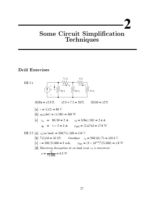
2Some Circuit Simpli¯cationTechniquesDrill ExercisesDE2.116k64=12:8−;12:8+7:2=20−;20k30=12−[a]v=5(12)=60V[b]p5A(del)=(5)(60)=300W[c]i A=60=30=2A i C=3(64)=(80)=2:4Ai B=5¡2=3A p10−=(2:4)210=57:6WDE2.2[a]v o(no load)=200(75)=100=150V[b]75k150=50k−,therefore v o=200(50)=75=133:3V[c]i=200=25;000=8mA,p25k=(8£10¡3)2(25;000)=1:6W[d]Maximum dissipation at no load since v o is maximump=v2o75;000=0:3W2728CHAPTER2.Some Circuit Simpli¯cation TechniquesDE2.3v30=6+4(0:825)=9:3V;i30=v3030=0:31Ai6=i30+0:825=1:135A;i10=0:825+0:31=1:135A¡v30¡6i b+v20¡10i10=0¢::v20=9:3+16(1:135)=27:46Vi20=27:4620=1:373A;i5=i6+i20=2:508Ai30=0:31A;i6=1:135A;i10=1:135A;i20=1:373A;and i5=2:508ADE2.4Problems29i =7212=6A [a]v =7212(8)=48V ;i 120V =120¡57:620=3:12A [b]v a =6(9:6)=57:6V ;p 120V (del)=120i a =374:40WDE 2.5[a]110V source actingalone:R e =10(14)24=356−i 0=1105+35=6=13213Av 0o=µ356¶µ13213¶=77013V 4A source actingalone:5−k 10−=50=15=10=3−10=3+2=16=3−30CHAPTER2.Some Circuit Simpli¯cation Techniques 16=3k12=48=13−Hence our circuit reduces to:It follows thatv00a=4(48=13)=(192=13)Vandv00o=¡v00a(16=3)(10=3)=¡58v00a=¡(120=13)V¢::v o=v0o+v00o=77013¡12013=50V[b]p=v2o10=250WDE2.670-V source acting alone:v0=70¡4i0bi0s=v0b2+v010=i0a+i0b70=20i0a+v0bi0a=70¡v0b 20Problems31¢::i 0b=v 0b 2+v 010¡70¡v 0b 20=1120v 0b +v 010¡3:5v 0=v 0b+2i 0b ¢::v 0b =v 0¡2i 0b¢::i 0b =1120(v 0¡2i 0b )+v 010¡3:5or i 0b =1342v 0¡7042¢::v 0=70¡4µ1342v 0¡7042¶orv 0=322094=161047V 50-V source actingalone:v 00=¡4i 00bv 00=v 00b +2i 00bv 00=¡50+10i 00d ¢::i 00d=v 00+5010i 00s =v 00b 2+v 00+5010i 00b=v 00b 20+i 00s =v 00b 20+v 00b 2+v 00+5010=1120v 00b +v 00+5010v 00b =v 00¡2i 00b¢::i 00b =1120(v 00¡2i 00b )+v 00+5010or i 00b =1342v 00+10042Thus,v 00=¡4µ1342v 00+10042¶orv 00=¡20047V Hence,v =v 0+v 00=161047¡20047=141047=30V32CHAPTER2.Some Circuit Simpli¯cation Techniques ProblemsP2.1[a]p4−=i2s4=(12)24=576W p18−=(4)218=288W p3−=(8)23=192W p6−=(8)26=384W[b]p120V(delivered)=120i s=120(12)=1440W[c]p diss=576+288+192+384=1440WP2.2[a]From Ex.3-1:i1=4A,i2=8A,i s=12Aat node x:¡12+4+8=0,at node y:12¡4¡8=0[b]v1=4i s=48V v3=3i2=24Vv2=18i1=72V v4=6i2=48Vloop abda:¡120+48+72=0;loop bcdb:¡72+24+48=0;loop abcda:¡120+48+24+48=0P2.31R eq=16+110+115=1030=13;R eq=3−v(2+8+5)−=(20)(3)=60V;i(2+8+5)−=60=15=4A P5−=(4)2(5)=80WP2.4[a]R eq=2+2+(1=4+1=5+1=20)¡1=6−i g=120=6=20Av4−=120¡(2+2)20=40Vi o=40=4=10AProblems33 i(15+5)−=40=(15+5)=2Av o=(5)(2)=10V[b]i15−=2A;P15−=(2)2(15)=60W[c]P120V=(120)(20)=2:4kWP2.5[a]R eq=R k R=R22R=R2[b]R eq=R k R k R k¢¢¢k R(n R's)=R kR n¡1=R2=(n¡1)R+R=(n¡1)=R2nR=Rn[c]One solution:700−=200−+500−=1000=5+1000=2=1k−k1k−k1k−k1k−k1k−+1k−k1k−[d]One solution:5:5k−=5k−+0:5k−=2k−+2k−+1k−+0:5k−=2k−+2k−+2k−2+2k−4=2k−+2k−+2k−k2k−+2k−k2k−k2k−k2k−34CHAPTER2.Some Circuit Simpli¯cation TechniquesP2.6[a]12−k24−=8−Therefore,R ab=8+2+6=16−[b]1R eq=124k−+130k−+120k−=15120k−=18k−R eq=8k−;R eq+7=15k−1R ab=115k−+130k−+115k−=530k−=16k−R ab=6k−P2.7[a]For circuit(a)R ab=15k(18+48k16)=10−For circuit(b)1 R e =120+115+120+14+112=3060=12R e=2−R e+16=18−18k18=9−R ab=10+8+9=27−For circuit(c)48k16=12−12+8=20−20k30=12−12+18=30−30k15=10−10+10+20=40−R ab=40k60=24−[b]P a=20210=40WP b=144227=768WP c=62(24)=864WProblems35P2.8[a]5k20=100=25=4−5k20+9k18+10=20−9k18=162=27=6−20k30=600=50=12−R ab=5+12+3=20−[b]5+15=20−30k20=600=50=12−20k60=1200=80=15−3k6=18=9=2−15+10=25−3k6+30k20=2+12=14−25k75=1875=100=18:75−26k14=364=40=9:1−18:75+11:25=30−R ab=2:5+9:1+3:4=15−[c]3+5=8−60k40=2400=100=24−8k12=96=20=4:8−24+6=30−4:8+5:2=10−30k10=300=40=7:5−45+15=60−R ab=1:5+7:5+1:0=10−P2.9[a]R cond=845(0:0397)=33:5465−R total=2(1=2)R cond=33:5465−P loss=(2000)2(33:5465)=134:186MWP calif=800(2)¡134:186=1465:814MWE±ciency=(1465:814=1600)£100=91:61%[b]P calif=2000¡134:86=1865:814MWE±ciency=93:29%[c]P loss=(3000)2¢2¢(1=3)¢845¢(0:0397)=201:279MWP oregon=3000MW;P calif=3000¡201:279=2798:7MWE±ciency=(2798:70=3000)£100=93:29%P2.10i10k=(18)(15)40=6:75mAv15k=¡(6:75)(15)=¡101:25V i3k=18¡6:75=11:25mAv12k=¡(12)(11:25)=¡135Vv o=¡101:25¡(¡135)=33:75V36CHAPTER 2.Some Circuit Simpli¯cation TechniquesP 2.11[a]v 1k =11+5(30)=5V v 15k =1515+60(30)=6Vv x =v 15k ¡v 1k =6¡5=1V [b]v 1k =v s6(1)=v s =6v 15k=v s75(15)=v s =5v x =(v s =5)¡(v s =6)=v s =30P 2.1260k 30=20−i 30−=(25)(75)125=15A v o =(15)(20)=300V v o +30i 30=750V v g ¡12(25)=750v g =1050VP 2.135−k 20−=4−;4−+6−=10−;10k 40=8−;Therefore,i g =1258+2=12:5A i 6−=(40)(12:5)50=10A;i o =(5)(10)25=2A P 2.14[a]40k 10=8−i 75V =7510=7:5A 8+7=15−i 4+3−=7:5µ3045¶=5A15k 30=10−i o =¡5µ1050¶=¡1A[b]i 10−=i 4+3−+i o =5¡1=4AP 10−=(4)2(10)=160WP2.15[a]v9−=(1)(9)=9Vi2−=9=(2+1)=3Ai4−=1+3=4A;v25−=(4)(4)+9=25Vi25−=25=25=1A;i3−=i25−+i9−+i2−=1+1+3=5A;v40−=v25−¡v3−=25¡(¡5)(3)=40Vi40−=40=40=1Ai5k20−=i40−+i25−+i4−=1+1+4=6Av5k20−=(4)(6)=24Vv32−=v40−+v5k20−=40+24=64Vi32−=64=32=2A;i10−=i32−+i5k20−=2+6=8Av g=10(8)+v32−=80+64=144V:[b]P20−=(v5k20−)220=24220=28:8WP2.16[a]Let i s be the current oriented down through the resistors.Then,i s=V sR1+R2+¢¢¢+R k+¢¢¢+R nandv k=R k i s=R kR1+R2+¢¢¢+R k+¢¢¢+R nV s[b]i s=2005+15+30+10+40=2Av1=2(5)=10V v2=2(15)=30V v3=2(30)=60V v4=2(10)=20V v5=2(40)=80VP2.17[a]v o=2525(20)=20V[b]v o=255+R eR eR e=(20)(12)32=7:5k−v o=2512:5(7:5)=15V[c]v o25=2025=0:80[d]v o25=1525=0:60P2.18[a]No load:v o=R2R1+R2V s=¾V s¢::¾=R2R1+R2 Load:v o=R eR1+R eV s=¯V s¢::¯=R eR e+R1R e=R2R LR2+R L¢::¯=R2R LR1R2+R L(R1+R2)But R1+R2=R2¾¢::R1=R2¾¡R2¢::¯=R2R LR2³R2¾¡R2´+R L R2¾¯=R LR 2³1¾¡1´+R L ¾or ¯R 2µ1¾¡1¶+¯R L ¾=R L ¯R 2µ1¾¡1¶=R L Ã1¡¯¾!¢::R 2=(¾¡¯)¯(1¡¾)R LR 1=(1¡¾)¾R 2=þ¡¯¾¯!R L[b]R 1=(0:9¡0:7)0:63(126)k −=40k −R 2=(0:9¡0:7)(0:7)(0:1)(126)k −=360k −P 2.19[a]Let v o be the voltage across the parallel branches,positive at the upperterminal,theni g =v o G 1+v o G 2+¢¢¢+v o G N =v o (G 1+G 2+¢¢¢+G N )It follows thatv o =i g(G 1+G 2+¢¢¢+G N )The current in the k th branch is i k =v o G k ;Thus,i k =i g G k[G 1+G 2+¢+G N ][b]i 6:25=1142(0:16)[4+0:4+1+0:16+0:1+0:05]=32mAP 2.20R e =48£103=500−¢::XG =1500=2mS i 1=2i 2=2(10i 3)=20i 4i 2=10i 3=10i 4i 3=i 48=20i4+10i4+i4+i4=32i4¢::i4=832=0:25mAR4=v gi4=40:25£10¡3=16k−i3=i4=0:25mA ¢::R3=16k−i2=10i4=2:5mAR2=v gi2=42:5£10¡3=1:6k−i1=20i4=5mAR1=v gi1=45£10¡3=800−P2.21[a]i o=120=40k−=3mA[b]v a=(3)(20)=60Vi a=v a100=0:6mAi b=4¡3:6=0:4mAv b=60¡(0:4)(15)=54Vi g=0:4¡54=30=¡1:4mAp75V(developed)=(75)(1:4)=105mWCheck:p4mA(developed)=(60)(4)=240mWX P dev=105+240=345mWX P dis=(¡1:4)2(15)+(1:8)2(30)+(0:4)2(15)+(0:6)2(100)+(3)2(20)=345mWP2.22Apply source transformations to both current sources to geti o=¡66=¡1mAP2.23[a]¢::v o=1(240)=120V;i o=120=24=5A2[b]p300V=¡12:5(300)=¡3750WTherefore,the300V source is developing3.75kW.[c]¡10+i6−+7:5¡12:5=0;¢::i6−=15Av10A+4(10)+6(15)=0;¢::v10A=¡130Vp10A=10v10A=¡1300WTherefore the10A source is developing1300W.[d]X p dev=3750+1300=5050Wp4−=100(4)=400Wp40−=(7:5)2(40)=2250Wp6−=(15)2(6)=1350Wp42−=(5)2(42)=1050WX p diss=400+1350+2250+1050=5050W(CHECKS)P2.24Applying a source transformation to each current source yieldsNow combine the20V and10V sources into a single voltage source and the5−,4−and1−resistors into a single resistor to getNow use a source transformation on each voltage source,thuswhich can be reduced to¢::i o=(1:25)(8)=1A10P2.25First,¯nd the Th¶e venin equivalent with respect to R o.P2.26100−k25−=20−¢::i=400=5A60+20v0o=20i=100V100−k60−=37:5−i=50025+37:5=8Av00o=37:5i=300Vv o=v0o+v00o=100+300=400V P2.27i0o=10025=4A15−k30−=10−i00o=¡5025=¡2A¢::i o=i0o+i00o=4¡2=2A P2.2815=2i0¢+50i1+3i0¢Problems4715=2i 0¢+12i 02i 0¢=i 01+i 02;i 01=27=26A;i 0¢=51=26A¢::i 02=1213A;v 0o=9613V ¡2i 00¢=5i 001+3i 00¢¢::i 00¢=¡i 001i 002=i 00¢¡i 001=2i 00¢4i 002+(8+i 002)8=¡2i 00¢¢::i 002=¡6413A;i 001=3213A;i 00¢=¡3213A ¢::8+i 002=4013A ¢::v 00o=8µ4013¶=32013V ¢::v o =v 0o +v 00o =9613+32013=32V48CHAPTER2.Some Circuit Simpli¯cation TechniquesP2.29[a]The evolution of the circuit shown in Fig.P2.29is illustrated in the following steps:[b]Starting at the left end of the circuit and working toward the right end,aseries of source transformations yields:Problems49V R=4 4R (2R)=V R8P2.30[a]The evolution of the circuit in Fig.P2.30can be shown in two steps,thus:[b]Moving from left to right,a series of source transformations yields:50CHAPTER2.Some Circuit Simpli¯cation Techniquesv o=V R=84R(2R)=V R16Problems51 P2.31Eq.(2.34)v o=12V R(Switch1)Eq.(2.35)v o=14V R(Switch2)Eq.(2.36)v o=18V R(Switch3)Eq.(2.37)v o=116V R(Switch4)Given V R=16V:Switch Position v o12340000v o=0V000V R v o=116V R=1V00V R0v o=18V R=2V00V R V R v o=116V R+18V R=3V0V R00v o=14V R=4V0V R0V R v o=14V R+116V R=5V0V R V R0v o=14V R+18V R=6V0V R V R V R v o=14V R+18V R+116V R=7VV R000v o=12V R=8VV R00V R v o=12V R+116V R=9VV R0V R0v o=12V R+18V R=10VV R0V R V R v o=12V R+18V R+116V R=11VV R V R00v o=12V R+14V R=12VV R V R0V R v o=12V R+14V R+116V R=13VV R V R V R0v o=12V R+14V R+18V R=14VV R V R V R V R v o=12V R+14V R+18V R+116V R=15V52CHAPTER2.Some Circuit Simpli¯cation TechniquesThis page intentionally left blank。
电路分析基础FundamentalsofElectricCircuits
第三章
叠加方法 与
网络函数
第四章
分解方法 及
单口网络
2019/11/27
7
第二篇 动态电路的时域分析
第五章 电容元件
与 电感元件
第六章 一阶电路
第七章 二阶电路
2019/11/27
8
第三篇 动态电路的相量分析法和s域分析法
第八章
阻抗和导纳
引言
第九章
正弦稳态功率和能量 三相电路
第十章
频率响应 多频正弦稳态电路
11
• 教学方式:讲课、作业、答疑 • 答疑时间:每周三上午 • 答疑地点:信息工程学院楼428 • 教学要求: 认真听讲、积极思考、及时复习 • 学时: 72 学分: 4 • 学习方法: • 重点掌握基本概念、基本定律、基本分析方法 • 抓住知识点之间的内在联系,进行阶段小结 • 多做练习、举一反三、熟能生巧
• 通过本课程的学习,学生不但能获得电路分析的基本知
识,而且可以在抽象思维能力,分析计算能力,总结归 纳能力和实验动手能力诸方面得到提高。
• 本课程的先修课程是《高等数学》和《大学物理》。
2019/11/27
10
数字电路 基础与应用
半导体基础和基本放大电路
电路分析基本理论 和基本分析方法
2019/11/27
2
(1) 课程任务
• 学习电路分析所需要的基本原理
叠加、分解、变换域三大基Leabharlann 方法KCL、KVL 和 VCR
两类约束
集总电路
一个假设
2019/11/27
3
(2) 课程地位
先修课程
高等数学 物理
后续课程
信号与系统 电子电路
2019/11/27
电路基础第一章英文版chapter1PPT课件
6
Electric current i = dq/dt. The unit of current is the ampere (A),
and it can be derived as 1 A = 1C/s. • A direct current (dc) is a current that
remains constant with time. • An alternating current (ac) is a
Basic unit meter
kilogram second ampere kelvin
mole candela
Symbol m Kg s A K
mol cd
3
The derived units commonly used in electric circuit theory
Decimal multiples and submultiples of SI units 4
11
We should pay close attention to that the arrow is a fundamental part of the definition of the current! Thus, to talk about the value of a current i (t) without specifying the arrow is to discuss an undefined entity. For example, Fig. 1.3a is the proper definitive, whereas Fig. 1.3b apresentation of i(t) symbology.
电路分析师作文英语

电路分析师作文英语Title: The Role and Responsibilities of a Circuit Analyst。
Introduction:Circuit analysis is a crucial aspect of electrical engineering, playing a vital role in ensuring the functionality, efficiency, and safety of electronic systems. As a circuit analyst, one undertakes the responsibility of scrutinizing, designing, and optimizing circuits to meet specific requirements. In this essay, we delve into therole and responsibilities of a circuit analyst,highlighting the skills and knowledge required to excel in this field.Understanding Circuit Analysis:Circuit analysis involves the examination of electrical circuits to understand their behavior and performance. Itencompasses various techniques and methodologies to analyze voltage, current, power, and other electrical parameters within a circuit. A circuit analyst employs mathematical models, simulation software, and testing equipment to assess circuit performance accurately.Responsibilities of a Circuit Analyst:1. Circuit Design:One of the primary responsibilities of a circuit analyst is to design electrical circuits that meet predetermined specifications. This involves understanding the functional requirements of the circuit, selecting appropriate components, and arranging them to achieve the desired outcome. Circuit analysts must possess a deep understanding of circuit theory, semiconductor devices, and analog/digital electronics to create effective designs.2. Simulation and Analysis:Circuit analysts utilize simulation software such asSPICE (Simulation Program with Integrated Circuit Emphasis) to model and analyze circuit behavior. Through simulation, analysts can predict how a circuit will perform under different operating conditions, identify potential issues, and optimize circuit parameters for improved performance. Proficiency in simulation tools is essential for accurately assessing circuit behavior and making informed design decisions.3. Troubleshooting and Debugging:When confronted with malfunctioning circuits or unexpected behavior, circuit analysts must possess strong troubleshooting skills to identify and rectify faults. This involves systematic analysis of circuit components, signal waveforms, and electrical parameters to isolate the root cause of the problem. Effective troubleshooting requires a combination of theoretical knowledge, practical experience, and attention to detail.4. Performance Optimization:Circuit analysts are responsible for optimizing circuit performance in terms of efficiency, reliability, and cost-effectiveness. This may involve refining circuit parameters, selecting alternative components, or redesigning circuitry to achieve desired performance metrics. Optimization efforts aim to enhance circuit functionality while minimizing resource utilization and mitigating potential risks.5. Compliance and Standards:Ensuring compliance with industry standards, regulations, and safety protocols is a critical aspect of the circuit analyst's role. Analysts must stay abreast of relevant standards such as IEEE, IEC, and NEC to ensurethat their designs meet legal and safety requirements. Adherence to standards not only ensures the reliability and integrity of circuits but also fosters trust among stakeholders.Skills and Qualifications:To excel as a circuit analyst, individuals should possess a combination of technical expertise, problem-solving abilities, and communication skills. Some essential skills and qualifications include:Proficiency in circuit theory, semiconductor physics, and analog/digital electronics.Experience with simulation software and circuit analysis tools.Strong analytical and critical thinking skills.Effective communication and teamwork abilities.Attention to detail and a methodical approach to problem-solving.Knowledge of industry standards and regulatory requirements.Conclusion:In conclusion, the role of a circuit analyst is multifaceted, encompassing design, analysis, optimization, and troubleshooting of electrical circuits. By leveraging their technical expertise and problem-solving skills, circuit analysts play a pivotal role in the development of reliable and efficient electronic systems. With the continuous evolution of technology, the demand for skilled circuit analysts remains high, making it an exciting and rewarding career path for aspiring electrical engineers.。
电路基础英文版精编版第六版课程设计

电路基础英文版精编版第六版课程设计1. IntroductionElectricity is an essential component of modern life, powering homes, businesses, and industries around the globe. Understanding the basics of electric circuits is therefore a critical skill for anyone interested in pursuing a career in the electrical or electronics fields. The Circuits Fundamentals course is designed to provide students with an in-depth understanding of electric circuits.This document outlines a course design for the sixth edition of the Electric Circuits Fundamentals textbook, a well-known and widely-used resource for undergraduate students studying electrical and electronics engineering.2. Course ObjectivesThe primary objective of this course is to provide students with a comprehensive understanding of the fundamental principles of electric circuits. By the end of the course, learners will be able to:•Design, analyze, and interpret electric circuits using standard tools and techniques.•Understand the physical principles that underpin electric circuits, and how these principles relate toreal-world applications.•Effectively communicate their understanding of electric circuits to others, both in written and oralformats.3. Course OutlineThe Circuits Fundamentals course comprises 14 chapters, covering a wide range of topics related to electric circuits. The following table provides an overview of the course structure:Chapter Topic Learning Objectives1 Basic Concepts To introduce the fundamentalconcepts of electric circuits2 Resistance andOhm’s Law To understand the resistance and its relationship with Ohm’s Law3 Energy and Power inCircuits Get to know energy concepts and power dissipation in circuits4 Series Circuits Understand the properties andanalyze the behavior of seriescircuits5 Parallel Circuits Understand the properties andanalyze the behavior of parallelcircuits6 Series-ParallelCircuits Understand the properties and analyze the behavior of series-parallel circuits7 Circuits withCapacitors Get to know the properties and behavior of circuits with capacitors8 Circuits withInductors Get to know the properties and behavior of circuits with inductors9 Circuits withCapacitors andInductors Understand the behavior of circuits with capacitors and inductors10 Frequency Response Understand the frequency and itsresponse in circuit elements11 AC Power Understand the properties ofalternating current power12 Three-PhaseCircuits Understand the principles and usage of three-phase circuits13 Transformers Understand the behavior andprinciples of transformers14 Circuit Analysisusing SPICESoftware Understand the usage and implementation of SPICE software4. Course Materials4.1 Required TextbookThe required textbook for this course is the sixth edition of the Electric Circuits Fundamentals textbook. This resource provides a comprehensive overview of the topics covered in the course and includes a range of helpful examples, exercises, and review questions to support learning.4.2 Required HardwareStudents will also need access to the following hardware: • A computer or laptop with appropriate software for circuit simulation, such as the SPICE software.•Basic tools for building and testing circuits, including multimeters, signal generators, andoscilloscopes.5. Course AssessmentStudent learning in this course will be assessed through a combination of homework assignments, quizzes, and exams.Homework assignments will be given regularly to reinforce key concepts introduced in each chapter. Quizzes will be given throughout the course to assess student understanding of specific topics, while exams will be given at the end of the course to evaluate overall knowledge and understanding.6. ConclusionThe Circuits Fundamentals course provides students with a comprehensive understanding of electric circuits and their applications. By completing this course, learners will develop a deep understanding of the fundamental principles of electric circuits, as well as the ability to apply this knowledge to real-world situations.。
电路基础理论英文版课件Chapter 9
Chapter 9 Sinusoids and PhasorsSinusoidsA sinusoid is a signal that has the form of the sine or cosine function.anglephase um ent t frequencyangular am plitudeVm where t V v m ==+==+=φφϖϖφϖarg )cos()cos(φϖ+=t V v m φωtfTππω22==radians/second (rad/s)f is in hertz(Hz))cos()()cos()(222111φωφω+=+=t V t v t V t v m m Phase difference:φθφθθθφφφωφωθby v lags v by v leads v phase in are v and v phaseof out are v and v if t t 210210210210)()(2121<>=≠-=+-+=Complex Numberforml exponentia form sinusoidal formpolar form r rectangula φφφφj rez jrsin rcos z r z jy x z =+=∠=+=φPhasora phasor is a complex number representing the amplitude and phase angle of a sinusoidal voltage or current.Eq.(8-1)and Eq. (8-2) Eq.(8-3)When Eq.(8-2) is applied to the general sinusoid we obtainE q.(8-4)The phasor V is written asEq.(8-5)Fig. 8-1 shows a graphical representation commonly calleda phasor diagram.Fig. 8-1: Phasor diagram Two features of the phasor concept need emphasis:1.Phasors are written in boldfacetype like V or I1 to distinguishthem from signal waveformssuch as v(t)and i1(t).2. A phasor is determined byamplitude and phase angle anddoes not contain anyinformation about the frequencyof the sinusoid.In summary, given a sinusoidal signal , the corresponding phasor representation is . Conversely, given the phasor , the corresponding sinusoid is found by multiplying the phasor by and reversing the steps in Eq.(8-4) as follows:E q.(8-6))cos()(φϖ+=t V t v m φ∠=Vm V Time domainrepresentationPhase-domain representationProperties of Phasors•additive propertyEq.(8-7)Eq.(8-8)Eq.(8-9)•derivative propertyEq.(8-10)Vj dtdv ω⇔∴Time domain representationPhase-domain representation•Integral propertyTime domain representationPhase-domainrepresentation⎰⇔ωj Vvdt The differences between v(t) and V:V(t) is the instantaneous or time-domain representation, while V is the frequency or phasor-domain representation.2.V(t) is a real signal which is time dependent, while V is just a supposed value to simplify the analysisThe complex exponential is sometimes called a rotating phasor, and the phasor V is viewed as a snapshot of the situation at t=0.Fig. 8-2: Complex exponential+ j + real-real-j ωtV mθ= 0θ= 90 or π/2θ= -90 or -π/2θ= 180 or π151050510151513.51210.597.564.531.5010V r ms ac signal at 0.5 Hzvoltage in voltsa n g u l a r f r e q u e n c y t i m e s t i m e i n r a d i a n s12.566-ω-t n⋅14.14214.142-v rea l t ()n5101515129630369121510V rms ac signal at 0.5 Hzangular frequency times time in radiansV o l t a g e i n v o l t s14.14214.142-v im a g t n ()12.5660ωt ⋅()n)sin(is axis )(imaginary j on the phasor rotating the of projection The t V v m ima g ω⋅=)cos(is axis real on the phasor rotating the of projection The t V v m rea l ω⋅=()()caseparticular In this 5.02cos 102cos t t f V v m ⋅⋅=⋅⋅=ππEXAMPLE 8-1(a)Construct the phasors for the following signals:(b) Use the additive property of phasors and the phasorsfound in (a) to find v(t)=v1(t)+v2(t).SOLUTION(a) The phasor representations of v(t)=v1(t)+ v2(t) are(b) The two sinusoids have the same frequent so the additive property of phasors can be used to obtain their sum:The waveform corresponding to this phasor sum isV1V21jVEXAMPLE 8-2(a)Construct the phasors representing the following signals:(b) Use the additive property of phasors and the phasors foundin (a) to find the sum of these waveforms.SOLUTION:(a) The phasor representation of the three sinusoidal currents are(b) The currents have the same frequency, so the additive property of phasors applies. The phasor representing the sum of these current isFig. 8-4EXAMPLE 8-3Use the derivative property of phasors to find the time derivative of v(t)=15cos(200t-30°).The phasor for the sinusoid is V=15∠-30 °.According tothe derivative property, the phasor representing the dv/dt isfound by multiplying V by jω.SOLUTION:The sinusoid corresponding to the phasor jωV isDevice Constraints in Phasor FormV oltage-current relations for a resistor in the: (a) time domain, (b) frequency domain.Resistor:RejImI VIV m m RI Vφφ==Device Constraints in Phasor FormInductor:V oltage-current relations for an inductor in the: (a) time domain, (b) frequency domain.ω︒+==90I V mm LI V φφωDevice Constraints in Phasor Form Capacitor:ωV oltage-current relations for a capacitor in the: (a) time domain, (b) frequency domain.︒+==90VImmCVIφφωConnection Constraints in Phasor Form KVL in time domainKirchhoff's laws in phasor form (in frequency domain)KVL: The algebraic sum of phasor voltages around a loop iszero.KCL: The algebraic sum of phasor currents at a node is zero.The IV constraints are all of the formV=ZI or Z= V/IEq.(8-16)where Z is called the impedance of the elementThe impedance Z of a circuit is the ratio of the phasor voltage V to the phasor current I, measured in ohms(Ω)reactance. the is Z Im X and resistance the is Z Re R where ==+=jXR Z The impedance is inductive when X is positiveis capacitive when X is negativeθθθθsin,cos tan, where 122Z X Z R and RXX R Z Z Z ===+=∠=-EXAMPLE 8-5Fig. 8-5The circuit in Fig. 8-5 is operating in the sinusoidal steady state with and . Find the impedance of the elements in the rectangular box.SOLUTION:︒VI0.278/R=37.9-∠=3L2The Admittance ConceptThe admittance Y is the reciprocal of impedance, measured in siemens (S)VI Z Y ==1Y=G+jBWhere G=Re Y is called conductance and B=Im Y is called the susceptance 2222,1XR XB X R R G jX R jB G +-=+=+=+How get Y=G+jB from Z=R+jX ?Cj Y capacitor Lj Y inductor GR Y resistor C L R ωω====:1:1:Basic Circuit Analysis with PhasorsStep 1: The circuit is transformed intothe phasor domain by representing theinput and response sinusoids as phasorand the passive circuit elements bytheir impedances.Step 2: Standard algebraic circuittechniques are applied to solve thephasor domain circuit for the desiredunknown phasor responses.Step 3: The phasor responses areinverse transformed back into time-domain sinusoids to obtain theresponse waveforms.Series Equivalence And Voltage Divisionwhere R is the real part and X is the imaginary partEXAMPLE 8-6Fig. 8-8The circuit in Fig. 8 -8 is operating in the sinusoidal steady state with(a) Transform the circuit into the phasor domain.(b) Solve for the phasor current I.(c) Solve for the phasor voltage across each element.(d) Construct the waveforms corresponding to the phasors found in (b) and (c)SOLUTION:PARALLEL EQUIVALENCE AND CURRENT DIVISIONRest ofthecircuitY1Y1Y2Y NIVI1I2I3 phasor version of the current division principleEXAMPLE 8-9Fig. 8-13The circuit in Fig. 8-13 is operating in the sinusoidal steady state with i S(t)=50cos2000t mA.(a) Transform the circuit into the phasor domain.(b) Solve for the phasor voltage V.(c) Solve for the phasor current through each element.(d) Construct the waveforms corresponding to the phasors found in (b) and (c).SOLUTION:(a) The phasor representing the input source current isIs=0.05∠0°A. The impedances of the three passive elements areFig. 8-14And the voltage across the parallel circuit isThe sinusoidal steady-state waveforms corresponding to thephasors in (b) and (c) areThe current through each parallel branch isEXAMPLE 8-10Fig. 8-15Find the steady-state currents i(t), and i C(t)in the circuit of Fig. 8-15 (for Vs=100cos2000t V, L=250mH, C=0.5 μF, and R=3kΩ).SOLUTION:Vs=100∠0°Y←→△TRANSFORMATIONSThe equations for the △to Ytransformation areThe equations for a Y-to-△transformation arewhen Z1=Z2=Z3=Z Y or Z A=Z B=Z C=Z N.Z Y=Z N/3 and Z N=3Z Y balanced conditionsEXAMPLE 8-12Use a △to Y transformation to solve for the phasor current I X in Fig. 8-18.Fig. 8-18SOLUTION:ABC△to Y。
电路基础理论英文版课件第一章

Resistance is measured in ohms (Ω) using a ohmmeter.
Definition
Definition
Capacitance is the ability of a capacitor to store electrical energy. It is measured by the capacity of the capacitor to hold a charge.
详细描述
04
Analysis methods for circuits
单击此处添加正文,文字是您思想的提炼,为了最终呈现发布的良好效果,请尽量言简意赅的阐述观点;单击此处添加正文,文字是您思想的提炼,为了最终呈现发布的良好效果,请尽量言简意赅的阐述观点;单击此处添加正文,文字是您思想的提炼,为了最终呈现发布的良好效果,请尽量言简意赅的阐述观点;单击此处添加正文 10*16
A circuit that allows the flow of AC current, typically used in household and industrial applications.
பைடு நூலகம்
Definition of Circuit
Components
01
Circuit components include resistors, capacitors, inductors, diodes, transistors, and power sources. These components are connected to form a complete circuit.
contents
目 录
电路分析基础英文版课程设计
IntroductionCircuit analysis is the process of solving mathematical equations in order to determine how electric current flows in a circuit. It is an essential skill for anyone interested in electronic design, as it allows us to predict the performance of a circuit before it is built, saving time and resources. In this document, we will be discussing the foundational principles of circuit analysis and circuits in general, in the context of an English-language course.ObjectivesThe objectives of this course are to:•Learn the fundamental principles of circuits, including voltage, current, resistance, and power•Understand how to apply Ohm’s law and Kirchhoff’s laws to analyze simple circuits•Gn familiarity with circuit elements such as resistors, capacitors, and inductors, and how they affect circuit behavior •Explore more complex circuits, including those contning voltage and current sources and those with multiple loops andnodes•Learn how to use simulation software to predict circuit performance.TopicsUnit 1: Introduction to Circuits•Definition of a circuit: series and parallel circuits.•Basic circuit elements: voltage sources, resistors, capacitors, and inductors.•Voltage, current, resistance, and power: Ohm’s law and its application.Unit 2: Circuit Analysis Techniques•Kirchhoff’s voltage law and Kirchhoff’s current law.•Circuit analysis using nodal and mesh analysis.•Superposition principle and Thevenin’s theorem.Unit 3: Capacitors and Inductors•Capacitors: capacitance, charge, voltage, current, and energy storage.•Inductors: inductance, magnetic field, voltage, current, and energy storage.•Series and parallel combination of capacitors and inductors. Unit 4: AC Circuits•AC voltage and current: peak, root mean square, and average values.•Sinusoidal waveforms: equations, phasors, and frequency domn analysis.•AC circuits contning resistors, capacitors, and inductors: impedance, admittance, and phase angle.Unit 5: More Complex Circuits•Voltage and current sources: DC and AC sources, independent and dependent sources.•Circuit analysis with multiple loops and nodes: nodal and mesh analysis.•Maximum power transfer theorem and impedance matching.Unit 6: Circuit Simulation•Introduction to simulation software: Circuit Simulator, LTSpice, and MATLAB.•Simulation of basic and intermediate circuits.•Circuit simulation using MATLAB live scripts.AssessmentThe course will be assessed through a combination of in-class participation, homework assignments, and exams. Homework problems willbe assigned regularly and graded for accuracy and completeness. Examswill cover the material discussed in class and in the homework assignments. In-class participation will be assessed based on attendance, active participation in class discussions, and engagement with class material.ConclusionThis course provides a foundation in circuit analysis that is essential for anyone interested in electronic design. By emphasizing the fundamental principles of circuits and the methods used to analyze them,students will gn a deeper understanding of circuit behavior and be better equipped to design and troubleshoot electronic circuits.。
- 1、下载文档前请自行甄别文档内容的完整性,平台不提供额外的编辑、内容补充、找答案等附加服务。
- 2、"仅部分预览"的文档,不可在线预览部分如存在完整性等问题,可反馈申请退款(可完整预览的文档不适用该条件!)。
- 3、如文档侵犯您的权益,请联系客服反馈,我们会尽快为您处理(人工客服工作时间:9:00-18:30)。
Prof. C.K. Tse: Basic Circuit
Analysis
18
Star-to-delta conversion
Y (star)
For the Y circuit, we consider summing up all currents into the centre node: I1+I2+I3=0, where
3
Power and energy
Work done in moving a charge dq from A to B having a potential difference of V is
W = V dq
A
dq
B
Power is work done per unit time, i.e.,
Prof. C.K. Tse: Basic Circuit
Analysis
15
Example (something that can be done with series/parallel reduction)
Consider this circuit, which is created deliberately so that you can solve it using series/parallel reduction technique. Find V2. Solution: Resistance seen by the voltage source is
Is there some ad hoc solution?
Prof. C.K. Tse: Basic Circuit
Analysis
17
Equivalence of star and delta
Y (star)
D (delta)
Problems: 1. Given a star circuit, find the delta equivalence. That means,
+ assigned to a higher potential point; and – assigned to a lower potential point.
n NOTE: Direction and polarity are arbitrarily assigned on circuit diagrams. Actual direction and polarity will be governed by the sign of the value.
Prof. C.K. Tse: Basic Circuit
Analysis
8
Kirchhoff’s laws
n Kirchhoff’s current law (KCL)
n The algebraic sum of the currents in all branches which converge to a common node is equal to zero.
Prof. C.K. Tse: Basic Circuit
Analysis
2
Units of measurement
n Voltage: volt (V) n Current: ampere (A)
n NOT Volt, Ampere!!
Prof. C.K. Tse: Basic Circuit
Analysis
Thus,
D (delta)
, and
Prof. C.K. Tse: Basic Circuit
Hence, Current division gives:
Then, using V2=I4R4, we get
Prof. C.K. Tse: Basic Circuit
Analysis
16
Oops!
Series/parallel reduction fails for this bridge circuit!
n These wires converge in NODES n The devices are called BRANCHES of the circuit
Circuit Analysis Problem: To find all currents and voltages in the branches of the circuit when the intensities of the sources are known.
suppose you have all the G’s in the star. Find the G’s in the
delta such that the two circuits are “equivalent” from the
external viewpoint. 2. The reverse problem.
For example, if we use R for the parallel circuit, we get the equivalent resistance as
which is more complex than the formula in terms of G:
G = G1 + G2 + … + Gn
An independent voltage source can never be shorted. An independent current source can never be opened.
Prof. C.K. Tse: Basic Circuit
ห้องสมุดไป่ตู้
Analysis
6
Dependent sources
n Dependent sources — values depend on some other variables
Prof. C.K. Tse: Basic Circuit
Analysis
7
Circuit
n Collection of devices such as sources and resistors in which terminals are connected together by conducting wires.
Analysis
9
Overview of analysis
n Ad hoc methods (not general)
n Series/parallel reduction n Ladder circuit n Voltage/current division n Star-delta conversion
n More general
n Mesh and nodal methods
} Done in Basic Electronics!
n Completely general
n Loop and cutset approach (requires graph theory)
NEW
Prof. C.K. Tse: Basic Circuit
Analysis
10
Series/parallel reduction
n Series circuit— each node is incident to just two branches of the circuit
KVL gives
=
Hence, the equivalent resistance is:
Prof. C.K. Tse: Basic Circuit
Analysis
5
Independent sources
n Voltage sources n Current sources
Independent — stubborn! never change!
Maintains a voltage/current (fixed or varying) which is not affected by any other quantities.
We continue to focus on the remaining subcircuit. Eventually we get
Prof. C.K. Tse: Basic Circuit
Analysis
14
Voltage/current division
For the series circuit, we can find the
voltage across each resistor by the
formula:
For the parallel circuit, we can find the
voltage across each resistor by the
formula:
Note the choice of R and G in the formulae!
Prof. C.K. Tse: Basic Circuit
Analysis
11
Series/parallel reduction
n Parallel circuit— one terminal of
each element is connected to a node of the circuit while other terminals of the elements are connected to another node of the circuit
Prof. C.K. Tse: Basic Circuit
Analysis
4
Direction and polarity
n Current direction indicates the direction of flow of positive charge n Voltage polarity indicates the relative potential between 2 points: