moog伺服阀中文样本
MOOG_DDV阀_资料(中文)

MOOGMOOG(穆格)DDV伺服阀MOOG(穆格)D633、D634系列伺服阀是MOOG公司最新研制成功的新型电液伺服阀,目前已由MOOG GmbH(德国)公司进行批量生产。
它是一种直接驱动式伺服阀,简称DDV(Direct Drive Servo Valve的缩写),油口与安装尺寸D633按NG6(Cetop 3),D634按NG10(Cetop 5),用集成电路实现阀芯位置的闭环控制,阀芯的驱动装置是永磁直线力马达。
对中弹簧使阀芯保持在中位,直线力马达克服弹簧的对中力使阀芯在两个方向都可偏离中位,平衡在一个新的位置,这样就解决了比例电磁线圈只能在一个方向产生力的不足之处。
阀芯位置闭环控制电子线路与脉宽调制(PWM)驱动电子线路固化为一块集成块,用特殊的连接技术固定在伺服阀内,因此D633、D634系列伺服阀无需配套电子装置就能对其进行控制。
D633、D634系列伺服阀是MOOG公司对其经久考验,盛名于世的双喷嘴力反馈两级伺服阀的发展与补充,和传统的MOOG30、31、32、34、35、E760等系列伺服阀相比,其最大的区别在于D633、D634系列伺服阀从结构上取消了喷嘴一挡板前置级、用大功率的直线力马达替代了小功率的力矩马达,用先进的集成块与微型位置传感器替代了工艺复杂的机械反馈装置—力反馈杆与弹簧管,从而简化了结构,提高了可靠性,大大地降低了制造成本,却保持了带喷挡前置级的两级伺服阀的基本性能与技术指标。
MOOG DDV伺服阀的特点1.在位置、速度、压力以及力电液伺服系统中可用二位二通、三位三通或三位四通的方式进行工作。
2.安装形式与尺寸符合DIN24340和cetop3与6。
3.无液压前置级。
4.停电、电缆损坏、或者紧急停车情况下伺服阀均能自行回中,无需外力推动。
5.动态性能指标与供油压无关。
6.防水性为IP65(DIN40050)级。
7.低的滞环,高的分辨率。
8.具有极性接反保护功能与超压保护功能。
MOOG穆格D661-G...A中文样本

长寿命使用: ISO 4406 <16/14/11
滤油器精度
推荐值
常规使用: ß15≥ 75(15 μm 绝对值)
长寿命使用: ß10≥ 75(10 μm 绝对值)
安装位置
任意,固定或运动
振动
30 g,三轴
保护等级
符合 EN 60529 标准,带配套插头时防护等级
为 IP 65。
保护底板
发货时随附
流量 Q [l/min]
M 6 x 60 DIN EN ISO 4762-10.9 可更换的滤油器 更换滤滤器用 O 型密封圈
滤油器 滤油器端盖
用于 P、A、B、T、 T2、X 和 Y 口 B67728 001 参见特殊参数表
A03665 060 060 A67999 200
1 个,ID 12 x Ø 2.0 1 个,ID 17.1 x Ø 2.6
本产品目录中所陈述 的伺服阀已完全通 过了欧 洲 电 器 标 准 的 EMC 测试。请参阅电气控 制部分的相关内容。
伺服阀的实际输出流量与输入 的指令电信号和阀的压降有关。
Q = QN
Δp ΔpN
当阀的压降为某一特定值时,负 载 流 量 则与 阀 锐 边节 流口前后 压 降 的 平方 根 成 正 比, 如 右 式 所示:
油液温度
–20°C ~ +80°C
密封圈材料
丁腈橡胶、氟橡胶或根据用户要求提供
工作介质
石油基液压油(DIN 51524 第 1 – 3 部分的标
准),或根据用户要求选用
油液粘度 推荐值
15 ~ 100 mm2/s
允许值
5 ~ 400 mm2/s
系统过滤要求:先导级:选用高压滤油器(无旁通阀,带污物堵
moog伺服阀中文样本
moog伺服阀中文样本:高性能的机电控制Moog伺服阀是一种武器级别的控制技术,以其无与伦比的性能而享誉全球。
其所需的仅仅是电流信号、电源和几个管路连接。
Moog伺服阀能够在自动化过程中精确控制方位、力量和速度,并且能够以无与伦比的响应速度根据要求改变输出角度。
在各种机电传动和控制应用中,Moog伺服阀都可以发挥其无与伦比的性能。
它广泛地应用于空间、国防、电子和机床、机器人和机器人制造、自动化、制药和化学,汽车和交通数量庞大的环境中,带给用户高品质的动力选择。
而且在各种应用程序中,它的高性能使得机电传动逐渐沿着“精准控制”方向不断进步。
Moog伺服阀的安装简便快捷、特性性能稳定、运行可靠、实现精度达到极高,兼容性好,容错能力强。
它具备与工业控制相匹配的变形区域和极高的速度响应能力,而且能够在超高压密封情况下满足用户的高要求。
同时,Moog伺服阀的材料优质,耐用性高,具有极长的寿命和超强的精度和可靠性。
Moog伺服阀的性能和功能是基于数控和计算机控制进行设计的。
这些专用的控制系统在工业自动化、机器人制造、自动化装配、航空航天和军事模拟等应用中得到了广泛的应用。
Moog伺服阀将应用广泛,是因为他不仅提供高性能,而且能够以各种方式使用,使其在加工和机器人制造等轮廓应用中具有卓越性价比,以及在控制和合成等独立环境中,表现出操作简便和优秀的响应速度。
Moog伺服阀可直接在用户的机器上执行,而无需安装控制系统,使得这些设备成为一种极其灵活和具有成本效益的选择。
Moog伺服阀的性能和设计使得其可同时监测若干个物理量并进行同步控制,在精度和反应速度方面得到最佳表现。
单元可以为用户提供旋转速度、位置、力量、加速度和压力等数据,以达到最佳的响应速度。
Moog伺服阀的特性1. 高性能:Moog伺服阀的高性能表现在动力输出精度和响应速度上,是由于其可对管路进行控制,并将输出方位、速度和力量调整到百分之几度以上的位置。
2. 简单的安装和调试:Moog伺服阀可以在不需要预先安装控制系统的情况下直接在用户的设备上恢复其功能,降低了基础设施需求和成本。
Moog Inc. Series 72K 电液伺服阀手册说明书
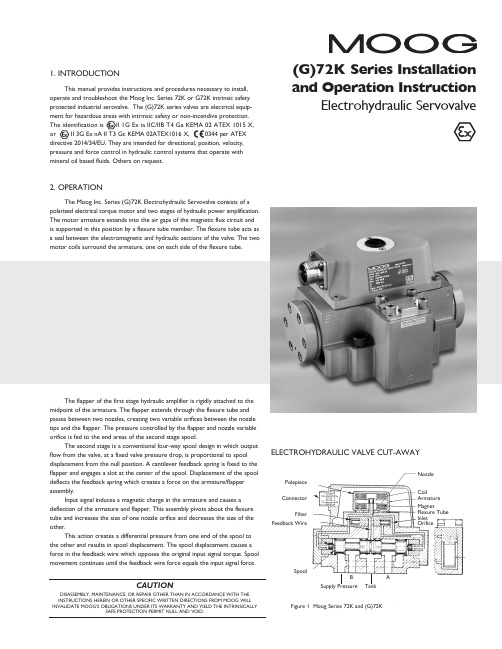
�(G)72K Series Installation ELECTROHYDRAULIC VALVE CUT-AWAYCoilArmature MagnetFlexure Tube Inlet OrificePolepiece ConnectorFilterFeedback WireSpoolFigure 1 Moog Series 72K and (G)72KSupply PressureBTankANozzle3. ELECTRICAL INFORMATION AND INTRINSICALLY SAFE CIRCUIT SAFETY PARAMETERSa. A wide choice of coils is available for a variety of rated currentrequirements. The torque motor coil leads are attached to the connector so external connections can provide series, parallel or single coiloperation. The valves are equipped either with an MS type connector or with pigtail leads for electrical wiring. Refer to installation drawings of the specific model for details. Servovalve coils should be driven with current to provide consistency throughout the temperature range.b. The (G)72K valves are approved for intrinsically safe protection per EN60079-11. The approved safety parameters are listed in the following table for all the coils used by (G)72K series. Coil number is marked on thevalve nameplate.Coil Configuration Marking U i (MAX) I i (MAX) G4220-031 (single, series, parallel) Ex ia IIB T4 12 V 120 mAG4220-051/098 (single, series, parallel) Ex ia IIB T4 12 V 240 mAG4221-001 G4220-042 (single) Ex ia IIC T4 16 V 160 mA G4221-001 G4220-042 (single) Ex ia IIC T4 24.4 V 85 mAG4220-031 (single, parallel) Ex ia IIC T4 30 V 26 mAG4220-031 (series) Ex ia IIC T4 30 V 18 mAG4220-051/098 (single, parallel) Ex ia IIC T4 30 V 19 mA G4220-051/098 (series) Ex ia IIC T4 30 V 12.7 mAG4220-042 (single) Ex ia IIC T4 30 V 37 mAG4220-042 (parallel) Ex ia IIC T4 30 V 20 mAG4220-042 (series) Ex ia IIC T4 30 V 10 mAG4221-001 (single) Ex ia IIC T4 30 V 28 mAc. The (G)72K valves are approved for non-incendive operation for supplycurrent not to exceed 50 mA dc.d. When making electric connections to the valve, appropriate measures mustbe taken to ensure that locally different earth potential do not result inexcessive ground currents. When barriers are required for the hazardous location, hazardous area (field) wiring must meet the requirements ofthe barrier manufacturer. All barriers must be mounted and installed incompliance with the barrier manufacturer’s requirements. Twisted pairs of 18-20 gage wire are recommended. If shielded wire is used, connect shield wire to earth ground only at the barrier strip.4. SPECIAL CONDITIONS FOR SAFE USEBecause the enclosure of the apparatus is made of aluminum, if it is mounted in an area where the use of category 1 G apparatus is required, it must be installed such that even in the event of rare incidents, ignition sources due to impact and friction sparks are excluded.When the electrohydraulic servovalve is used in an application for type of explosion protection intrinsic safety “i”, the appropriate box on the data label must be scored. When the electrohydraulic servovalve is used in an application for type of explosion protection “n”, the appropriate box on the data label must be scored.After use in an application for type of explosion protection “n”, the servovalve cannot abe safely used in a intrinsically safe application.The screwed cable connector may only be disconnected when the circuit is de-energized or when the location is known to be non-hazardous.When used at an ambient temperature ≥70°C, heat resistant cable must be used with a continuous operating temperature in accordance with the application.5. HYDRAULIC SYSTEM PREPARATIONTo prolong servovalve operational life and to reduce hydraulic system maintenance, it is recommended that the hydraulic fluid be kept at a cleanliness level of ISO DIS 4406 Code 16/13 maximum, 14/11 recommended. The most effective filtration scheme incorporates the use of a kidney loop or “off-line” filtration as one of the major filtration components. The filter for the “off-line” filtration scheme should be a ß3≥75 filter for maximum effectiveness.Upon system startup and prior to mounting the servovalve, the entire hydraulic system should be purged of built-in contaminating particles by an adequate flushing. The servovalve should be replaced by a flushing manifold and the hydraulic circuit powered up under conditions of fluid temperature and fluid velocity reasonably simulating normal operating conditions. New system filters are installed during the flushing process whenever the pressure drop across the filter element becomes excessive. The flushing processes should turn over the fluid in the reservoir between fifty to one hundred times.To maintain a clean hydraulic system, the filters must be replaced ona periodic basis. It is best to monitor the pressure drop across the filter assembly and replace the filter element when the pressure drop becomes excessive. In addition to other filters that are installed in the hydraulic circuit, it is recommended that a large capacity, low pressure ß3≥75 filter be installedin the return line. This filter will increase the interval between filter element replacements and greatly reduce the system contamination level.6. INSTALLATIONThe Moog (G)72K series industrial servovalve may be mounted in any position, provided the servovalve pressure, control, and tank ports match respective manifold ports. The mounting pattern and port location of the servovalve is shown on Figure 4. The servovalve should be mounted with 3/8-16 x 2.00 inch long, socket head cap screws. Apply a light film of oil to the screw threads and torque to 175 inch-pounds. Wire mating connector for desired coil configuration and polarity. Thread connector to valve.7. MECHANICAL NULL ADJUSTMENTIt is often desirable to adjust the flow null of a servovalve independent of other system parameters. The “mechanical null adjustment” on the Moog (G)72K Series servovalve allows at least ±20% adjustment of flow null. The “mechanical null adjustor” is an eccentric bushing retainer pin, located above the tank port designation on the valve body (see Figure 2) which, when rotated, provides control of the bushing position. Mechanical feedback elements position the spool relative to the valve body for a given input signal. Therefore, a movement of the bushing relative to the body changes the flow null. Mechanical Adjustment ProcedureUsing a 3/8 inch offset box wrench, loosen the self-locking fitting until thenull adjustor pin can be rotated. (This should usually be less than 1/2 turn). DO NOT remove self-locking fitting. Insert a 3/32 inch Allen wrench in null adjustor pin. Use the 3/32 Allen wrench to rotate the mechanical null adjustor pin to obtain desired flow null. Torque self-locking fitting to 57 inch lbs. Note:Clockwise rotation of null adjustor pin produces flow from port P to port B.Tools and Equipmenta. Blade screwdriverb. Allen wrench set (3/32, 7/64, 3/8, 3/16)c. No. 2-56 NC by 11/2 inch screwd. Torque wrenchese.3/8 inch offset box wrenchf. TweezersFigure 2Mechanical NullAdjustment10. FIELD REPLACEABLE FILTER ASSEMBLY REPLACEMENTa.Remove four socket head cap screws and lockwashers on filter cover using a 3/16 inch Allen wrench. Remove filter cover plate. Use to pull filter plug out.b. Remove o-rings and old filter from filter plug.c. Inspect filter for foreign material and discard.d. Install o-rings on filter plug and inside new filter.e.Install filter, filter plug and cover plate. Torque screws to 85 inch-pounds.11. FUNCTIONAL CHECKOUT AND CENTERINGa. Install servovalve on hydraulic system or test fixture, but do not connect electrical lead.b. Apply required system pressure to servovalve and visually examine for evidence of external leakage. If leakage is present and cannot be rectified by replacing o-rings, remove the discrepant component and return for repair or replacement.Note: If the system components are drifting or hardover, adjust the mechanical null of the servovalve.c. Connect electrical lead to servovalve and check phasing in accordancewith system requirements.Figure 3Filter Tube Inlet Orifice AssemblyFilter PlugFieldReplaceable FilterFilter HousingO-Rings8. GENERAL SERVICING RECOMMENDATIONSa. Disconnect electrical lead to servovalve.b. Relieve hydraulic system of residual pressure.(G)72K SERIES INSTALLATION AND OPERATION INSTRUCTIONCDS6754 RevD 500-448 0718Moog Inc., East Aurora, NY 14052-0018 Telephone: 716/652-2000Fax: 716/687-7910Toll Free: 1-800-272-MOOG TYPICAL WIRING SCHEMATICThe products described herein are subject to change at any time without notice, including, but not limited to, product features, specifications, and designs.3。
MOOG伺服阀D660 的中文样本

多级阀的工作原理
主阀芯的位置闭环控制是由集成电子装置来实现的。 一个电气指 令信号 ( 用来设定流量 ) 作用于集成电路位置控制器并由此来驱 动阀线圈。 位置传感器通过振荡器测出主阀芯的实际位移 (实际 值, 位移电压) 。 此信号被解调并反馈至控制器与指令信号相比较。控制器驱动先 导阀偏转从而使主阀芯产生位移,直至指令信号与反馈信号之间 的偏差为零。由此得到主滑阀的位移与指令电信号成正比。
阀的体积流量计算
阀的实际体积流量取决于阀芯位移和阀口两端节流边的压降。 在 100% 指令信号(即 +10 V DC = 100% 阀口全开)、额定压降 ∆pN = 每节流边 5 bar (75 psi) 时,阀的体积流量定义为额定流量 QN。对于非额定压降,在一个特定的指令信号下,阀的体积流量 则与阀的锐边节流口的压降的平方根成正比。 Q [l/min] = 计算出的流量 = 阀的实际压降 = 阀的额定压降
A B
1
X
Y
P T
液压机能符号: 此机能符号表示阀已加上先导级压力和电源供电以及指令信号为 零时的状态。
阀的电气控制的一般要求
供电电压为 24 V DC,最小为 18 V DC,最大为 32 V DC 最大电源消耗 阀的外接保险丝 D66X D66X 200 mA 静态 300 mA 动态 0.5 A (中速延时) 所有的信号线(包括外接的传感器连线)都需屏蔽。 屏蔽采用星形接地法接至电源地 ⊥ (0 V),且与配套插头 (EMC) 的外壳相连。 EMC:满足放射需求:EN 55011:1998+A1:1999(限制级:B) 和抗扰性:EN 61000-4-3:2002-04+A1:2002-10。 考虑了配电柜和阀之间的电压降所有导线的最小横截面 ≥ 0.75 mm2 (AWG 18)。 注:进行阀的电气连接(屏蔽、e)时,必须对各点进行有效 测量以确保各点接地电势差不会引起过大的接地电流。另请参 阅穆格技术说明 TN353。
MOOG伺服阀J761-原理……MOOG办事处
MOOG伺服阀J761-原理……MOOG办事处MOOG伺服阀J761-003原理……MOOG办事处美国穆格MOOGJ761-003,J761-003系列直动式伺服阀型号:D633,D634系列生产厂家:MOOG 产品说明:高性能直动式伺服阀,由线性力马达直接驱动阀芯运,阀内带有电子放大器对阀芯位置进行闭环控制。
直动式设计避免了先导级的泄漏损失,且动态响应与系统工作压力无关。
安装底面符合ISO4401标准。
频率响应:70HZ阶跃响应:15ms流量控制:3.8-100l/min(1-26gpm)最大工作压力:31.5Mpa该阀适应于金属压制设备,例如剪板机,折弯机,弯管机,木材压机.另外我司优势提供意大利atos阿托斯全系列!备有常规阀现货期待您的来电咨询MOOG伺服阀J761-003原理……MOOG办事处MOOG伺服阀J761-003原理……MOOG办事处格公司(MOOG)是全球电液伺服元件及伺服系统设计及制造领域的领导者,由电液伺服阀的发明者William C. Moog于1951年创立。
产品广泛应用于飞机、卫星、航天飞机、火箭以及各种工业自动化设备。
在工业领域,注塑设备及吹塑设备的伺服控制是我们的重要研究领域之一。
MOOG 是最早进入全电动注塑行业的专业控制厂商之一,向合作伙伴提供DBS、DBM、DS2000 系列驱动器FASTACT 系列电机。
DS2000 驱动器和FAS T 交流伺服电机具有以下一些特点:驱动器可接受三相,50HZ,65到506V间的任意电压;可设定控制交流伺服电机或异步电机;电流环可根据伺服电机特点配置,并按DC BUS变化自动调节,同时提供B.E.M.F 补偿以及相位自校正功能;速度环内集成了三种数字滤波器,动态性能良好,等等MOOG伺服阀原理J761-003&MOOG办事处MOOG伺服阀J761-003 现货供应!常用系列:D634系列,J761系列,G761系列, D791系列;D792系列,D661系列;D662系列;D663系列;D664系列;D665系列;D633系列等MOOG品牌最早起源于航空航天军事工业领域伺服阀及系统制造,主要经营伺服阀,伺服控制器,电动缸,伺服电机,伺服控制软件,行业应用领域广泛,涉及钢铁冶金,电力电站系统,注塑吹塑成型,材料试验,汽车测试仿真系统,航空测试仿真系统等,MOOG伺服阀J761-003/J761-004稳定可靠全部采用进口低飘移、高稳定度的运算放大器,使控制系统能长期、可靠、稳定地工作。
moog伺服阀中文样本
moog伺服阀中文样本一、IntroductionMoog伺服阀是一款高性能的机电一体化控制系统,可以应用于多种工业领域,如航空、汽车、石油等。
其独特的设计原理和使用方法使其在市场上备受青睐。
本文将介绍Moog伺服阀的中文样本,包括其规格、性能和应用领域等方面。
二、Moog伺服阀中文样本的规格Moog伺服阀中文样本的规格主要包括其工作压力、流量和工作温度等参数。
其中,其工作压力范围为0-210bar,流量范围为0-60L/min,其工作温度范围为-20℃至+60℃。
此外,Moog伺服阀中文样本的接口类型也有多种选择,如NG6、NG10等。
三、Moog伺服阀中文样本的性能Moog伺服阀中文样本具有很高的性能,这得益于其先进的设计原理和制造工艺。
其主要性能表现为以下几点:1.精准的控制能力:Moog伺服阀可以实现高精度的动作控制,满足对运动要求较高的工业领域的应用需求。
2.快速的响应速度:Moog伺服阀的响应速度非常快,可以在微秒级别内实现动态调整,提高了运动的平滑度和精度。
3.稳定的工作性能:Moog伺服阀可以在复杂的工作环境下稳定运行,具有出色的抗干扰能力和长时间稳定性。
4.出色的耐用性:Moog伺服阀采用优质材料和制造工艺,经得住复杂的工业环境和恶劣的气候条件的考验,具有出色的耐用性。
四、Moog伺服阀中文样本的应用领域Moog伺服阀中文样本可以应用于多个工业领域,如航空、汽车、石油、化工、制造等领域。
其在这些领域的应用主要体现在以下几个方面:1.操控系统:Moog伺服阀可以实现精准的操控系统,如自动化生产线、军事装备等。
2.机电一体化控制系统:Moog伺服阀可以控制伺服电机的运动,从而实现高效的机电一体化控制系统。
3.流量控制:Moog伺服阀可以控制流量,常用于污水处理、火力发电等领域。
4.液压系统:Moog伺服阀可以控制液压系统的运动,如挖掘机、叉车、起重机等。
五、结论Moog伺服阀中文样本是一款高性能的机电一体化控制系统,具有精准的控制能力、快速的响应速度、稳定的工作性能和出色的耐用性等特点。
D661valves-(moog伺服阀样本)
CAUTIONDISASSEMBLY, MAINTENANCE, OR REPAIR OTHER THAN IN ACCORDANCE WITH THE INSTRUCTIONS HEREIN OR OTHER SPECIFIC WRITTEN DIRECTIONS FROM MOOG WILLINVALIDATE MOOG’S OBLIGATIONS UNDER ITS WARRANTY .D661 Series ISO 4401 Size 05Installation and Operation InstructionServo and Proportional Control Valves with Integrated Electronics1. INTRODUCTIONThis manual provides instructions and procedures necessaryto install, operate and troubleshoot the Moog D661 Series Servo and Propor-tional Control Valves.2. OPERATIONGeneralThe Servovalves D661-G, S and H Series and the Proportional Flow Control Valves D661-P Series are throttle valves for 2-, 3- and 4-wayapplications. With proportional flow control valves, 5-way applications are also possible. These valves are suitable for electrohydraulic position, velocitiy,pressure or force control systems with high dynamic response requirements.D661-G, S and HThe spool of the main stage is driven by a nozzle flapper or ServoJet ®pilot stage, optional with or without additional mechanical feedback (nozzle flapper only).With versions D661-S and H in case of an electrical supply failurethe spool is moved into a preferred position by action of an additional mechanical feedback.E LE CTROHYDRAULIC VALVE CUT -AWAYFigure 1 Moog Series D661-G Series, without additional mechanical feedbackX T A P BT 2YConnectorSpoolBushingScrew Plug for Null AdjustSeries Models Series GServovalve with nozzle-flapper or ServoJet ® pilot stage, spool in bushing, without additional mechanical feedbackSeries S Servovalve configured like version G, but with additional mechanical feedbackSeries H Servovalve configured like version S, but with improved performance (high response)Series P ...A/B Proportional valve with ServoJet ® pilot stage, spool in body ,without additional mechanical feedbackSeries P ...F/GProportional valve configured like version P ...A/B, but with nozzle flapper pilot stage and additional mechanical feedbackJet pipe Annular areaNozzleReceiver2Operating Principle of the T wo-Stage ValveAn electric input signal (flow rate command) is applied to the integrated control amplifier which drives a current through the coils of the pilot stage torque motor. Thus the deflected nozzle-flapper system produces a pressure difference across the drive areas of the spool and effects its movement. The position transducer which is excited via an oscillator measures the position of the spool (actual value, position voltage).This signal is then rectified by a demodulator and is fed back to the control amplifier where it is compared with the command signal. The control amplifier drives the torque motor until command voltage and feedback voltage are equal.Thus, the position of the spool is proportional to the electric command signal.Proportional Flow Control Valve D661-...PThe nozzle flapper design of the pilot stage has been converted into an improved version with jet pipe amplifier (ServoJet ®).The ServoJet ® pilot stage consists mainly of torque motor, jet pipe and receiver.A current through the coil displaces the jet pipe from neutral. This displacement combined with the special shape of the nozzle directs a focussed fluid jet more into one receiver bore than into the other.The jet now produces a pressure difference in the control ports. This pressure difference results in a pilot flow, which in turn causes a spool displacement. The pilot stage drain is through the annular area around the nozzle to tank.Operating Principle of the T wo-Stage ValveAn electric input signal (flow rate command) is applied to the integrated control amplifier which drives a current through the coil of the pilot stage torque motor. The thus deflected jet pipe produces a pressure difference across the drive areas of the spool and effects its movement.The position transducer which is excited via an oscillator measures the position of the spool (actual value, position voltage). This signal is then demodulated and fed back to the controller where it is compared with the command signal. The controller drives the torque motor until the error between command signal and feedback signal is zero. Thus the position of the spool is proportional to the electric command signal.Failsafe Version D661-...PFor applications with proportional control valves where certain safety regulations are applicable, a defined metering spool position is needed in order to avoid potential damage. Therefore, failsafe versions are offered as an option for the MOOG proportional valves.After external triggering, this failsafe function causes a defined metering spool position.Mechanical Failsafe version (biased pilot stage with mechanical feedback)The safe position of the spool will be obtained after cut off of pilot pressure supply (external pilot connection) or operating pressure supply D661-P ...A/BWD661-P ...A/BU Proportional Valve D661-P ...A/BWand D661-P ...A/BU Series with electrically operated failsafe functionProportional Valve D661-P ...AP Serieswith electrically operated failsafe function2- stage Proportional Valve D661-...P ...A/B SeriesServovalve D661 - ...S and H Series with additional mechanical feedback3Electric characteristics of the 2/2-way solenoid valveFunctionelectro magnetic Nominal voltage 24 VDC Nominal power12 WDIN 43650-1Form A: 2+PE-PG9With failsafe versions R and L, a defined spool position is reached when the electric supply to the valve electronics is switched offwhile the pilot pressure is still applied. With version M, the resulting spool position is undefined.Electrically operated failsafe versionThe safe position of the spool will be obtained after switching off the integrated 2/2-way solenoid seat valve.With failsafe versions W , U and G, after cut-off of the solenoid, the spool moves to midposition. When the electric supply to the valveelectronics is switched off while the pilot pressure is still effective and the solenoid is still switched on, the spool will move to a defined end position with versions U and G.With failsafe version P , the integrated seat valve will shut off the external pilot pressure after switching off the solenoid.Cutting off the 24 VDC supply to the solenoid operated 2/2-way seat valveo protect relay contacts or semiconductors against damage, a Zener diode is required1)With version P at 210 bar pilot or operating pressure,with versions G ,S and H at 140 bar pilot or operating pressure,fluid viscosity of 32 mm˝/s and fluid temperature of 40°C.2)For long life wear protection of metering landsFor additional technical information such as dimensions, ordering information, etc., see the D660 series catalog.T echnical DataInternal/External Pilot Connection a.Conversion for operation with internal or external pilot connection.The pilot connection mode as shipped is indicated by the respective code letter of the type designation on the nameplate.With the 5-way version, where the T and T 2 ports are interchangedwith the P port, pilot supply port X and return portY must be connected externally.43. SAFETY INSTRUCTIONSWarnings and Symbols a.Refers to special orders and prohibitions to prevent damage b.Refers to special orders and prohibitions to prevent injury or extensive damageCorrect Application a.The D661 Series Valves are control valves suited for electrohydraulicposition, velocity, pressure and force control.b.The valves are designed for flow control in hydraulic systems thatoperate with mineral oil based fluids. Others upon ing the valves for purposes other than those mentioned above isconsidered contrary to the intended use. The user bears entirely the risk of such misuse.d.Correct application involves also observing the operating instruction andcomplying with the inspection and maintenance directives.Organizational Measures a.We recommend including this operating instruction into themaintenance plan of the machine/plant.b.In addition to the operating instruction, observe also all other generallyapplicable legal and other mandatory regulations relevant to accident prevention and environmental protection. Instruct the operator accordingly.c.All safety and danger prevention instructions of the machine/plant mustmeet the requirements of EN 982.Selection and Qualification of Personnel a.Only well-trained and instructed personnel are allowed to work with Moogcontrol valves.b.Work with electrohydraulic valves must be carried out only by personnelhaving special knowledge and experience in plants running with electrohydraulic controls.Safety Instructions for Specific Operational Phases a.T ake the necessary precautions to ensure that the machine/plant isused only when in a safe and reliable state.b.Check the machine/plant at least once per working shift for obviousdamage and defects (i.e. leakage). Report any changes to the responsible group/person immediately. If necessary, stop the machine immediately and secure it.c.In the event of malfunctions, stop the machine/plant immediately andd.If the machine/plant is completely shut down for maintenance and repairwork at the valve, it must be secured against inadvertent start up by:➢ Locking the principal control elements and removing the key.➢ Attaching a warning sign to the main switch.Safety Instructions for the Operation of Hydraulic Plantsa.Work on electrohydraulic equipment must be carried out only by personnelb.Check all lines, hoses and fittings of the plant regularly for leaks andobvious damage. Repair damage immediately.c.Before removing the valve, depressurize all system sections to beopened, pressure lines and accumulators of the hydraulic system in accordance with the specific instructions for the plant.d.When handling oil, grease and other chemical substances, observe safetyregulations valid for each product.4. INSTALLATIONGeneral Information pare model number and valve type with information from thehydraulic schematic or bill of material.b.The valve can be mounted in any direction, fixed or moving.c.Check mounting surface flatness (0.02 mm for 100 mm) andsurface finish (Ra <1 µm)d.Pay attention to cleanliness of mounting surface and surroundings wheninstalling the e lint-free tissue to clean!f.Before installation, remove shipping plate from the valve and save itfor later use.g.Pay attention to correct position of ports and location of o-rings duringe M6 x 60 socket head bolts according to DIN 912 for mounting,strength class 10.9 or 12.9, and cross torque to 13 Nm (tolerance ±10 %)Electric Null adjust(behind screw plug)Set screw 4M4 x 6Set screw 1M4 x 6Set screw 2M4 x 6Set screw 3M4 x 6X 1)P YFilterServovalve D661 Gwithout mechanical feedbackand Proportional Valve D661 P ...A/BPilot Flow Set Screw M4 x 6Supply bore 1bore 2Internal P closed open External X openclosedPilot Flow Set Screw M4 x 6Return bore 3bore 4Internal T closed open E xternal Yopenclosed b.Conversion instruction for Servovalves D661-G and Proportionalvalves D661-P ...A/B1) Check for sufficient length (100 mm) of mounting surface!...P ...A/BD661-...P 5c.Conversion instruction for Servovalves D661-S, H and P ...F/G screw plugM4 x 8 DIN 6912-8.8with metal sealring U4,5-7-1FilterElectric Nulladjust(behind screw plug)X PPilot Flow Screw Plug Supply In PortInternal P X External XP5. SETTING UPThis information is valid for new installations to be put into operation as well as for repair cases.Filling the Hydraulic SystemNew oil is never clean. Therefore, the system should generally be filled by using a filling filter .This fine mesh filter should at least complywith the following requirement: ß10 ≈ 75 (10 µm absolute).Flushing the Hydraulic SystemBefore the hydraulic system is put into operation for the first time (also after modifications), it has to be flushed carefullyaccording to the instructions of the manufacturer of the plant / machine.a.Before flushing, suitable flushing elements have to be inserted in the pressure filters instead of the high pressure elements.b.Before flushing, the operational temperature of the hydraulic system should be achieved. Observe temperature!c.A flushing plate or, if the system allows, a directional valve should be mounted in place of the Moog porportional valve. The P- and T-connections are flushed through the flushing plate. The user A- and B-Attention: The directional valve can lead to unpermissablemovements in the load (i.e. with parallel drives), which may result in damage of the plant / machine. Instructions of the manufacturer have to be strictly observed.Minimum flushing time t can be calculated as follows:d.The flushing process can be considered completed when a system cleanliness of 15/12 according to ISO 4406 or 6 according to NAS1638 or better is achieved. A long life of the metering lands of the proportional valve can be expected for this cleanliness class.V = content of reservoir [gallons]Q = flow rate of the pump [gpm]t = V • 5Qe.Replace flushing elements in the pressure filters by suitable high pressure elements after flushing. Install Moog proportional valve instead of flushing plate or directional valve.Setting Up a.Set up machine/plant according to the operation instructions of the manufacturer after the valves have been installed. Vent hydraulic system!b.The safety instructions of the machine/plant manufacturer must be observed. Especially the safety requirements for machines like injection molding machines (EN 201), blow molding machines (EN 422) and die casting machines (EN 869), to name a few, are important.c.Observe oil temperature.d.Check hydraulic system for external leakage!6. MAINTENANCEBesides regular visual inspection for external leakage and filter replacement, maintenance work at the D661 Series valves is not required.Explosion proof valves D661K... must not be opened by the customer! Unauthorized opening will invalidate the explosion proof approval! Return failed valve to the factory.Moog valves can only be repaired at Moog Service Centers (for addresses see back page of this operation instructions).Filter ReplacementThe built-in filter disk protects orifices and nozzles against coarse contaminants. W ith severe contamination, the valve response will be reduced.Replace filter!Cleaning the filter is useless and may be dangerous!Before starting to work on the valve, clean the external surface around the filter cover!Attention: The filter disk (21) flows from inside to the outside.After removal of the cover (20) any contamination particles are on the insideof the disk (21) and therefore, cannot be seen from outside.a.Remove four internal hex bolts (38) using A llen wrench (3 mm). Removecover (20). Remove the filter disk (21) now accessible by using a scriber or a fine screwdriver as extraction tool.b.(53) for damage.Replace if necessary.c.Insert o-ring (53) first. Then insert the new filter disk (21) such that the side with the notch at the rim points outward. Mount o-ring (59) on the cover (20) using clean grease, and mount cover to the valve body.T orque the four bolts (38) to 4 Nm (35 in-lb).d.Check valve for external leakage after pressurizing it.ELECTRONICS INFORMATIONValve connectorsPossible connectors Please note information regarding input signals on the nameplate!Valve electronics with supply voltage ± 15 VDC and 6+PE pole connector Number Supply Voltageof Pins ± 15 VDC 24 VDC6 + PE X X 11 + PE–X 11 + 1 (PE) Bayonet X –6 (old, without PE)X –12 (old, without PE) BayonetX–a.Command inputCommand signal 0 to ±10 VThe spool stroke of the valve is proportional to (U D – U E ). 100% valve opening P ➔ A and B ➔ T is achieved at (U D –U E ) = +10 V . At 0 V command the spool is in the center position.The input stage is a differential amplifier. If only one command signal isavailable, pin D or E is connected to signal ground (pin C) according to the required operating direction (to be done at the mating connector).Command signal 0 to ±10 mAThe spool stroke of the valve is proportional to (I D –I E ).100% valve opening P ➔A and B ➔T is achieved at (I D –I E )= +10 mA. At 0 mA command the spool is in the center position.Either pin D or E is used according to the required operating direction. T he unused pin is left open (not connected at the mating connector). The input pins D and E are inverting.b.Monitoring outputActual value 0 to ±10 VThe actual spool position value can be measured at pin F . This signal can be used for monitoring and fault detection purposes.The spool stroke range corresponds to ±10 V . +10 V corresponds to 100% valve opening P ➔ A and B ➔ T .Actual value 0 to ±10 mAThe actual spool position value can be measured at pin F . This signal can be used for monitoring and fault detection purposes.The spool stroke range corresponds to ±10 mA. +10 mA corresponds to 100% valve opening P ➔ A and B ➔ T .Connector Wiring - T ype code S (see sticker on the electronics housing)6Valve electronics with supply voltage ± 15 VDC and 11+1 pole bayonet connectorAlternate connector for certain valve models a.Command inputCommand signal 0 to ±10 VThe spool stroke of the valve is proportional to (U D – U E ). 100% valve opening P ➔ A and B ➔ T is achieved at (U D –U E ) = +10 V . At 0 V command the spool is in the center position.The input stage is a differential amplifier. If only one command signal is available, pin D or E is connected to signal ground (pin C) according to the required operating direction (to be done at the mating connector).Command signal 0 to ±10 mAThe spool stroke of the valve is proportional to (I D – I E ).100% valve opening P ➔ A and B ➔ T is achieved at (I D – I E ) = +10 mA. At 0 mA command the spool is in the center position. Either pin D or E is used according to the required operating direction. T he unused pin is left open (not connected at the mating connector). The input pins D and E are inverting.Command signal 4 to 20 mAThe spool stroke of the valve is proportional (I D –12 mA). 100% valve opeming P ➔ A and B ➔ T at I D = 20 mA. At 12mA command the spool is in the center position.The unused Pin E is left open (not connected in the mating connector).b.Monitoring outputThe actual spool position value can be measured at pin F .This signal can be used for monitoring and fault detection mand signal 0 to ±10 VThe spool stroke range corresponds to ±10 V .+10 V corresponds to 100% valve opening P ➔ A and B ➔ T .Command signal 0 to ±10 mAThe spool stroke range corresponds to ±10 mA.+10 mA corresponds to 100% valve opening P ➔ A and B ➔ T .Command signal 4 to 20 mAThe spool stroke range corresponds to 4 to 20 mA.20 mA corresponds to 100% valve opening P ➔ A and B ➔T .Please note "General Requirements" on page 6.Connector Wiring - T ype code V (see sticker on the electronics housing)7Connector Wiring - Type code 6Valve electronics with supply voltage ± 15 V DC and 6 pole connector (without protective grounding)a.Command inputCommand signal 0 to ±10 VThe spool stroke of the valve is proportional to (U D – U E ). 100% valve opening P ➔ A and B ➔ T is achieved at (U D –U E ) = +10 V . At 0 V command the spool is in the center position.The input stage is a differential amplifier. If only one command signal isavailable, pin D or E is connected to signal ground (pin C) according to the required operating direction (to be done at the mating connector).Command signal 0 to ±10 mAThe spool stroke of the valve is proportional to (I D – I E ).100% valve opening P ➔ A and B ➔ T is achieved at (I D – I E )= +10 mA. At 0 mA command the spool is in the center position.Either pin D or E is used according to the required operating direction. T he unused pin is left open (not connected at the mating connector). The input pins D and E are inverting.Command signal 4 to 20 mAThe spool stroke of the valve is proportional (I D –12 mA). 100% valve opeming P ➔ A and B ➔ T at I D = 20 mA.At 12mA command the spool is in the center position.The unused Pin E is left open (not connected in the mating connector).b.Monitoring outputThe actual spool position value can be measured at pin F.This signal can be used for monitoring and fault detection mand signal 0 to ±10 VThe spool stroke range corresponds to ±10 V .+10 V corresponds to 100% valve opening P ➔ A and B ➔ T .Command signal 0 to ±10 mAThe spool stroke range corresponds to ±10 mA.+10 mA corresponds to 100% valve opening P ➔ A and B ➔ mand signal 4 to 20 mAThe spool stroke range corresponds to 4 to 20 mA.20 mA corresponds to 100% valve opening P ➔ A and B ➔ T.8Valve electronics with supply voltage ± 15 V DC and 12 pole bayonet connector (without protective grounding)a.Command inputCommand signal 0 to ±10 VThe spool stroke of the valve is proportional to (U D – U E ). 100% valve opening P ➔ A and B ➔ T is achieved at (U D –U E ) = +10 V . At 0 V command the spool is in the center position.The input stage is a differential amplifier. If only one command signal isb.Monitoring outputThe actual spool position value can be measured at pin F .This signal can be used for monitoring and fault detection mand signal 0 to ±10 VThe spool stroke range corresponds to ±10 V .+10 V corresponds to 100% valve opening P ➔ A and B ➔ T .Command signal 0 to ±10 mA9Valve electronics with supply voltage 24 Volt and 6+PE - pole connector a.Command inputCommand signal 0 to ±10 VThe spool stroke of the valve is proportional to (U D – U E ). 100% valve opening P ➔ A and B ➔ T is achieved at (U D –U E ) = +10 V.At 0 V command the spool is in the center position.The input stage is a differential amplifier. If only one command signal is available, pin D or E is connected to signal ground (pin B) according to the required operating direction (to be done at the mating connector).Command signal 0 to ±10 mAThe spool stroke of the valve is proportional to (I D – I E ). 100% valve opening P ➔ A and B ➔ T is achieved at (I D – I E ) = +10 mA. At 0 mA command the spool is in the center position.Either pin D or E is used according to the required operating direction.The unused pin is left open (not connected at the mating connector).The input pins D and E are inverting.b.Monitoring outputActual value +2,5 to +13,5 VValves with voltage and current command inputThe actual spool position value can be measured at pin F (see diagram below). This signal can be used for monitoring and fault detection purposes.The spool stroke range corresponds to +2,5 to +13,5 V . The center position is at +8 V . +13,5 V corresponds to 100% valve opening P ➔ A and B ➔ T.10Valve electronics with supply voltage 24 V olt and 11+PE - pole connector a.Command inputCommand signal 0 to ±10 VThe spool stroke of the valve is proportional to (U D – U E ). 100% valve opening P ➔ A and B ➔ T is achieved at (U D –U E ) = +10 V . At 0 V command the spool is in the center position.The input stage is a differential amplifier. If only one command signal isavailable, pin D or E is connected to signal ground (pin B) according to the required operating direction (to be done at the mating connector).Command signal 0 to ±10 mAThe spool stroke of the valve is proportional to (I D – I E ). 100% valve opening P ➔A and B ➔ T is achieved at (I D – I E ) = +10 mA. At 0 mA command the spool is in the center position.Either pin D or E is used according to the required operating direction.The unused pin is left open (not connected at the mating connector). The input pins D and E are inverting.b.Monitoring outputActual value 0 to ±10 VValves with voltage and current command inputThe actual value, i. e. the spool position, can be measured between pins 6 and 7. This signal can be used for monitoring and fault detection purposes. The signal can only be measured using a weighted differential amplifier (see dia-gram below) or a voltmeter with an input impedance greater than 1M Ω. T he spool stroke range corresponds to ±10 V . The centered position is at 0 V .+10 V corresponds to 100% valve opening P ➔ A and B ➔ T .If the actual value will be used with a machine control system, the differential input circuit must be used. Another option is to use the aforementioned circuit for the 6+PE pole connector. Pin 6 according to DIN 43 651corresponds to pin F according to DIN 43 563 (see diagram page 12).Circuit diagram for measurement of actual value U 6-7 (position of main spool) for valves with 11+PE pole connectorConnector Wiring - Type code letter E (see sticker on the electronics housing)Please note "General Requirements" on page 10.118. TOOLS AND EQUIPMENTa.5mm Allen wrenchb.3mm Allen wrenchrge blade screwdriverd.Small screwdrivere.Scriber or small screwdriverf.Clean grease (mounting and insertion of O-rings)The D661 Series valves require tools for installation, set up, null adjustment and filter replacement.➢ Installation of the valve➢ Mounting of the D661 Series requires 5mm Allen wrench ➢ Null adjust of the valve at set up➢ Large blade screwdriver to remove the cover screw(see cut-away diagram on page 1)➢ Small screwdriver for zero setting on internal potentiometerReplacement PartsPart Description D661-Qty.Part Number O-Ring, ports P , T , A, B, (T 2)all 542082-004O-Ring, ports X&Y all 242082-011Replaceable Filter Disk P ...A/B 1A67999 200Replaceable Filter Disk G, S, H & P ...F/G 1A67999 100O-Ring, behind filter disk all 1A25163 013 015O-Ring, for filter cover P ...A/B1B97009 080O-Ring, for filter coverG, S, H 1A25163 017 020Allen Setscrew, ports X & Y G & P 266166 040 006Screw plug, port X S & H 166098 040 006Seal, port X S & H1A25528 040Accessories (not part of the valve delivery)Part DescriptionD661-Qty.Part NumberMating Connector ,waterproof, protection IP65 6+PE-pole DIN 43563B97007 061 11+PE-poleDIN 43651B97024 111 11+1-pole (Bayonet)MIL C-26482/14-12B97027 012 6-poleMIL C-5015/14S-6A26201 004 12-pole (Bayonet)MIL C-26482/14-12B97027 012Mounting Manifolds See special data sheet Mounting BoltsM6x60 DIN 912-10.9...G and ...P 4A03665-060-060 M6x55 DIN 912-10.9...H and ...S4A03665-060-055Flushing PlateB67728-001Flushing Plate B67728-002Flushing PlateB67728-003127. ELECTRICAL NULL ADJUSTMENTThe hydraulic null of the valve is preset at the factory with a tolerance of ± 2% of rated signal. If necessary, this null can be readjusted by the user of the valve.a.null! Contact machine/plant manufacturer.b.Procedure: Remove the command signal to the valve only by disconnecting command signal lead at the cabinet.Remove cover screw on electronics housing to access the null adjust potentiometer. Use a small screwdriver (blade width 2.5 mm) to turn the potentiometer screw either clockwise or counterclockwise. Usually it will not be necessary to turn the screw more than 2 turns in either direction (± 1 turn is equivalent to ± 15% null shift).c.While adjusting, watch the actuator (motor) motion to find the null position. With overlapped valves, turn the null adjust screw carefully in both directions to just start motion and then back into deadzone midposition between those two screw positions.d.After proper null adjustment, reconnect the command signal lead and install protective cover screw again.。
MOOG 伺服阀中文d661-665 系列技术特性
4
D661
! OQs
D665
!SHmb !
0~±10mA
I
!"#
!"#$% I D = - I E
0~±10mA
!"# !"#$% U D- U E
!"#$%&'( 4~20mA
!"#$ F ! !"# ! ! ! IF=4~20mA, P A B IF=0 mA !"#$ !"#$%&' !"#$%&'() !"#$%&'()*+,-./0 !"#$%&'()*+, ! 12mA 20mA T. !"#$%&' !"#$%&'( F !"#$
!"#$% &"#'
! ! 18VDC 0V 24VDC ! !
! UD-B
32VDC
Imax=300mA
Ie=2.0mA
!"#$%&
!
UE-B
ID=-IE: 0-±10mA (Re=200) IE=-ID: 0-±10mA
!" -15V~+32V
IF-B=4-20mA !D
12mA 23
!"#$%&RL=100-500Ω UF-B=2-10V, 6V !"#$%Ra=500
D660 !" !" 24V !"
D661
== ==
D665
!" !"#$== !"#$
!"#$%&'()*+ ! "#$%#&'()* MOOG !"#$%&' #$%&'( !" !"# MOOG ! ! ! D660 ! !"#$%&'()*+, !"#$%&'()*" ' !"#$ !"# !"#$%& !"#$%&'() !"#$%&'()* !"#$%&'( !" !"#$%&'()*+, SMD 24VDC !"#$ !"# !"#$%&'()*+ !"#$%&
穆格(Moog) G761 -761系列流量控制伺服阀说明书
为高性能两级设计的流量控制阀,结构简单、坚固,工作可靠,使用寿命长。
2021 年 9 月哪里需要最高水平的运动控制性能和设计灵活性,哪里就能看到穆格技术。
通过协作、创新以及世界级水平的技术解决方案,我们将助您攻克最艰巨的工程难关。
穆格旨在帮助您提高机器的性能,获取超乎想象的新体验。
简介 (2)产品概述 (3)工作原理 (5)技术参数 (6)G761/-761 系列伺服阀 (6)安装图 (11)安装要求 (12)电气接线 (13)背景 (14)流量计算 (14)订货信息 (15)备件及附件 (15)相关产品 (16)关于穆格 (17)订货编码 (19)本产品样本用于为具有一定专业知识的客户提供信息和参数。
为确保获得系统功能和系统的安全性,请对照此样本仔细查看产品的适用性。
文中所述产品如有任何更改,恕不另行通知。
如果有任何疑问,请与穆格公司联系。
Moog 是穆格公司及其子公司的注册商标。
除非另有说明,文中出现的所有商标均为穆格及其子公司所有。
产品概述阀的设计 带阀芯、阀套和干式力矩马达的两级伺服阀安装型式ISO 10372-04-04-0-92P、A、B 和 X 口最大工作压力• 铝制阀体:315 bar (4,500 psi)• 钢制阀体:350 bar (5,000 psi)T 口最大工作压力210 bar (3,000 psi)先导阀喷嘴挡板阀为 35 bar/每一节流边 (500 psi /每一节流边)时的额定流量Δp N 0.5 至 75 l/min (0.125 至 19.5 gpm)从 0 至 100% 行程的阶跃响应时间标准响应型: < 8 ms 高响应型: < 6 ms 超高响应型: < 4 ms在有潜在危险的环境中可以选用本质安全型和防爆型伺服阀。
特殊型号均经过 FM、ATEX、CSA、TIIS 和 IECEx标准认证。
详细信息请联系穆格获取。
文件文件名称说明备注穆格文件号目录G761/-761 系列基本信息注:请访问 /industrialCDL6642手册G761/-761CDS6673G761K/-761K 本质安全型系列CDS6769安装图G761/-761 1系列总体设计CB59420G761K/-761K 系列,2 组线圈CA33637G761/-761 系列流量控制伺服阀是可用作三通和四通节流型流量控制阀,用于四通阀时控制性能更好。
- 1、下载文档前请自行甄别文档内容的完整性,平台不提供额外的编辑、内容补充、找答案等附加服务。
- 2、"仅部分预览"的文档,不可在线预览部分如存在完整性等问题,可反馈申请退款(可完整预览的文档不适用该条件!)。
- 3、如文档侵犯您的权益,请联系客服反馈,我们会尽快为您处理(人工客服工作时间:9:00-18:30)。
moog伺服阀中文样本
近年来,工业领域的电气设备飞速发展,各种高性能控制器、
传感器、电机等被广泛应用于机械、航空、轨道交通、化工等领域。
而在这些设备中,伺服阀作为一种高性能调节元件,具有很
强的动态响应能力和精准的流量调节能力,在国内外市场上也备
受青睐。
而本文就是主要介绍moog伺服阀中文样本。
1. moog伺服阀是什么?
moog伺服阀是一种高精度的电子液压控制阀门,可以通过电
信号控制流体通路的开闭,从而实现对液压系统的精准控制。
moog伺服阀结构简单、性能稳定、响应速度快,广泛应用于工业、机械、冶金、航空、轨道交通等领域。
2. moog伺服阀的特点
(1)高精度:moog伺服阀可以在高达1毫秒的时间窗口内完
成对系统的反馈、控制和补偿,具有极高的控制准确性。
(2)高速度:moog伺服阀响应速度快,同样可以在1毫秒的
时间内完成控制操作,适用于高速液压系统的控制。
(3)多功能:moog伺服阀具有多种控制方式和控制策略,可
以满足不同应用场合的需求。
(4)质量稳定:moog伺服阀的设计采用了成熟的理论和技术,采用高品质材料和先进工艺制造,保证了产品的质量稳定和寿命长。
(5)适应性强:moog伺服阀具有良好的环境适应性和抗干扰
性能,适合各种恶劣工作环境。
3. moog伺服阀的应用
moog伺服阀被广泛应用于各种液压控制系统中,如工业、机械、冶金、航空、轨道交通等领域。
其中主要应用于液压伺服系统,如机床、注塑机、液压动力头、液压马达等该领域。
同时,moog伺服阀也被应用于一些特殊领域,如航空航天、核工业、海
洋工程等。
4. moog伺服阀的选型
moog伺服阀的选型需要考虑多个因素,如液压系统的工作压力、精度要求、流量要求等,同时也需要考虑系统的工作环境和可靠性要求等。
在选型时,可以参考moog伺服阀中文样本和其它资料进行比较和评估,选择最适合自身需求的产品。
5. 结论
Moog伺服阀是一种具有高精度、高速度、多功能、适应性强等特点的液压控制阀门,广泛应用于各种液压系统中。
通过moog 伺服阀中文样本的介绍,我们了解到了该产品的特点、应用和选型等方面的相关信息,为我们在实际使用中做出了比较准确的判断和决策。