D5000 DTS安装手册
D5000系统使用手册 综合智能分析与告警 V3.0

智能电网调度技术支持系统系统使用手册之综合智能分析与告警国电南瑞科技股份有限公司二零一四年二月文档更新日志:序号 更新时间 更新内容 修改人 审核人 01 2014-02 建立文档 闪鑫目 录第1章引言 (1)1.1 编写目的 (1)1.2 参考资料 (1)1.3 术语和缩写词 (1)第2章画面浏览器 (3)2.1 概述 (3)2.2 启动与退出 (3)2.2.1 浏览器启动 (3)2.2.2 浏览器退出 (5)2.3 功能说明 (6)2.3.1 主题面板 (6)2.3.2 常用工具栏 (6)2.3.3 配置文件与参数 (7)第3章实时监视分析 (9)3.1 概述 (9)3.2 启动与退出 (9)3.3 功能说明 (9)3.3.1 告警总览 (9)3.3.2 稳态监视越限信息 (10)3.3.3 动态监视告警信息 (14)3.3.4 二次设备告警信息 (14)3.4 配置文件和参数 (15)3.5 日志 (16)3.6 其他 (16)第4章预想故障分析 (17)4.1 概述 (17)4.2 启动与退出 (17)4.3 功能说明 (17)4.3.1 静态安全分析 (17)4.3.2 短路电流告警信息 (19)4.4 配置文件和参数 (19)4.5 日志 (20)4.6 其他 (20)第5章故障告警分析 (21)5.1 概述 (21)5.2 启动与退出 (21)5.3 功能说明 (21)5.3.1 故障分析 (21)5.4 配置文件和参数 (29)5.5 日志 (30)5.6 其他 (30)第1章 引言1.1编写目的本手册用来指导调度运行人员了解综合智能分析与告警功能的用途和使用方法,使用户能够更有效的使用综合智能分析与告警、充分发挥综合智能分析与告警的作用。
同时本手册也可作为维护人员进行系统维护的参考手册。
1.2参考资料本文档参考了以下智能电网调度技术支持系统相关规范:(506‐1) 综合智能分析与告警功能规范;(506‐1.2)综合智能分析与告警功能详细设计。
尼康D5000完全使用指南
尼康D5000完全使用指南一、尼康D5000简介尼康 D5000(配18-55mm镜头) 图库评测论坛报价网购实价佳能的入门级视频数码单反500D发布不久,作为全球首推可拍视频单反相机的尼康自然不甘落伍,全新系列D5000发布,除了拥有D90一般的视频拍摄功能外,最引人瞩目的还是使用了翻转屏设计,为实时取景的拍摄方式带来了极大的便利。
点击进入尼康D5000样张库尼康D5000是尼康首款带有旋转屏的单反相机,搭载2.7英寸23万像素显示屏,方便了LiveView实时取景功能的使用。
升级后的CMOS传感器为1230万像素,实力与D90相当,而11点自动对焦的加入,无疑弥补了前辈D60三点对焦的弱项。
而作为今年的新机,视频拍摄功能成为了尼康D5000的重头好戏,拥有D-Movie(数码短片)功能,能以24fps 拍摄1280x720像素的短片,看点更加十足。
点击进入尼康D5000评测然而作为尼康的入门级数码单反,尼康D5000同样不具备机身对焦马达,仅支持AF-S超声波尼克尔镜头的自动对焦功能,无疑成为了该新品的硬伤,从今年尼康发布的镜头来看,普及AF-S超声波对焦马达是整体趋势,随尼康D5000一同发布的还有AF-S DX 10-24mm f/3.5-4.5G ED 镜头,AF-S 镜头的大力推广,无疑为尼康D5000这类不具备机身对焦马达的数码单反助威。
二、尼康D5000基础使用指南1、可翻转显示屏的使用翻转屏在消费类DC中给人专业的形象,但往往牺牲了便携。
而数码单反中采用翻转屏较多的还是奥林巴斯的机型(索尼的翻转屏只能上下翻转,不能左右旋转),尼康D5000可以说是一个尝试。
D5000是尼康门内首款带翻转屏的单反机型,对于习惯使用尼康单反的用户有不少的地方是需要注意的。
斜拍侧拍自拍俯拍仰拍盖起来可以保护LCD尼康D5000采用的是转轴位于下方的翻转LCD,设计类似于松下长焦相机FZ50,可作上下翻转180度,LCD依转轴顺时针旋转270度。
感温光纤主机DTS用户手册
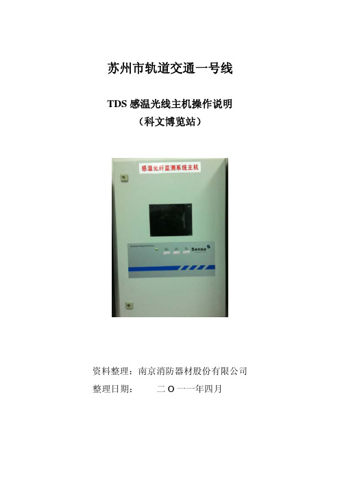
客户支持 为了使我们所有的用户,都可享受产品的支持和服务,当你需要更多的信息
或支持,请拨打华魏公司技术服务电话:+8621 5396 0211,或发送 Email 至华魏 公司邮箱:boomjsb@。为尽快响应你的请求,请附带下述信息:
· 你公司的名字和地址; · 你的电话和传真号码; · 联系人姓名和 E-mail 地址; · 在 DTS 后面板设备铭牌上的 DTS 类型和序列号; · 软件版本号; · 故障描述。
4.1.1 DTS 壁挂式的安装.......................................................................................................... 11 4.1.2 传感光缆的安装 ............................................................................................................ 12 4.2 系统调试 ............................................................................................................................... 14 4.2.1 配置文件设置 ................................................................................................................ 15 4.2.2 软件的操作步骤 ............................................................................................................. 23 第五章 维护和保养 ........................................................................................................................ 25 第六章 注意事项 ............................................................................................................................ 27
传输设备硬件安装操作指导

传输设备硬件安装操作指导1. 概述本文档旨在提供有关传输设备硬件安装的操作指导。
在进行任何硬件安装操作之前,请确保您已经阅读并理解了设备的安全说明和操作手册。
2. 硬件准备在开始安装传输设备之前,您需要根据设备的规格和要求准备以下硬件:2.1 主机设备•一台适用于传输设备的电脑或服务器。
•必要的接口和插槽,如PCIe插槽或USB接口。
2.2 传输设备•传输设备主体。
•配套的电源适配器。
•所需的数据线缆,如SATA数据线缆或USB线缆。
•其他必要的附件,如安装支架或固定螺丝。
3. 安装步骤请按照以下步骤操作以完成传输设备的安装:3.1 准备工作在开始安装之前,请先关闭主机设备,并断开与电源的连接。
确保您处于一个无尘、无静电的工作环境中,以防止对设备造成静电击穿或其他损坏。
3.2 连接传输设备根据传输设备的接口类型,选择相应的数据线缆,并将其连接到传输设备和主机设备之间的接口上。
确保连接牢固,握紧相关接口的螺丝。
3.3 安装传输设备根据传输设备的安装方式,选择合适的安装支架或固定螺丝,并将传输设备安装到主机设备的相应插槽或位置上。
确保传输设备与主机设备接触良好,并且稳固固定。
3.4 连接电源将传输设备的电源适配器插头连接到设备的电源接口上。
然后,将适配器的另一端插入电源插座。
确保该连接牢固,电源供电正常。
3.5 检查和测试完成安装后,重新连接主机设备的电源,并开机进行检查和测试。
确保传输设备被主机设备正常识别,并且可以在操作系统中被访问和使用。
如果设备无法正常工作,建议检查连接和安装步骤是否正确,并参考设备的相关文档进行故障排除。
4. 安全注意事项在硬件安装过程中,请注意以下安全事项:•确保设备和主机都处于关机状态,并断开与电源的连接。
•使用适当的工具和附件,确保设备的稳固安装。
•小心处理数据线缆和电源适配器,避免扭曲或损坏。
•阅读并理解传输设备的安全说明和操作手册,确保正确操作。
5. 总结本文档提供了传输设备硬件安装的操作指导。
杰尼奥电子D5000系列数字无线麦克风系统说明书

D5000 Series Digital Wireless Microphone SystemCOOKBOOKHeadset microphone WH-4000H WH-4000ATie-clip microphone YP-M5300YP-M5310Wireless antenna YW-4500Antenna distributor WD-5800Digital wireless transmitter WM-D5300 (belt-pack type)Digital wireless microphone WM-D5200 (handheld type)Battery charger BC-2000Rechargeable battery WB-2000-2SpeakerAmplifierDigital wireless receiverWT -D5800IndexSystem Equipment ConfigurationSystem Equipment Configuration How the Digital Wireless System Works Advantages of the Digital Wireless System Installation/Setting Procedures – One Room Installation/Setting Procedures – Multiple Rooms Installation of the YW-4500 Wireless Antenna Antenna Distribution Frequency T ableProcedure for Reusing the Same Frequency Encryption Function Settings Interference Countermeasures Antenna Attenuator FBS Setting EQ SettingOptimizing Sound Volume...1...2...3, 4...5...6...7...8, 9...10, 11, 12, 13...14, 15...16...17...18...19...20 (21)*BC-2000 and WB-2000-2 are not designed for the use in the U.S. and Canada, and available in these countries.**How the Digital Wireless System WorksSignal waveforms are used to represent sound, and the state of the sound is expressed according to the width or height of the waveform. Wireless microphones transduce the waveform of audio entering the microphone into an electrical signal and transmit that signal to a tuner over radio waves. In this event, it is an analog wireless system that processes the audio signal as it is in the waveform. On the other hand, it is a digital wireless system that digitally processes the audio signal.More specifically, in the digital system, after an analog signal (waveform) is transduced into a digital signal (asignal simplified by binary numbers 0 and 1) and transmitted by radio, the digital signal is demodulated into an analog signal and then the audio is output. By digitally processing and simplifying the audioinformation to be transmitted, the system can have a variety of advantages, including strong immunity to noise and maintenance of clear sound.Let’s have a look at the “D/U ratio” of analog-to-digital wireless systems. The D/U ratio refers to the ratio of the desired (D) signal to the undesired (U) signal (unit: dB). The desired signal represents the level of that signal, while the undesired signal represents the level of signal interference, otherwise called noise. The D/U ratio decreases as the undesired signal increases. The D/U ratio can be considered to be a value necessary to maintaining clear sound in a wireless system. If a comparison is made of the necessary D/U ratio between analog and digital wireless systems, it is 40dB for analog systems and 20dB for digital systems. From this, it can be seen that the digital wireless system has an edge over the analog wireless system by 20dB in terms of necessary D/U ratio, indicating that the digital system can maintain clear sound in circumstances where a lot of undesired signals are present.» How the Digital Wireless System Works» Why are digital wireless systems resistant to interference signals?Analog System Digital SystemDigital signal processing of analog audioDemodulation of digital to audible analog signal(analog)“H el l o ”Audio (analog)12Wireless receiverBroadcast122Not only can the digital wireless system reduce the influence of noise, it can also maintain clear sound quality by means of digital processing. In addition to this, there are various advantages unique to the digital wireless system.» Use of Multiple Channels in the Same AreaSince the wireless microphone makes itself a source of noise, when using multiple channels in the same area, channels must be arranged to avoid radio interference due to intermodulation interference. In the case of the analog wireless system, the most efficient channel arrangement is as shown in the [Analog] figure below if the intermodulation interference of radio waves is taken into consideration. In this arrangement, the simultaneous use of 6 channels is all it can handle per 4 MHz band.* This is an example.In the digital wireless system, however, since one of its features is being immune to the influence of noise, even when the intermodulation interference occurs, individual channels are less likely to be affected by it. As a result, equal-interval channel arrangements such as shown in the [Digital] figure below becomes possible, allowing up to 10 channels to be used simultaneously per 4 MHz band.* This is an example.» Interference Noise MutingAnalog systems are prone to generation of strange noises when exposed to radio interference. Conversely, radio interference is muted in digital systems, so strange noises are not produced.» Reuse of the Same ChannelAnother advantage of the digital wireless system is that simultaneous use of multiple microphones on the same frequency in the same area can be realized more easily because of its immunity to radio interference and noise.In the case of analog systems, the distance between microphones should be at least 100 meters when using the same frequency channel in the same area to ensure 40 dB of D/U ratio. However, in the case of digital systems, the distance can be reduced to 30 - 40 m*, making it easier to cope with even a building (area) with multiple rooms that require multiple microphones.*This can change depending on antenna mounting conditions or room conditions, such as the thickness or material of walls.Area and RoomRoomRoom» Improved SecurityConventional analog wireless systems transmit their audio signals through FM modulation. With this method, it is possible that communications could be intercepted by general broadband receivers (FM radio, etc.), causing much anxiety in terms of security. On the other hand, with digital systems, since the audio is transmitted through digital modulation, only noise can be heard if received by a broadband receiver. This can prevent exposure of information, leading to improvements in the security of information communication.(Horizontal coverage of antennas, Page 7)the supplied antenna.the supplied antenna.(Installation of the YW-4500 Wireless antenna, Page 7)o Step (3)(Antenna distribution, Page 8, 9)1) Select an arbitrary bank from Banks 1 – 4 at the receiver. (Frequency table, Page 10 -13) If you need more simultaneously usable channels, then use Bank A – F . In this case, please switch transmitter's T ransmission Output to "L (1mW)".* Banks A – F cannot be used when including existing analog wireless equipment in the system. 2) Check for idle channels using the channel scanning function.3) Similarly, perform bank settings and idle channel assignments for the remaining receivers.4) Set the transmitters for the same bank and frequency channels as the receivers.Perform encryption settings if it is necessary to prevent eavesdropping.(Encryption settings, Page 16)(Radio interference countermeasures, Page 17)(FBS settings, Page 19)(EQ Settings, Page 20)(7) Optimize the sound volume.(Sensitivity and volume settings, Page 21)Installation/Setting Procedures - One Room(1) Determine the operation range. (Horizontal coverage of antennas, Page 7)the supplied antenna. Use the supplied antenna.the supplied antenna. Use the YW-4500 external antenna.(Installation of the YW-4500 Wireless antenna, Page 7) (2) Determine the number of transmitters to use.o Step (3)(Antenna distribution, Page 8, 9)(3) Confirm the number of channels that can be simultaneouslyused by the frequency table. (Frequency table, Page 10 - 13)Page 14,15)1) Select an arbitrary bank from Banks 1 – 4 at the receiver. (Frequency table, Page 10 - 13)If you need more simultaneously usable channels, then use Bank A – F.In this case, please switch transmitter's T ransmission Output to "L (1mW)".* Banks A – F cannot be used when including existing analog wireless equipment in the system.2) Check for idle channels using the channel scanning function.3) Similarly, perform bank settings and idle channel assignments for the remaining receivers.4) Set the transmitters for the same bank and frequency channels as the receivers.Perform encryption settings if it is necessary to prevent eavesdropping. (Encryption settings, Page 16)(Radio interference countermeasures, Page 17)(8) Optimi sound quality.(FBS settings, Page 19)(EQ Settings, Page 20)(Sensitivity and volume settings, Page 21) Installation/Setting Procedures - Multiple RoomsPoint 1Mount the two antennas within 20 – 30m (outdoor applications: 40 – 50m) visible range from the microphone’s area of intended use.Both antennas should be within visible range from any location where the microphones are to be used. This is necessary for ensuring optimal conditions for one antenna to receive signals when the microphone my experience the other antenna's dead spot. In other words, the shape of the room does not matter provided that the above conditions are met. On a diagram of the site, use a compass to draw two circles representing a radius of 20 – 30m with each antenna as the central point. If usage locations fall within either of the two circles, such locations can be deemed to be okay.Point 2As a guideline, the distance between the two antennas should be 3 – 18m. Although the coverage area becomes wider as the distance between antennas increases, this degrades the diversity effect, and signal interruption will become more liable to occur.If possible, locate one antenna in the direction that can be viewed from the position where the microphone is held, and the other antenna in the opposite direction (behind the microphone holder).Point 3In indoor installations, as a general guideline, install antennas at a height of 2 – 4m above the floor, lest the signal be blocked by people in the room. Keep the antennas about 30cm below the ceiling. Install the antennas so they face in the specified directions. When making protectors, use resin or timber and do not use metallic materials.• Avoid positioning antennas close to metallic objects wherever possible.• Avoid mounting antennas inside a ceiling or wall.• Select locations where the antenna can be protected from being hit and damaged by objects.• Protect the antennas against rain water.Important points for selecting the mounting position of diversity antennas are as follows:Horizontal coverage of antennas under optimal conditionsInstallation of the YW-4500 Wireless Antenna• YW-4500• WT -D5800 Rod Antenna• Using 1 - 3 channelsAntennas can be distributed without using the WD-5800 Antenna Distributor.• Simultaneous use of 4 channels• Simultaneous use of 5 – 8 channelsaudio• Simultaneous use of 9 -16 channels• Simultaneous use of 17 - 32 channelsaudioto mixeraudioto mixeraudioto mixeraudioto mixeraudioto mixeraudioto mixeraudioto mixeraudioto mixeraudioto mixeraudioto mixeraudioto mixeraudioto mixerSplit antennas into two systems and construct a system of up to 32 channels.• Frequency table which can be used with 5000 Series analog wireless systemCompatible Frequency List*WM-D5200/D5300, WT-D5800: BANK 1 - 4WM-4200/4300/5220/5270/5320/5225/5265/5325: BANK 1– 4WT-4800/5800/5805: BANK 1– 4WM-4210/4220/4310, WT-4810/5100/5810, WTU-4800: BANK 1• When needing more channels*Banks A - F cannot be used when including existing analog wireless equipment in the system.Compatible Frequency List*WM-D5200/D5300, WT-D5800• Frequency table which can be used with 5000 Series analog wireless systemCompatible Frequency List*WM-D5200/D5300, WT-D5800: BANK 1 - 4WM-4200/4300/5220/5270/5320/5225/5265/5325: BANK 1– 4WT-4800/5800/5805: BANK 1– 4WM-4210/4220/4310, WT-4810/5100/5810, WTU-4800: BANK 1• When needing more channels*Banks A - F cannot be used when including existing analog wireless equipment in the system.*WM-D5200/D5300, WT-D5800• Frequency table which can be used with 5000 Series analog wireless system*WM-D5200/D5300, WT-D5800: BANK 1 - 4WM-4200/4300/5220/5270/5320/5225/5265/5325: BANK 1– 4WT-4800/5800/5805: BANK 1– 4WM-4210/4220/4310, WT-4810/5100/5810, WTU-4800: BANK 1• When needing more channels*Banks A - E cannot be used when including existing analog wireless equipment in the system.*WM-D5200/D5300, WT-D5800• Frequency table which can be used with 5000 Series analog wireless system*WM-D5200/D5300, WT-D5800: BANK 1 - 4WM-4200/4300/5220/5270/5320/5225/5265/5325: BANK 1– 4WT-4800/5800/5805: BANK 1– 4WM-4210/4220/4310, WT-4810/5100/5810, WTU-4800: BANK 1• When needing more channels*Banks A - E cannot be used when including existing analog wireless equipment in the system.*WM-D5200/D5300, WT-D5800When using transmitters in numbers greater than the number of simultaneously usable channels and in close proximity to each other, microphones operating on the same frequency can be used simultaneously by utilizing their digital characteristics. Note, however, that the same frequency cannot be used in the same room.1. Make channel plans1) Referring to the Frequency T able, select an arbitrary bank from A to F . 2) Scan receiver channels.• C band: Searches for channels in two banks including the currently-set bank and displays idle channels.Combinations of scanned banks are as follows: When Bank A or B is currently set a Searches for and displays idle channels in Banks A and B. When Bank C or D is currently set a Searches for and displays idle channels in Banks C and D.When Bank E or F is currently set a Searches for and displays idle channels in Banks E and F .• G band: Searches for all bank channels in the dedicated digital plan, and displays idle channels.3) Assign idle channels to multiple rooms as shown in the following examples to prevent channelsoperating on the same frequency from being too close to each other.[Example] Same floor or same location on each floor.[Example] Multiple rooms are adjacent to each other on both upper and lower floors in facilities like rental conference rooms and schools. There is a high possibility that the frequencies being used in the ‐ Keep channels using the same frequency as far away from each other as possible. If used on the same floor, keep them at least two rooms apart.‐ Set the wireless microphone’s transmission output to “L.”‐ Adjust the antenna attenuator.2. Use "Code" (recommended)This function prevents interference between channels sharing the same frequency. By performing Code settings, receivers and transmitters can be paired, muting radio signals on the same frequency that may exist in the surrounding area. Code setting is effective when the encryption function is not set.» Code setting proceduresFigure a. Even if the code is the same, if the power for both microphones is ON, radio interference will not occur. (Since the stronger radio signal takes precedence, only the microphone within the immediate area is reproduced.)Figure b. If power to either area is turned off when Figure a conditions exist, Receiver 1 may mistakenly receive MIC 2 audio. (Since the code is the same, it would be impossible to distinguish between MIC 1 and MIC 2.)Figure c. If different codes are set in Area 1 and Area 2, mistakenreception will not occur even if power to the microphone for either area is turned off. (Since microphones in both areas differ in code, audio is muted.)Code settingssolve these problems.Hold down the “SET” key for 2 seconds or more.Select “CODE” and press “SET”Select an arbitrary numberSet the same code for the transmitter to be paired.WT -D5800M E N U >C O D ES E T C O D ENOTE: Since the encryption function, which enhances security, also requires pairing of a transmitter with a receiver, code setting is unnecessary if the encryption function is used.Hold down the “SET” key for 2 seconds or more.Select ENCRYPTION from the menu Select “ON”Select P AIRING from the menu1) Enable receiver’s encryption function.2) Pair the receiver with a transmitter.Switch on the transmitter while holding down the “Encryption” setting switch.Press and hold “SET” till the “SUCCESS” is displayed.If encryption function is achieved, the“ANT A/B” indication and the lock icon lights red.If pairing is achieved, the “ANT A/B” indication lights green andthe transmitter’s “Encryption” light also lights.WT -D5800SETM E N U>H O L D T H E S E T K E YM E N U >PA I R I N GPA I RI N G P RO C E S S R E C E I V I N GPA I R I N G P RO C E S S S U C C E SSEncryption Function SettingsExposure of important information can be prevented by pairing a receiver with a transmitter by TOA’s proprietary security IDs.» Engryption setting proceduresInterference Countermeasures Order of Actions (Action Flowchart)Antenna Attenuator» Antenna Attenuator FunctionThis function decreases the antenna reception sensitivity so as to minimize reception of distant interference radio signals.•When to use this functionUse this function when radio interference or signal interruption caused by the interference of other systems intermittently occurs.Note: Since the use of an attenuator shortens the transmission distance and reduces the range of the usable area, ensure that the microphone can be used without signal interruption in the intended usage area after performing settings.The attenuator can effectively reduce interference signals if they are relatively weak. The most effective results may not be obtained when interference signals are strong (i.e. when audio interference constantly occurs).•Proper use of two attenuatorsUse either the WT -D5800 or YW-4500 attenuator to attenuate the reception sensitivity by 10dB. The WT -D5800 may be more convenient as it allows settings by hand.Since the attenuation of both the YW-4500 and WT-D5800 attenuators are added together, when wishing to attenuate reception sensitivity by at least 10dB, use both attenuators in combination.(This is a rare case, though.)UndesiredUndesiredFBS SettingIt is a function that the built-in feedback suppressor filter automatically works to suppress acoustic feedback when the feedback occurs.Use this function when increases in the receiving wireless microphone’s sound volume tend to generate acoustic feedback and reduce speech clarity or make it impossible to achieve the necessary sound volume for broadcast.» What is the feedback suppressor function?» What is the FBS built into the WT -D5800?NOTE: Acoustic feedback, or howling, is generated when sound output from a speaker reenters the microphone. Before using this function, check to see if the microphone and speaker are positioned too close to each other, or if the sound volume is louder than necessary.In circumstances where feedback is especially liable to occur, the most effective results may not be obtainable, or sound quality may vary greatly.LevelFeedback suppressor filterFrequencyFeedback frequencyHold down the “SET” key for 2 seconds or more.Select “FBS” and press “SET”WT -D5800M E N U >F B SS E T F B S 3O NEQ Setting (Recommended)This function optimizes audio characteristics for each model of handheld wireless microphone or any microphone connected to the belt-pack transmitter.Select the model number of the microphone to use, and perform settings in EQ setting mode.» What is the microphone EQ built into the WT -D5800?NOTE: This function is set to OFF by default.Set the “Microphone EQ” to OFF when the corresponding model number is not shown in the display of the EQ setting mode.Hold down the “SET” key for 2 seconds or more.OptionsWT-D5800S E T E Q P R E S E T 3E X I TS E T E Q P R E S E T 3Y P -M 5300S E T E Q P R E S E T 3W M -D 5200S E T E Q P R E S E T 3O F FS E T E Q P R E S E T 3Y P -M 5310S E T E Q P R E S E T 3W H -4000AS E T E Q P R E S E T 3W H -4000HM E N U>E Q P R E S E TOptimizing Sound Volume(1) Set the receiver’s volume control to the 2 o’clock position.For current TOA wireless receivers with the volume control located on the front panel, the 2 o’clock position (scale 7) is the volume control position that minimizes sound distortion until the maximum input sound pressure is applied to the microphone. From that position to the maximum volume position, a gain of approximately 10dB is made available as an allowance when turning up the volume.(2) Set the transmitter’s (microphone’s) sensitivity to “H” or “L ” depending on whether the volume is insufficient or noise is detected at normal sound volume, or if distortion is not noticeable when speaking in a loud voice.n to the maximum volume position, a gain of approximately 10dB is made available as an allowance when turning up the volume.(3) Adjust the input level of the amplifier or mixer to an appropriate sound volume for use under normal conditions.Microphone sensitivity can be set to "0 dB (H)" or "-10 dB (L)".TOA Corporationwww.toa.jp。
安装DTS的方法

DTS-HD Srteamplayer下载安装使用办法随着高清音乐的普及,无损音乐越来越多,普通的MP3也满足不了大家听觉上的需要,现在网络上流行的无损音乐有FLAC、APE等,但对于一些追求高品质发烧的朋友来说,这是远远不够的,传统的2.1声道已经被DTS-5.1环绕多声道为基础的效果占领,随着追求的更高,目前已出来的DTS6.1-7.1也在逐渐着走进人们的耳朵,这是一场听觉上的革命。
就像DVD将VCD淘汰,HD(蓝光)将DVD淘汰一样。
那么,如何在电脑上播放DTS环绕多声道音乐呢?有些网友可能会尝试过,在电脑上播放都有嘶嘶声,就像极大的电流声,其实,这是解码的问题。
而且,不用5.1音箱,2.1的普通音箱我们也可以通过几款软件达到试听的效果。
目前,网络上流行的播放软件有几款,Foobar2000(需要dts解码插件,效果不够细腻),暴风影音(效果很差),poowerDVD(兼容显示很差),WinDVD(很一般).千千静听(一般)。
需要介绍的是DTS官方播放器→DTS-HD Srteamplayer,不得不说,播放效果极其震撼,听过之后就不得不放弃其它软件,只可惜,由于这播放器是英文版,虽然中国汉化高手极多,但始终未见出来一个汉化版,幸运的是操作很简单。
在这里,小勾收集整理了网上资料为大家说一下DTS-HD Streamplayer的安装办法及使用办法。
下载地址回复本帖后可见,经卡巴与360杀毒显示安全(最新病毒库2010.11.15)一、安装步骤1、如果你是普通板载声卡(即主板自带声卡-集成声卡非外载),要预先安装ASIO4ALL,以实现ASIO输出。
压缩包内ASIO4ALL_2_9_SCN是中文版,ASIO4ALL_2_10_beta1_English.exe是目前最新版。
2、ASIO4ALL安装后请将ASIO的缓冲区大小调到最大采样点(看压缩包内图→ASIO4ALL设置),否则有可能播放不流畅。
linx60604电网定制安装手册-d5000用户-20150612

Rocky6.0.60.4定制安装手册1.通过安装光盘或U 盘启动凝思科技公司出品的linx6.0.60.4系统,如图1所示。
图 1: 安装光盘的启动画面2.选择“Advanced options”菜单项并回车,如图2所示。
图 2: 出现电网定制自动安装的画面3.选择“State Grid automated install”菜单项并回车,如图3所示,建议在安装过程中创建1个普通用户,以便于使用凝思资源控制器对该用户进行管理。
输入一个普通用户名,如:d5000或ems或oms或kingbase或df8003等。
图 3: 输入一个普通用户名的画面4.按tab键切换到“Continue”按钮回车,如图4所示,输入图3中的普通用户名对应的家目录,在d5000项目中,一般为/home/d5000/单位名的汉语拼音。
如:/home/d5000/guodiao,/home/d5000/zhejiang,/users/ems,/users/oms,/home/kingsoft等。
图 4: 指定普通用户名家目录画面5.按tab键切换到“Continue”按钮回车,如图5所示,输入图3中的普通用户名对应的shell,d5000项目中d5000用户的shell都是指定为“tcsh”,其他用户根据情况指定,如:bash或tcsh。
图 5: 指定普通用户使用的shell画面6.按tab键切换到“Continue”按钮回车,如图6所示。
建议给硬盘至少分配5个分区,1个交换分区swap(8GB大小),1个根分区(硬盘大小的15%),1个挂载到/var目录的分区(硬盘大小的25%),1个挂载到普通用户家目录的分区(硬盘大小的35%),1个挂载到普通用户家目录下的var子目录的分区(硬盘大小的25%)。
上面的分区只是建议,不是必须的。
但必须分区2个分区,1个swap分区(8GB大小),1个根分区。
图 6: 指定磁盘分区画面7.按tab键切换到需要分区的硬盘指示行上回车,如图7所示。
厂站监控数据接入D5000系统讲解

厂站监控 数据接入
高软功能 平台功能 应用 应用 系统跨越性 2016-2017年,面临智能电网调度控制系统全新换代,从 iES600 安全边界 地县互联 的转换为D5000 系统,各项工作都需要定制专门的实施方案。系统建设前期,厂站监控 配置 调试 数据接入工作尤为重要,直接影响到后续工作的准确高效开展,因此选定厂站监控数据
主站配置
网络通道一
网络通道二
地址一:37.129.11.4 地址二:37.129.11.132 地址一:37.129.11.5 地址二:37.129.11.133
厂站监控数据接入D5000系统
厂站接入典型案例 厂站接入典型案例
完美
难以实现
厂站监控数据接入D5000系统
厂站接入典型案例 厂站接入典型案例
双主模式
主调链路
厂站监控数据接入D5000系统
备调链路
厂站接入特殊案例 厂站接入特殊案例
04
主 备 调 不 同
主调 第一套总控的端口1连接第一套数据网 第二套总控的端口2连接第二套数据网 备调 第一套总控的端口2连接第一套数据网
第二套总控的端口1连接第二套数据网
主备模式
主调链路
厂站监控数据接入D5000系统
备调链路
厂站接入特殊案例 厂站接入特殊案例
05
主 备 调 相 同
主调 第一套总控的端口1连接第一套数据网 第二套总控的端口2连接第二套数据网 备调 第一套总控的端口1连接第一套数据网 第二套总控的端口2连接第二套数据网
主备模式
主调链路
厂站监控数据接入D5000系统
备调链路
应用效果 总结展望
未知 问题
精益求精
请您指正
THANKS
- 1、下载文档前请自行甄别文档内容的完整性,平台不提供额外的编辑、内容补充、找答案等附加服务。
- 2、"仅部分预览"的文档,不可在线预览部分如存在完整性等问题,可反馈申请退款(可完整预览的文档不适用该条件!)。
- 3、如文档侵犯您的权益,请联系客服反馈,我们会尽快为您处理(人工客服工作时间:9:00-18:30)。
智能电网调度技术支持系统
安装手册
调度员培训模拟(DTS)
北京科东电力控制系统有限责任公司
2010年08月
目录
关键词 (2)
摘要 (2)
1引言 (3)
1.1 目的 (3)
1.2 参考资料 (3)
1.3 术语和缩写词 (3)
2 操作系统安装 (4)
3 数据库安装 (4)
4 第三方软件安装 (4)
5 基础平台安装 (4)
5.1 准备工作 (4)
5.2 安装步骤 (4)
5.3 系统配置 (4)
5.4 验证与测试 (5)
6 调度员培训模拟(DTS)应用安装 (5)
6.1 准备工作 (5)
6.2 安装步骤 (5)
6.3 系统配置 (5)
6.4 验证与测试 (5)
关键词
平台安装、应用服务、DTS安装、人机安装。
摘要
本手册面向项目实施人员、系统维护人员介绍DTS的安装步骤与方法说明,主要包括对平台安装的要求、人机安装及DTS应用的安装说明。
1引言
1.1 目的
本手册面向项目实施人员、系统维护人员说明DTS的安装步骤与方法。
1.2 参考资料
本手册编写参考了以下智能电网调度技术支持系统相关规范与手册:
●SG-OSS-PAC-OG-v1.0-调度员培训模拟(DTS)-v1.0
●SG-OSS-PAC-UHB-v1.0-调度员培训模拟(DTS)-v1.0
●SG-OSS-PAC-技术手册-调度员培训模拟(DTS)-v1.0
●SG-OSS-PC-PHB-FP-v1.0-调度员培训模拟(DTS)程序员手册-v1.0
●(530-1)调度员培训模拟(DTS)应用功能规范
●(530-1.2)调度员培训模拟(DTS)应用详细设计
1.3 术语和缩写词
1)调度员培训模拟DTS Dispatcher Training Simulator
调度员培训模拟是一套数字仿真系统,它运用计算机技术,通过建立实际电力系统的数学模型,再现各种调度操作和故障后的系统工况,并将这些信息送到电力系统控制中心的模型内,为调度员提供一个逼真的培训环境,以达到既不影响实际电力系统的运行而又使调度员得到身临其境的实战演练的目的。
DTS是电网培训和研究分析的最佳工具。
2)教员台
教员使用的硬件和软件环境的总称, 包括教员对培训过程进行监视、控制和评价功能的软件模块。
3)学员台
学员使用的硬件和软件环境的总称,应尽可能与实际的控制中心环境一致。
2操作系统安装
与基础平台与应用部分操作系统安装方法一致。
DTS系统部署在安全II区,需要注意相关的网络配置及IP设置。
3数据库安装
安装步骤和方法与基础平台与应用部分一致。
DTS系统部署在安全II区,需要注意相关的防火墙打开数据库服务相关的端口。
验证方法:使用数据库客户端可以查询公共模型表。
4第三方软件安装
安装步骤和方法与基础平台与应用部分一致,无特殊第三方软件安装需要。
在进行联合反事故演习时,需要远程用户,从DTS的Web门户网页下载相应的Java 版本,并进行系统默认步骤安装即可。
5基础平台安装
5.1 准备工作
见基础平台相关安装手册。
5.2 安装步骤
见基础平台相关安装手册。
5.3 系统配置
●将DTS配置成系统中独立的子系统;
●。