turtlebot硬件安装手册
杰尼霍夫电子产品安装指南说明书

IMPORTANT SAFETY INSTRUCTIONSPLEASE READ ENTIRE MANUAL PRIOR TO USE – SAVE THESE INSTRUCTIONSCAUTION: Avoid potential personal injuries and property damage!●Please read through these instructions completely to be sure you’re comfortable with this easy install process. ●Do not use this product for any purpose not explicitly specified by manufacturer.●Manufacturer is not responsible for damage or injury caused by incorrect assembly or use.●If you do not understand these instructions or have doubts about the safety of the installation, assembly or use of this product, contact Customer ServiceThis product conforms to and should be properly grounded in compliance with requirements of the current National Electrical Code or codes administered by local authorities.All electrical products may present a possible shock or fire hazard if improperly installed or used. This product may bear the mark of a Nationally Recognized Testing Laboratory and should be installed in conformance with current local and/or the National Electrical Code.Legrand AV Inc. and its affiliated corporations and subsidiaries (collectively, “Legrand”), intend to make this manual accurate and complete. However, Legrand makes no claim that the information contained herein covers all details, conditions, or variations. Nor does it provide for every possible contingency in connection with the installation or use of this product. The information contained in this document is subject to change without notice or obligation of any kind. Legrand makes no representation of warranty, expressed or implied, regarding the information contained herein. Legrand assumes no responsibility for accuracy, completeness or sufficiency of the information contained in this document.©2020 Legrand AV Inc. All rights reserved. SANUS is a Legrand brand. SANUS and the SANUS logo are trademarks of Legrand.Legrand AV INC. 6436 City West Parkway; Eden Prairie, MN 55344 USA1025682 03/20Before getting started, let’s make sure this product is perfect for you!Replace Trim Plate。
uit bl2000sv1200硬件安装维护指南.doc

2. 键盘操作约定
格式 <键 1+键 2>
意义 表示在键盘上同时按下几个键。如<Ctrl+Alt+A>表示同时按 下“Ctrl”、“Alt”、“A”这三个键
BL2000 硬件安装维护指南
<键 1,键 2>
表示先按第一键,释放,再按第二键。如<Alt,F>表示先 按<Alt>键,释放后,紧接着再按<F>键
目录
BL2000 硬件安装维护指南
1-3 1-3 1-3 1-3 1-4
2-1 2-1 2-1 2-1 2-2 2-6
3-1 3-1 3-1 3-2 3-3 3-6 3-9 3-10 3-10 3-11 3-11
4-1 4-1 4-1 4-2 4-5 4-7
-i-
4.6 电源模块维护 4.7 散热风扇模块维护 4.8 DOM 卡模块的维护 4.9 IPMI 卡的安装和维护 4.10 信号灯的安装和维护 4.11 硬盘指示灯状态说明
深圳市越疆科技有限公司 Dobot 视觉套件安装指南说明书

Dobot视觉套件安装指南文档版本:V1.0发布日期:2018-09-12深圳市越疆科技有限公司版权所有©越疆科技有限公司2019。
保留一切权利。
非经本公司书面许可,任何单位和个人不得擅自摘抄、复制本文档内容的部分或全部,并不得以任何形式传播。
免责申明在法律允许的最大范围内,本手册所描述的产品(含其硬件、软件、固件等)均“按照现状”提供,可能存在瑕疵、错误或故障,越疆不提供任何形式的明示或默示保证,包括但不限于适销性、质量满意度、适合特定目的、不侵犯第三方权利等保证;亦不对使用本手册或使用本公司产品导致的任何特殊、附带、偶然或间接的损害进行赔偿。
在使用本产品前详细阅读本使用手册及网上发布的相关技术文档并了解相关信息,确保在充分了解机器人及其相关知识的前提下使用机械臂。
越疆建议您在专业人员的指导下使用本手册。
该手册所包含的所有安全方面的信息都不得视为Dobot的保证,即便遵循本手册及相关说明,使用过程中造成的危害或损失依然有可能发生。
本产品的使用者有责任确保遵循相关国家的切实可行的法律法规,确保在越疆机械臂的使用中不存在任何重大危险。
越疆科技有限公司地址:深圳市南山区留仙大道3370号南山智园崇文区2号楼9-10楼网址:/目的本手册介绍了Dobot视觉套件说明和安装指南,方便用户了解和使用。
读者对象本手册适用于:•客户工程师•销售工程师•安装调测工程师•技术支持工程师修订记录符号约定在本手册中可能出现下列标志,它们所代表的含义如下。
危险警告注意说明1. 视觉套件说明 (1)概述 (1)1.2视觉套件清单 (1)1.3相机参数说明 (1)1.4光源参数说明 (2)1.5相机镜头参数 (3)2. 安装指南 (4)安装相机 (4)安装Dobot Magician (13)安装Dobot M1 (13)1. 视觉套件说明概述图像处理系统通过设置图像(视觉套件获取)的色度(Hue)、饱和度(Saturation)、亮度(V alue)、特征大小来提取图像的特征,并把图像坐标转换成机械臂坐标传送给机械臂,利用机械臂完成智能分拣。
D系列川崎机器人 安装连接手册.
4.1使用吊车..................................................................14
4.2使用叉车..................................................................15
本手册只说明了控制单元的安装与连接、接线及其初级电源(主电源。机器人手臂的相关信息请参阅下列手册。
“安装和连接手册=机器人手臂=”
1.本手册并不构成对使用机器人的整个应用系统的担保。因此,川崎公司将不会对使用这样的系统而可能导致的事故、损害和(或与工业产权相关的问题承担责任。
2.川崎公司郑重建议:所有参与机器人操作、示教、维护、维修、点检的人员,预先参加川崎公司准备的培训课程。
3.无灰尘、烟雾、水、油等。(控制箱保护等级:IP53
(除主空气开关的把手、变压器和散热片部分外。见下图。
4.无易燃、腐蚀性液体和气体。
5.无有过大的振动。
6.无电气干扰。
(控制箱初级电源电气噪声:小于1KV/1μs
7.电源供电电压在规定范围内。(变化在+/-10 %以内
8.具备专用接地线。(100 Ω以下
9.安装位置位于机器人(带手爪或射枪的运动范围外(至少1 m、安全围栏的外边。
也需满足下列条件:
具备足够空间,以便在维修时进入控制箱。
安全围栏上,安装带有安全插销的进口。
关于安全围栏的技术细节,请参考对各区域的具体要求。
(例如EN953、EN294、EN811、EN1088、ISO13852、ISO13854和ISO/NP14120
Bosch安装手册说明书

7. 将固定环和垫圈 (下图中的项目 2)连接到表面底座分线盒。 AutoDome Easy II 室外摄像机随附了这些组件。确保固定环带 有埋头螺纹孔的一侧朝向您。
图 4.6 室外安装场合中的 O 型圈和固定环放置
1 M3 – 0.5 x 6 十字平头螺丝 (随 AutoDome Easy II 室外摄像机一起提供)
9. 将 1/2 英寸 (15 毫米)NPS 接头安装到选定的导线孔。确保防 水接头可以为本设备保持 IP 环境防护等级。
10. 使用四 (4) 颗用户自备的 M4 或 10 号盘头螺丝将表面底座分线盒 固定到表面上。使用长度至少为 10 毫米 (0.39 英寸)的螺丝。 注:对于室外安装,请确保将四 (4) 个内径 3.97 毫米 X Ø1.78 毫米的 O 型圈拧到四 (4) 颗 M4 或 10 号盘头螺丝 (用户自备) 上。参见 第 5 步。
AutoDome Easy II
重要安全说明 | zh 5
1
重要安全说明
阅读、遵循并保留以下所有安全文明。 开始操作之前,留意设备上和 操作说明书中的所有警告信息。 1. 只能使用干软布清洁。请勿使用液体清洁剂或喷雾清洁剂。 2. 不要在靠近热源的地方安装设备,例如散热器、加热器、火炉或
其它生热设备 (包括放大器)。 3. 不要阻塞任何通风孔。 4. 不要在靠近水源的地方使用设备,勿让设备被水打湿或暴露在潮
注释 现代 CCD 摄像机中的图像感应器是一个高度精密的元件,需要小心 处理以保证正常的性能和更长的使用寿命。 请遵循有关使摄像机发挥 最佳性能的原则: - 无论摄像机处于工作状态还是存放状态,都不要让感应器暴露在
阳光直射或明亮的聚光灯下。 - 避免强光进入摄像机的视场。强光会导致 “ 拖影 ” 效应,造成在
Turtlebot3+ubuntu20.04+ROSnoetic环境搭建
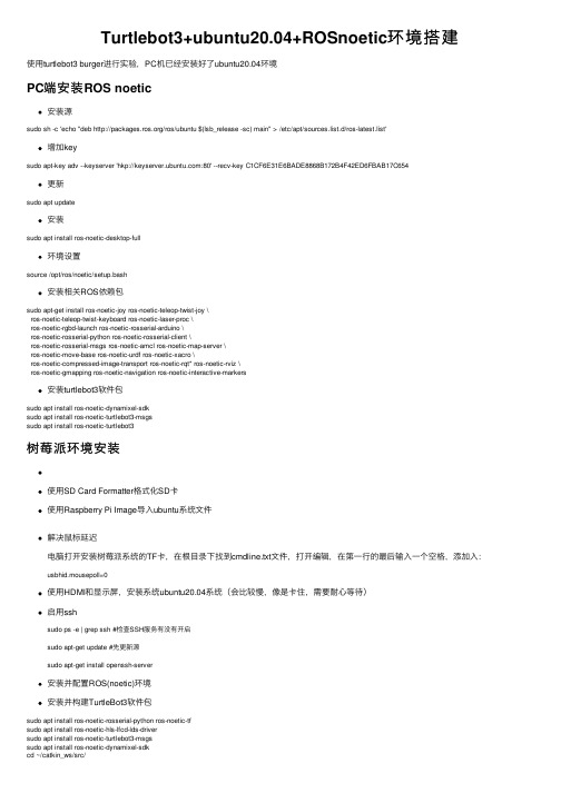
Turtlebot3+ubuntu20.04+ROSnoetic环境搭建使⽤turtlebot3 burger进⾏实验,PC机已经安装好了ubuntu20.04环境PC端安装ROS noetic安装源sudo sh -c 'echo "deb /ros/ubuntu $(lsb_release -sc) main" > /etc/apt/sources.list.d/ros-latest.list'增加keysudo apt-key adv --keyserver 'hkp://:80' --recv-key C1CF6E31E6BADE8868B172B4F42ED6FBAB17C654更新sudo apt update安装sudo apt install ros-noetic-desktop-full环境设置source /opt/ros/noetic/setup.bash安装相关ROS依赖包sudo apt-get install ros-noetic-joy ros-noetic-teleop-twist-joy \ros-noetic-teleop-twist-keyboard ros-noetic-laser-proc \ros-noetic-rgbd-launch ros-noetic-rosserial-arduino \ros-noetic-rosserial-python ros-noetic-rosserial-client \ros-noetic-rosserial-msgs ros-noetic-amcl ros-noetic-map-server \ros-noetic-move-base ros-noetic-urdf ros-noetic-xacro \ros-noetic-compressed-image-transport ros-noetic-rqt* ros-noetic-rviz \ros-noetic-gmapping ros-noetic-navigation ros-noetic-interactive-markers安装turtlebot3软件包sudo apt install ros-noetic-dynamixel-sdksudo apt install ros-noetic-turtlebot3-msgssudo apt install ros-noetic-turtlebot3树莓派环境安装使⽤SD Card Formatter格式化SD卡使⽤Raspberry Pi Image导⼊ubuntu系统⽂件解决⿏标延迟电脑打开安装树莓派系统的TF卡,在根⽬录下找到cmdline.txt⽂件,打开编辑,在第⼀⾏的最后输⼊⼀个空格,添加⼊:usbhid.mousepoll=0使⽤HDMI和显⽰屏,安装系统ubuntu20.04系统(会⽐较慢,像是卡住,需要耐⼼等待)启⽤sshsudo ps -e | grep ssh #检查SSH服务有没有开启sudo apt-get update #先更新源sudo apt-get install openssh-server安装并配置ROS(noetic)环境安装并构建TurtleBot3软件包sudo apt install ros-noetic-rosserial-python ros-noetic-tfsudo apt install ros-noetic-hls-lfcd-lds-driversudo apt install ros-noetic-turtlebot3-msgssudo apt install ros-noetic-dynamixel-sdkcd ~/catkin_ws/src/git clone -b noetic-devel https:///ROBOTIS-GIT/turtlebot3.gitcd ~/catkin_ws/src/turtlebot3rm -r turtlebot3_description/ turtlebot3_teleop/ turtlebot3_navigation/ turtlebot3_slam/ turtlebot3_example/cd ~/catkin_ws && catkin_make -j1source ~/.bashrc使⽤rosdep安装依赖项sudo apt install python3-rosdep2 ros-noetic-rosbashcd ~/catkin_ws && rosdep update && rosdep install --from-paths src --ignore-src -r -yUSB端⼝设定官⽅⽂档操作rosrun turtlebot3_bringup create_udev_rulescd ~/catkin_ws/src/turtlebot3/turtlebot3_bringupsudo cp ./99-turtlebot3-cdc.rules /etc/udev/rules.d/sudo udevadm control --reload-rulessudo udevadm triggeropenCR设置不进⾏这⼀步,后续rosrun会报checksum error,仍然按照官⽅⽂档进⾏,需要注意的是wget https:///ROBOTIS-GIT/OpenCR-Binaries/raw/master/turtlebot3/ROS1/latest/opencr_update.tar.bz2 在进⾏这⼀步时,会connect refuse,按照⽹上其他改host ip映射也不⾏,于是选择⼿动去下载。
太阳刀X3-2B服务器安装指南说明书

IMPORTANT:The Sun Blade X3-2B was previously named the Sun Blade X6270M3server.The product name change does not indicate any change in system features or functionality.This guide describes the minimum steps you must perform to install your server into a supported chassis and power it on for the first time.For a list of documentation for this server,see “Documentation for This Product”at the end of this document.Front Panel DescriptionFigure Legend Server Front Panel Features1Locate LED (white).Press button to identify server.2Ready to Remove LED (blue).Full power removed.3Service Action Required LED (amber).A fault condition has occurred.4OK/Power LED (green).Modes:•SP booting -fast blink,0.125second on,0.125second off.•Standby power -blink,0.1second on,2.9seconds off.•Host booting -slow blink,0.5second on,0.5second off.•Full power -steady on.5Power button.Press briefly to toggle server between standby and full power.Caution -Pressing the Power button for more than 4seconds when in full power initiates immediate shutdown to standby power.This can cause data loss.6NMI button -for Oracle Service use only.7Serial number label.8Two USB 2.0ports.9Universal connector port (UCP).Used for multi-port (dongle)cable.10-13Hard drives (HDDs)or solid state disks (SSDs).Sun Blade X3-2B (formerly Sun Blade X6270 M3)Getting Started GuideBasic Installation TasksThe following tasks describe the basic installation process for the server.For detailed installation information, see the Sun Blade X3-2B Server Installation Guide.▼Review Safety InformationBefore performing an installation,refer to the Safety and Compliance Guide(online)and the Important Safety Information for Sun Hardware System s(in the system accessory kit).▼Review Supported Hardware and Software and Identify Known IssuesReview the Sun Blade X3-2B Product Notes for information on supported software and hardware and any known issues for the server.▼Install Optional ComponentsOptional server components(for example,DIMMs or hard drives)might be packaged and shipped separately. Install these components prior to installing the server into the system chassis.For component installation procedures,refer to the Sun Blade X3-2B Service Manual.▼Insert the Server Into a Chassis1.Verify that the Sun Blade6000modular system chassis is powered on.2.Make sure that the fans are operating and the OK/Power LED illuminates a steady-on green light.If an amber service LED is illuminated on any chassis components,refer to the Sun Blade X3-2B Service Manual for information on how to identify and correct the faults.3.At the front of the chassis,locate the slot that you want to install the server in and remove the filler panel.To unlock the filler panel,squeeze the release levers on the end of filler panel ejector arm.To eject the filler panel,rotate the lever fully outward.To remove the filler panel,pull it out of the chassis.Caution–Thermal over-temperature.Do not operate the chassis with empty slots for more than60seconds.Always insert a filler panel into an empty slot to reduce the possibility of chassis shutdown.If you are not installing a server into a slot,do not remove the slot filler panel.4.Open both of the server ejector levers,and position the server vertically so that the ejectors are on theright.To unlock the ejector levers,squeeze the lock latches located on the end of the ejector levers.5.Carefully,slide the server into the slot until the server stops(see1).6.To completely seat the server in the chassis,rotate both ejector levers inward until the levers lock intoplace and are flush with the face of the server.(see2).Standby power is applied to the server and the service processor(SP)boots.As the SP boots,the OK/Power LED blinks rapidly(125ms on,125ms off).Note–The SP can take several minutes to boot.7.Verify that the SP has finished booting and that the server has successfully powered-on to standby mode.When the server is in standby mode,the OK/Power LED blinks slowly(0.1second on and2.9seconds off).Note–If the chassis power is insufficient,the server OK/Power LED remains off.For information on troubleshooting LED states,refer to the Sun Blade X3-2B Service Manual.▼Set Up Software and Firmware Using Oracle System AssistantThis is the easiest method for setting up the server.If Oracle System Assistant is included with the server,you can use it to update to the latest available firmware and software,configure key server settings,and install a supported operating system.For more information,refer to the server’s OS-specific installation guide.Note–You can also use Oracle ILOM and Oracle Hardware Management Pack to set up the server.For more information about these tools,or for information about how to use Oracle System Assistant,refer to the Sun Blade X3-2B Administration Guide.1.Install the server in the chassis,see“Insert the Server Into a Chassis”on page2.2.To access Oracle System Assistant,set up a local connection to the server by attaching the multi-port cableto the server’s universal connector port(UCP)and do the following:■Attach the monitor to the video connector on the multi-port cable.■Attach the keyboard and mouse to one of the USB ports on the multi-port cable.Note–You can also access Oracle System Assistant by using Oracle ILOM.Refer to the instructions in the Sun Blade X3-2B Administration Guide.3.Press the power button on the server front panel.Full power is appled to the server.The server boots and POST messages appear on the monitor.4.Watch the screen and when the Oracle System Assistant message appears,press the F9key.The Oracle System Assistant application boots and the main screen appears.e Oracle System Assistant to perform the following ordered tasks:6.(Optional)Connect to Oracle ILOM.If you want to use Oracle ILOM to perform server management tasks,you can connect either through the Oracle ILOM CMM or the server SP.For instructions on connecting to ILOM,refer to the Sun Blade X3-2B Installation Guide .▼Set Up an Operating System and DriversThe following table provides additional options for installing or configuring an operating system (OS).System tools,drivers,and firmware are accessible using Oracle System Assistant.If you do not have access to Oracle System Assistant,you can download what you need from Oracle.For download procedures,refer to the Sun Blade X3-2B Installation Guide .Service and Technical SupportIf your system requires service,you might need to supply your hardware serial number.The server serial number is on the front of the server.You can also use the Oracle ILOM web interface,the Oracle ILOMcommand-line interface (use the command:show /SYS),or Oracle System Assistant to get the server serial number.For service and technical support,go to:/us/support/contact-068555.htmlStepTaskOracle System Assistant Screen1Set up Oracle System Assistant network connection.Configure Network 2Get software and firmware updates.Get Updates 3Update Oracle ILOM,BIOS,disk expander,or host bus adapter (HBA)firmware.Update Firmware4Configure Oracle ILOM.Configure Hardware >Service Processor Configuration 5Configure RAID.Configure Hardware >RAID Configuration6Install Linux or Windows operating system (OS)or Oracle VM software.Install OSFor information on installing other operating systems,see “Set Up an Operating System and Drivers”on page 5.What do you want to do?Which OS do you want to configure or install?Use this tool or documentationConfigure a preinstalled OS Solaris OS or Oracle VMSun Blade X3-2B Installation Guide Install an OSOracle VM,Windows or Linux OS Oracle System Assistant Solaris OS or VMware ESXInstallation Guide for the OS Install OS drivers Any supported OSInstallation Guide for the OSDocumentation for This ProductThe following table lists the order of the tasks that you might perform when installing a new system andprovides the title of the relevant document.This documentation is available with Oracle System Assistant,but the most up-to-date documents,including translations of some documents,are available at:/pls/topic/lookup?ctx=SunBladeX3-2BFrom the web site,you can select your language for available translated versions of the documentation.Documentation CommentsOracle is interested in improving the product documentation and welcomes your comments and suggestions.You can submit comments by going to this link:/goto/docfeedbackTasksDocument TypeReview safety information.Safety and Compliance GuideImportant Safety Information for Sun Hardware SystemsReview any known issues and workarounds.Product Notes Cable and power on the server.Connect to service processor and configure network settings.Installation GuideInstall and configure supported operating systems.Refer to the appropriate OS installation guide for the OS that you want to install.Update firmware,monitor alerts,set remote access and redirection,and view component status and event logs.Oracle ILOM 3.1Documentation Library Remove and replace hardware components,troubleshoot and isolate server problems.Service ManualOracle x86Server Diagnostics Guide Perform server administration tasks and view server-specific ILOM information.Administration GuideCopyright ©2012,Oracle and/or its affiliates.All rights reserved.Copyright ©2012,Oracle et/ou ses affiliés.Tous droits réservés..Part No.: E20883-02Mfg No.: 7052903July 2012Y ou can scan the Quick Response (QR) code with your mobile device to go to the product documentation.。
ABB机器人视觉安装硬件图文教程
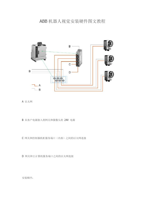
ABB机器人视觉安装硬件图文教程
A 以太网
B 从客户电源接入到网关和摄像头的24V 电源
C 网关和控制器机柜服务端口(内部)之间的以太网连接
D 网关和主计算机服务端口之间的以太网连接
安装顺序:
如图连接下列部件和线缆。
操作
1 确保控制器电源开关已经关闭。
将Ethernet 电缆从控制器机柜服务端口(内部)连接到交换机上四个Ethernet 接口中的一个。
2
通过控制器机柜上的电缆密封套将Ethernet 电缆从每个摄像头连接到交换机上的任何可用的Ethernet 接口。
3
小心地剥掉20 毫米绝缘,将电缆捆扎在电缆密封套上的接地片上。
4 通过控制器机柜上的电缆密封套将24 VDC电源电缆从每个摄像头连接到24 VDC电源。
小心地剥掉20 毫米绝缘,将电缆捆扎在电缆密封套上的接地片上。
- 1、下载文档前请自行甄别文档内容的完整性,平台不提供额外的编辑、内容补充、找答案等附加服务。
- 2、"仅部分预览"的文档,不可在线预览部分如存在完整性等问题,可反馈申请退款(可完整预览的文档不适用该条件!)。
- 3、如文档侵犯您的权益,请联系客服反馈,我们会尽快为您处理(人工客服工作时间:9:00-18:30)。
TurtleBot Assembly Instructions
TurtleBot BOM2
ITEM QTY PART NUMBER DESCRIPTION
11468-04550-6256-32x0.625Star Drive BHCS--Black Oxide
68-04552-2000TurtleBot M-F Standoff--2inch
2 8
3168-04539TurtleBot Plate0
4468-02403-125Spacer,1/2"OD,#6ID
5168-04548USB to DIN-8Cable
6168-05036TurtleBot Cargo Bay Interconnect Board
7168-06209Kinect USB and Power Cable
8268-04540TurtleBot Plate1
9 268-04556Kinect Standoff
10 168-04546Kinect Sensor
11 468-02421-8000TurtleBot F-F Standoff
12 168-04541TurtleBot Plate2
NOTE: You will nedd a small flat head screw driver for modifying the kinect.
ITEM QTY PART NUMBER DESCRIPTION
1868-04550-625
6-32x 0.625Star Drive BHCS--Black Oxide
2468-04552-2000TurtleBot M-F Standoff--2inch Item No.
QTY
24
18
54
31
41
1
2
3
4
Remove the cover over the miniDIN Port.
Attach the rear wheel to the base of the robot.
Attach the 2 inch standoffs (Item 2) to the base plate (Item 3) using the four provided screws (Item 8).
Attach the plate (Item 3) to the base of the robot using the four provided screws (Item 8) and the spacers (Item 5).
Base Plate Assembly
3
Kinect Preperation
4
1
Slide a flat head screw driver under the grill of the kinect (Item 1) as shown and remove the grill. Do this for each grill.
2
Remove the two outside
security screws from the base of the kinect as shown.
QTY
ITEM QTY PART NUMBER DESCRIPTION
1268-04556Kinect Standoff Assembly Kinect Plate Assembly
5
Item No.
QTY
21
42
31
12
1
2
Attach the kinect standoffs (Item 1) to the base of the housing. Screw the standoff all the way in untill the it is flush with the kinect bottom.
Attach the kinect to the plate (Item 3) using the provided screws (Item 4).
NOTE: It is important to make the standoff as perpendicular to the kinect as possible so that the
camera and depth images are level to the base of the robot.
Cable Bundling
6
3
Connect the kinect USB to the Y-splitter cable.
1
Bundle the miniDIN to serial cable as shown. Make sure to leave 4 to 6 inches of cable free to connect to the laptop.
2
Bundle the kinect USB cable as shown. Make sure to leave 6 to 8 inches of cable free to route from the plate to the base of the robot.
ITEM QTY PART NUMBER DESCRIPTION
QTY
Plugging Things Together
7
1
Plug the miniDIN cable (Item 2)into the side of the create base as shown.
2
Plug in the TurtleBot power board (Item 3) into the cargo bay of the robot as shown.
ITEM QTY PART NUMBER DESCRIPTION
1168-04557Create w/Plate 0
QTY
3
Plug in the power connector of the kinect power cable (Item 4)into the TurtleBot power board (Item 3) as shown.
Hiding the Cables
8
1
Place both cable bunbles in cargo bay of the robot with the USB connectors hanging out the back of the robot as shown.
ITEM QTY PART NUMBER DESCRIPTION
1168-04557Create w/Plate 0
QTY
ITEM QTY PART NUMBER DESCRIPTION
1168-04563Create with Plate 0and Cables 2168-04540
TurtleBot Plate 1
3468-04552-2000TurtleBot M-F Standoff--2inch 4168-04558
Kinect Sensor w/Plate 1
5468-02421-8000TurtleBot F-F Standoff--8inch Putting Everything Together
9
Item No.
QTY
74
61
54
41
81
34
11
21
1
Assemble the plates from the bottom up as shown.
2
Carefully turn the TurtleBot over . Remove the bright green battery holder and insert the yellow rechargeable battery.
3
Insert the laptop between plate 1and the kinect plate as shown with the laptop hinge on the left.
4
Plug the two USB cables into the laptop at the rear of the TurtleBot.。