惠普刀片服务器硬件安装配置手册
HP刀片的配置(含详细的图解)

HP刀片的配置(含详细的图解)
刀片服务器管理OA
1、通过刀片箱正面液晶面板设置OA/ILO口管理IP地址。
2、通液晶面板上下箭头调到如下图位置按OK。
3、在下IP地址位置设置OA管理IP地址,设置完成后按左右箭头到ACCEPT ALL按OK 确定。
4、连接一台电脑,设置与OA同一网段的IP地址后,点击IE后输入OA管理IP地址后出现下图!
5、输入OA用户名及密码!用户名及密码在OA 管理板的白色标签上。
注:用户名Administrator 第一个字母大写其它小写,密码全部为大写。
6、登录后界面。
7、首先设置所有刀片ILO2的地址,见下图!
8、下图为设置交换机的配置IP地址。
9、OA FW升级位置
10、OA管理地址更改位置。
11、刀片选择位置。
12、刀片远程监控位置
13、GBE2交换机管理界面,用户名:admin 密码:admin
需安装JA V A 6
13、BROCADE 4/24 SAN SWTICH 配置界面。
用户名:admin 密码:password
14、新用户建立位置图!
15、鼠标延迟更改位置。
在点击ILO2后,请直接点击WED ADMINISTRATOR
进下图界面。
16、ILO2FW 升级位置
18、鼠标延迟更改位置。
惠普服务器说明书HP_ProLiant_BL20p

HP ProLiant BL20p第三代(G3)刀片式服务器HP是业界刀片服务器的领导者,不断推出新的刀片服务器技术。
全新的ProLiantBL20p G3是一个高性能的双路刀片服务器,可以充分满足企业级用户的需求。
BL20p G3采用了高性能的Intel 3.6GHz/800MHz Xeon处理器,带有1MB的二级缓存,并支持SAN存储功能,支持高达8GB的DDR2内存扩充,网络性能极高,带有令人惊讶的4个千兆以太网卡接口。
为了保护用户的投资,全新的BL30p G3可以与BL20p G2, BL30p, and BL40p共用基础架构组件。
用户可以灵活选择刀片服务器,并可以在相同基础架构组件中获得不同性能的服务器。
通过可选的BL20p G3光纤组件,即可升级为光纤集群运行模式。
在以光纤模式运行时,可以有效的改善系统的可用性,可以轻松扩展存储容量,并可以可靠的管理存储系统。
HP具有丰富的SAN和NAS产品供客户选择。
采用双端口的2GB速率的光纤卡为BL20p G3与HP存储设备提供高速的连接链路。
高性能•Intel®Xeon™处理器,支持扩展内存64位技术,采用800MHz前端数据总线•高达3.6 GHz处理器带有1MB二级缓存•400MHz DDR-II内存,4个内存插槽支持多达8GB内存•Ultra 320 Smart Array 6i, 可选128MB带有电池保护功能的缓存管理性•支持远程管理功能iLO可选配件•BL20p G3光纤通道适配卡,支持冗余SAN连接模式全新设计•四个集成的10/100/1000网卡产品编号说明368328-B21标配一个Intel Xeon™ 3.6GHz处理器(支持2个), 1MB二级回写缓存,1024MB内存361411-B21标配两个Intel Xeon™ 3.6GHz处理器(支持2个), 1MB二级回写缓存,2048MB内存,以及双端口光纤通道适配器347955-B21标配一个Intel Xeon™ 3.4GHz处理器(支持2个), 1MB二级回写缓存,1024MB内存347954-B21标配两个Intel Xeon™ 3.4GHz处理器(支持2个), 1MB二级回写缓存,2048MB内存,以及双端口光纤通道适配器347957-B21标配一个Intel Xeon™ 3.2GHz处理器(支持2个), 1MB二级回写缓存,1024MB内存347956-B21标配两个Intel Xeon™ 3.2GHz处理器(支持2个), 1MB二级回写缓存,2048MB内存,以及双端口光纤通道适配器标准配置(刀片式服务器)ProLiant BL20p G3刀片式服务器处理器Intel Xeon™处理器3.6 GHz/800 MHz–1MBIntel Xeon™处理器3.4 GHz/800 MHz–1MBIntel Xeon™处理器3.2 GHz/800 MHz–1MB升级能力可升级至双处理器高速缓存内存1MB二级高速缓存芯片组Intel E7520芯片组内存标配1024 MB或2048 MB双路交叉存取PC3200 DDR2 SDRAM, 工作频率400MHz (根据机型而定)最大8GB注:内存必须成对安装。
HP刀片服务器安装及配置
1.刀片與DL380,DL385的構建產線網絡的區別 2.刀片上的交換機配置 3.刀片上的交換機與服務器網卡的關係 4.刀片服務器的安裝方法
刀片與DL380,DL385的構建產線網絡的區 別
刀片服務器與380,385最大區別1,刀片上綁定了4個 cisco交換機.如圖:
這4個交換機與刀片服務器組合起來達到了380,385與負 載均衡3750組合的功能.這4個交換機相當于替代了 3750.2,刀片的web管理系統.給刀片設置web管理ip:
把pre rin 對應的端口劃到對應的vlan
第3台switch是swdl(192網段) 先劃vlan 在把對應 的端口劃到對應的vlan
第4台switch配置和第3台一樣 .
刀片上的交換機與服務器網卡的 關係
服務器上4塊網卡一一對應4台交換機.
前面介紹介紹過了:172的是第一台,10的第二 台,192的第三,第四台.當然,這是以前規劃好了 的.其實,只要了解交換機與服務器網卡之間的 關係,自己可以隨意發揮.
刀片也要掛載倒你的虛擬盤,我的虛擬光盤是G盤. 當windows copy完文件,準備安裝系統是會出現 如下介面:
大概就是告訴你系統找到擴展內存,存儲之內的 東西.在web介面ቤተ መጻሕፍቲ ባይዱ好系統 .
進入我的電腦,管理介面,看到沒,多了一塊磁盤,就 是剛剛擴展的東東.
點击右鍵,創建新的分區
一直下一步,出現如下畫面時,選擇F盤,快速格示 化
Ok到此系統就裝好了
刀片上的交換機配置
先給刀片後面的4台switch配上ip(ip按規劃的設) 進入web如圖所示
接下來需要用配置線在各個switch里設密碼,設遠 程登入(這我就不寫了) 第1台switch 是連sfc的172網段,默認到vlan1里 網線接好就ok.(要注意是3根線)1根連ilo,1根連 sfc的switch. 1根連10.252網段. 第2台switch是連10網段(image),兩條線pre,rin的 192網段. 10網段只有一個端口默認在vlan1里,這裡都在21 口.下面是兩條線pre,rin的192網段,先劃4個vlan.
HPE BladeSystem产品选型与配置指南

可选择的HPE BladeSystem刀片机箱
c7000机箱分为BTO机箱和CTO机箱两类,除非有特殊配置需要,推荐首选BTO机箱;
HP BL c7000刀片机箱10U高度,16个半高 HP BladeSystem BLc7000 c-Class Server Blade Enclosures刀片服务器槽位,最大支持6个电源模块、 10个风扇模块、8个IO插槽和2个OA; BTO机箱 681840-B21 HP BLc7000铂金版机箱(10U高度,16个半高刀片服务器槽位,带单相电源箱,1 推荐使用的c7000 BTO铂金版机箱; 个OA模块,2个2400W铂金电源模块,4个风扇,ICE 试用版License) HP BLc7000铂金版机箱(10U高度,16个半高刀片服务器槽位,带单相电源箱,1 个OA模块,6个2400W铂金电源模块,10个风扇,16个Insight Control Licenses) HPBLc7000铂金版机箱(10U高度,16个半高刀片服务器槽位,带单相电源箱,1 个OA模块,6个2400W铂金版电源模块,10个风扇,16个OneView Licenses) CTO机箱 c7000 CTO铂金版机箱; HP BLc7000 Configure-to-order Platinum Enclosure with ROHS Trial Insight 此机箱内含1个OA模块和4个风扇模块;需 681844-B21 Control License 逐项添加电源模块,电源选件,电源线, 互连模块等;
机箱 刀片产品
网络互连 管理
HPE BladeSystem配置步骤
步骤1:选择刀片机箱
步骤2:配置管理软件(可选)
步骤3:选择冗余OA(可选) 步骤4:选择I/O互连模块 步骤5:为刀片机箱配置PDU或电源线 步骤6:配置刀片概览
刀片服务器系统硬件安装手册

刀片服务器系统硬件安装手册刀片服务器是一种高密度、高效能的服务器系统,它的用户可以灵活地根据需求调整服务器资源,提高数据中心的利用率和性能。
在正式使用刀片服务器系统之前,必须对系统进行硬件安装,下面是一份2000字的刀片服务器系统硬件安装手册。
第一部分:准备工作1.确认机房环境:确保机房具备安装刀片服务器系统的条件,包括足够的通风与散热设备、安全可靠的电源、合适的地面接地等。
2.准备材料和工具:准备好所需的刀片服务器系统硬件包,包括刀片服务器、机架、电源线等。
同时,备齐工具,例如螺丝刀、钳子和网线等。
第二部分:机架安装1.确定机架位置:根据实际需要确定机架的位置,并确保机架与地面垂直。
同时,预留足够的空间以便安装和维修刀片服务器系统。
2.固定机架:使用螺丝将机架固定在地面,确保其稳固可靠。
第三部分:电源连接1.连接电源线:将电源线插入机架顶部的电源插座,确保插头与插座连接牢固。
2.连接UPS:如果系统使用了UPS供电,将UPS的输出线与机架顶部的电源插座连接,确保连接紧固。
第四部分:刀片服务器安装1.打开机架:打开机架的左右侧门,并将门固定在机架两侧的支架上,以便安装刀片服务器。
2.安装滑轨:根据刀片服务器的规格和型号,在机架的前后两个立柱上安装滑轨,确保滑轨长度合适。
3.安装刀片服务器:将刀片服务器轻轻地推入滑轨中,直到刀片服务器底座与滑轨连接。
4.连接电源:将刀片服务器底座底部的电源接口与机架顶部的电源插座连接。
5.连接网络:使用网线将刀片服务器底座的网口与网络交换机连接,确保网络通畅。
6.连接存储:如果系统需要连接存储设备,使用适当的存储接口将刀片服务器底座与存储设备连接,确保数据传输顺畅。
7.安装其他硬件组件:根据需要,安装刀片服务器其他硬件组件,如内存、硬盘等。
第五部分:整理和测试1.整理线缆:将所有线缆整理好,确保不会松动或妨碍通风。
2.测试系统:打开电源,确保系统正常运行。
检查刀片服务器系统的各项功能和性能,例如硬盘、内存、网络接口等。
HP刀片服务器安装说明
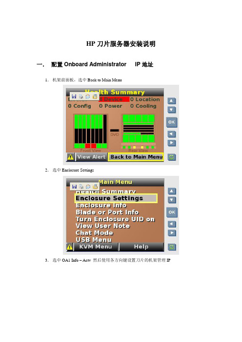
HP刀片服务器安装说明一.配置Onboard Administrator IP地址1.机架前面板,选中Back to Main Menu2.选中Enclosure Settings3.选中OA1 Info – Actv 然后使用各方向键设置刀片的机架管理IP4.点Accept All 保存设置二.设置刀片服务器IP1.IE地址栏输入刀片管理IP 192.168.211.1分别输入OA模块上密码卡片提供的用户名,密码,进入刀片管理主页面。
2.在刀片管理主页面的左侧菜单栏选Enclosure Information——Enclosure Bay IP Addressing在Subnet Mask中输入掩码在右侧图中选中Enabled前的checkbox在地址栏内输入和刀片管理IP同一网段的IP地址分别对应16个刀片服务器。
然后点Apply按钮应用,在Current Address栏中有服务器的位置显示对应的IP地址。
三.操作系统安装1.刀片管理主页面的左侧菜单栏Device Bays下的号码为刀片服务器在机框中的位置号。
2.进入一刀片服务器,点iLO在右侧的Processor Information 下选Integrated Remote Console (IE页面模式)或选Integrated Remote Console Fullscreen(全屏模式),建议选前一项,进入到单个刀片的操作页面。
注:如果没有操作系统,页面为硬件反复自检状态。
3.点击操作页面的VIRTUAL MEDIA 按钮,加载操作系统光盘镜像:点击Image 后的Mount按钮)或加载操作系统光盘:点击盘符后的Monut 按钮。
加载光盘前状态:加载光盘后状态:4.点击操作页面的电源按钮,点中Reset System 按钮,重启对应的大片服务器。
5.服务器重启,自检,光驱启动,进入操作系统安装状态。
与正常的系统安装一样。
操作系统安装结束,启动计算机进入登陆页面(2003为例),点击CAD按钮,选Ctrl -Alt-Del,输入用户名密码,进入操作系统。
刀片服务器使用手册
刀片服务器使用手册一、刀片服务器的介绍刀片服务器是公司应用服务中的一部分,是在标准高度的机架式机箱内可插多个卡式的服务器单元,实现高可用和高密度。
公司应用中使用的刀片服务器为HP 460C G6(以下简称刀片服务器)。
刀片机每一块“刀片”实际上就是一块系统主板,可以通过“板载”硬盘启动自己的操作系统,在集群中插入新的“刀片”就可以提高整体性能。
二、部署情况刀片服务器网络拓扑结构配置如图:其中每台刀片服务器各有两个网卡,分别连接到每台刀片的交换机上再各通过一条光纤线路连接到核心交换机上。
三、刀片服务器的配置1、配置刀片机箱IP地址使用HP c-class bladc server的OA远程管理端口安装设备onboard administrator card .1) 通过小液晶屏设置OA的IP地址:先选中enclosure settings2) 进入enclosure settings后,设置OA IP Address 192.168.1.1设置完成后选Accpect all2、通过刀片机箱IP地址,登录刀片进行配置1)通过终端IE6.0浏览器输入刀片服务器的OA口的IP地址:192.168.1.1;输入机器前方的纸片的出厂OA的用户名和密码登录。
2)登录后进入Rack Overiew界面,把刀片的硬件状态以图片方式展现3)第一次安装c-class刀片,直接进入first time setup wizard4)进入Configuration Management,快速重载配置好的OA设置5)Rack and Enclosure Settings,设置名称、时间、时区等6)Administrator Account Setup设置管理员账户,PIN protection可以启用设置PIN Code来给刀片前面的液晶屏设置密码7)Local User Accounts添加、管理账户8)设置OA IP Address9) EBIPA Settings可以启用给每个插在机框上的刀片分配IL02的地址,每个插在机框上的网络设备自动分配管理地址10)Directory Settings可以启用LDAP group认证模式进入OA,再次进行设置11)Onboard administrator Netwirking Settings,对OA启用DHCP或静态IP地址12)Enclosure SNMP Settings设置网管协议13)Power Management,电源管理设置三种模式:N+N冗余,N+1冗余,不冗余动态电源保护模式和输入功率限制14)初次安装设置完成。
HP刀片服务器硬件配置安装手册V
惠普刀片服务器安装手册目录第1章刀片服务器硬件配置 (5)第2章刀片服务器硬件描述 (7)2.1刀片服务器机箱HP C7000 (7)2.2刀片服务器描述 (9)2.3刀片C ISCO 3020网络交换机 (12)2.4刀片B ROCADE 4/24SAN交换机 (13)第3章刀片服务器和机箱的连接 (14)第4章刀片服务器的安装 (16)第5章刀片服务器内存的配置 (18)第6章刀片服务器硬盘的安装 (19)第7章刀片网络交换机配置 (21)7.1通过计算机连接交换机. (21)7.2完成快速安装页面的设置 (22)7.3网络连接和配置 (25)7.3.1网络拓扑结构 (25)7.3.2网络地址规划和端口配置表 (26)7.3.3网络配置 (27)第8章刀片存储交换机配置 (29)8.1设置存储交换机IP地址 (29)8.1.1采用串口连接进行设置 (29)8.1.2通过超级终端命令行的方式访问存储交换机 (29)8.1.3设置存储交换的IP地址 (29)8.2配置存储交换机 (30)8.2.1设置时间 (30)8.2.2Disabling/enabling存储交换机 (30)8.2.3打开/关闭交换机端口 (30)8.3更改交换机的F IBRE C HANNEL DOMAIN ID (31)8.4检查交换机工作状态和配置信息 (31)第9章刀片服务器的配置 (32)9.1配置刀片机箱IP地址 (32)9.2通过刀片机箱IP地址,登录刀片进行配置 (33)第10章刀片服务器的检测 (40)10.1硬件安装配置检测 (40)10.2硬盘装配正常检验 (41)10.3操作系统正常安装检验 (41)10.4刀片服务器安装检查表 .................................. 错误!未定义书签。
第1章刀片服务器硬件配置1.1刀片服务器机箱C3000 C7000高度6U10U插槽方向横向插槽纵向插槽刀片数量8 half-height刀片或4 full-height刀片16 half-height刀片8 full-height刀片6 half-height存储8 half-height磁带机交换模块插槽(SAN/LAN) 4 Interconnect bays8 Interconnect bays 热插拔冗余电源6(每个最大功率1200W)6(每个最大功率(2250W)热插拔冗余风扇 6 Active Cool Fans10 Active Cool Fans KVM 支持Enclosure KVM不支持enclosure KVMCD/DVD Enclosure CD/DVD可选没有enclosure CD/DVDOASingle OA (phase 1)Dual OA (phase 2)Single or Dual OA capabilityTested up to 6 Gbit onMidplaneTested up to 10 Gbit onMidplane 端口位置OA Serial/USB接口在正面OA Serial/USB接口在后侧1.2刀片服务器Model BL860c BL870cCPU 2P Itanium 2 4P ItaniumMemory (w/ 4GB DIMMs)DDR2 400MHz12 DIMMs/48GBDDR2 533MHz24 DIMMs/96GB内置硬盘Two SFF bays Four SFF baysRAID (w/ BBWC option) H/W RAID 1(no BBWC)H/W RAID 1(no BBWC) — TBDNICs 4 GbE NICs 4 GbE NICsPCIe mezzanines One x4Two x8One x4One x8Form factor Single-wide Double-wide第2章刀片服务器硬件描述2.1刀片服务器机箱HP C7000HP BladeSystem C系列刀片服务器的基础架构――c7000刀片机箱采用了一系列全新的技术,提供了简化的管理、强大的处理能力、超强的网络带宽,更高效的供电和散热。
HP 刀片 C3000安装手册
HP BladeSystem c3000 Enclosure Quick Setup InstructionsPart Number 446990-003November 2008 (Third Edition)Site requirementsSelect an installation site that meets the detailed installation site requirements described in the server user guide on the Documentation CD.Pallet contentsItem NameDescription1HP BladeSystem c3000 Enclosure front cage (front view)The HP BladeSystem enclosure viewed from the frontItem NameDescription2 HP BladeSystem c3000 Enclosure chassis (rear view) The HP BladeSystem enclosure chassis viewed from the rear3 Device bay blank A mandatory insert installed in any unused device bay4 Power supply blank A mandatory insert installed in any unused power supply bay5 Power supply (quantity as ordered)The power supply for the enclosure6 Half-height device (quantity as ordered) A half-height server or storage blade7 Full-height device (quantity as ordered) A full-height server or storage blade 8Local I/O cableA cable with serial, USB, andvideo connectors that attaches to the I/O connector on the front of a blade9 Fan blankA mandatory insert installed in any unused fan bay10 HP Active Cool 100 fan (quantity as ordered) A fan that cools the components installed in the enclosure 11Enclosure/OnboardAdministrator link moduleThe module that providesenclosure-link connectivity and OnboardAdministrator/iLO/interconnect management access12 KVM module blank A mandatory cover installed in the KVM module bay13Insight DisplayA display that providesinformation about the health and operation of the enclosure 14Interconnect module (quantity and type as ordered)Components such as pass-thrus or switches that enablecommunication between the blade and the enclosure 15Onboard Administrator trayA removable tray that houses the Onboard Administrator module and Insight Display16HP c3000 DDR2 Onboard Administrator module The Onboard Administrator tray that contains OnboardAdministrator 2 and a bay for an optional HP c3000 DualOnboard Administrator module. 17*Onboard Administrator blankA mandatory cover installed in an unused c3000 Dual Onboard Administrator bay18* Interconnect blank A mandatory insert installed in any unused interconnect bay 19*Documentation CDA CD that contains detailed documentation about using the enclosure20*SmartStart CDA CD that contains SmartStart software, that optimizes single-server setup21*Printed installation instructions for blades, options, and interconnects The printed installation instructions22*Installation checklistA checklist that guides you through installation of the enclosure and its components* Not shownInstalling the enclosureWARNING: Because the fully-populated enclosure canweigh up to 131.5 kg (290 lb), remove all componentsand the front cage from the enclosure before removing theenclosure from the pallet to reduce the risk of personalinjury when moving the enclosure.CAUTION: Do not touch or bump front cage connectorpins when installing the front cage into the enclosure.CAUTION: Be sure the hinges are completely openbefore installing the front cage into the enclosure. Failureto do so can cause damage to pins and connectors.1.The enclosure can be installed in a rack or rack-freeenvironment. Select the proper location based on requirements detailed in the HP BladeSystem c3000 Enclosure Setup andInstallation Guide.2.With the enclosure still on the pallet, remove all componentsfrom the front and rear of the enclosure, and then remove thefront cage.3.(Optional) Install the enclosure into a rack. See the HPBladeSystem c3000 Enclosure Rack Template. For rack-free installations, omit this step.4.Install the front cage into the enclosure, then tighten thethumbscrews.Enclosure bay identificationBefore installing front or rear components into the enclosure, review enclosure bay numbering for each component.Full-height device bay numberingHalf-height device bay numberingPower supply bay numberingFan bay numberingInstalling the front componentsCAUTION: To prevent improper cooling and thermaldamage, do not operate the blade or the enclosure unlessall hard drive and device bays are populated with either acomponent or a blank.1.Slide the Onboard Administrator module into the bay andclose the handle.2.To access the Insight Display, press and release the panel.3.Pull the Insight Display out to lock it into place, and then tilt itfor viewing.4.Add any options to each server bladeo Additional processoro Additional memoryo Mezzanine option cards5.Choose one of the following options:o If you are installing a half-height device, omit this step.o If you are installing a full-height device, remove the half-height divider.o If you are installing a full-height device in bays 3/7 and twohalf-height devices in bays 4/8, install the mini divider.6. Remove the connector covers.7.Install the server or storage blades.NOTE: If you plan to install four HP Active Cool 100Fans, you can install up to two full-height blades or up to four half-height blades. For full-height blades, populate device bay 1, and then populate device bay 2. For half-height blades, populate the device bays in the following order: 1, 2, 5, 6.If you plan to install six HP Active Cool 100 Fans, you can install the blades in any configuration.8. Install device bay blanks into any unused device bays.If the empty bays are configured for a full-height device, jointwo device bay blanks to create a full-height blank.Installing the rear componentsCAUTION: To prevent improper cooling and thermaldamage, do not operate the enclosure unless all bays arepopulated with a component or a blank.1.Slide the fan into the enclosure until it locks in place.NOTE: The HP BladeSystem c3000 Enclosure ships withfour HP Active Cool 100 fans and supports up to six fans.Install fans based on the number of storage or serverblades installed:•For one to four half-height storage or server blades orone to two full-height storage or server blades, installfour fans in bays 2, 4, 5, and 6.•For additional storage or server blades, install six fansusing all bays.NOTE: You cannot install HP Active Cool 100 fans andHP Active Cool 200 fans in the same enclosure. TheOnboard Administrator sends an error message, and youmust remove the type of fan with the least number of unitsinstalled.NOTE: When installing a fan in the top row of fan bays,orient the fan so that the LED is in the lower right corner.When installing a fan in the bottom row of fan bays,orient the fan so the LED is in the upper left corner.2.(Optional) Slide the c3000 KVM module into the bay. Whenfully inserted, the device locks into place.3.Slide the power supply into the power supply bay until thedevice locks into place.WARNING: A risk of electric shock from high leakagecurrent exists. Before connecting the AC supply to thepower enclosures, be sure that the electrical outlets areproperly grounded (earthed).When installed in a rack, the enclosure must be used withan internal rack mount power distribution unit (PDU) oruninterruptible power supply (UPS) that uses an industrialstyle wall plug (for example, locking type NEMA or IEC309 pin and sleeve configuration) which insures a reliableprotective earth ground connection.When installed in a rack-free environment, the area mustbe designated as a restricted access area, and theenclosure must be used with a dedicated uninterruptiblepower supply (UPS) that uses an industrial style wall plug(for example, locking type NEMA or IEC 309 pin andsleeve configuration) which insures a reliable protectiveearth ground connection.Installation and maintenance must be performed bytrained service personnel.NOTE: When installing a power supply in power supplybay 1, 2, or 3, orient the power supply so the plug is onthe left side. When installing a power supply in powersupply bay 4, 5, or 6, orient the power supply so the plugis on the right side.For AC redundant (N+N power supplies) configurations, an even number of power supplies is required. For thisconfiguration, where N is the number of power supplies being used, populate the power supply bays as shown.N + NPopulate the following power supply bays1 + 1 1 and 42 + 2 1, 2, 4, and 53 + 3Populate all baysFor power supply redundant (N+1 power supplies)configurations, where N is the number of power supplies being used, populate the power supply bays as shown.N + 1Populate the following power supply bays1 + 11 and 42 + 1 1, 4, and 23 + 1 1, 4, 2, and 54 + 1 1, 4, 2, 5, and 35 + 1Populate all bays4.Slide the enclosure/Onboard Administrator link module into the bay until the device locks into place.Connecting the cables1.Identify all connectors.Item Connector Description1Enclosure link-down port Connects to the enclosure link-up port on the enclosure beneath it with a CAT5 patch cable.2Enclosure link-up port and service portConnects to the enclosure link-down port on the enclosure above it with a CAT5 patch cable. On a stand-alone enclosure or the top enclosure in a series of linked enclosures, the top enclosure link-up port can function as a service port.3 OA1/iLOOnboard Administrator 1000BaseT or 100BaseT RJ45 Ethernet connection for the HP c3000 Dual Onboard Administrator module. Use a CAT5 patch cable to connect to the management network. If the c3000 Dual Onboard Administrator module is the active Onboard Administrator, connect to this port to remotely communicate with the OnboardAdministrator, all iLO ports on each blade, and supporting interconnect module management parts. 4 OA2/iLOOnboard Administrator 1000BaseT or 100BaseT Rj45 Ethernet connection for the HP c3000 DDR2 Onboard Administrator module. Use a CAT5 patch cable to connect to the management network. If the c3000 DDR2 Onboard Administrator module is the active Onboard Administrator, connect to this port to remotely communicate with the OnboardAdministrator, all iLO ports on each blade, and supporting interconnect module management parts.2.Connect the management network with a standard CAT5 patch cable.NOTE: If more than one enclosure is installed in the rack,use a CAT5 patch cable to connect the enclosure link-down port on the upper enclosure to the enclosure link-up port on the lower enclosure.3.Connect the management link cable between c-Classenclosures in the same rack.NOTE: The enclosure link ports are designed only tosupport c-Class enclosures in the same rack. The enclosure link-up port on the top enclosure is the service port, and the enclosure link-down port on the bottom linked enclosure is unused.NOTE: The HP BladeSystem c-Class enclosure link portsare not compatible with the HP BladeSystem p-Class enclosure link ports.Mapping to interconnect portsSeveral port types are referenced in the following tables. • Examples of 1x ports are 1-Gb Ethernet (1 GbE) switch modules and Fibre Channel interconnect modules. • An example of a 2x port is a Serial Attached SCSI (SAS) interconnect module. (Reserved for future use.) •Examples of 4x ports are 10-Gb Ethernet (10 GbE) interconnect modules.NOTE: 1x and 2x port mezzanine cards interface withsingle-wide interconnect modules. 4x port mezzanine cards interface with double-wide interconnect modules.The term "1x/2x" refers to the number of interconnect lanes per port provided by the controller. The more lanes provided per port, the higher the data transmission rate coming from that port.Mapping half-height bladesThe following table lists the available configurations for half-height devices installed in device bay N (1–8)Connection Port numberConnects to interconnect bay/portCommentsEmbedded NIC NIC 1 NIC 21/Port N 1/Port N+8One single-wide Ethernet interconnect moduleMezzanine slot 1—1x or 2xcards (4x cards are notsupported in this slot)1x/2x port 1 1x/2x port 22/Port N 2/Port N+8•One single-wideinterconnect module •Only two ports will be connected. •Four portcards will only connect the first two ports.Mezzanine slot 2—1x or 2x cards1x/2x port 1 1x/2x port 2 1x/2x port 3 1x/2x port 4 3/Port N 4 Port N 3/Port N+8 4/Port N+8 One or two single-wide interconnect modulesMezzanine slot 2—4x cards4x port 1 4x port 23/Port N 3/Port N+8One double-wide interconnect moduleMapping full-height bladesThe following table lists the available configurations for full-height devices installed in device bay N (1–4)Connection Port numberConnect to interconnect bay/portCommentsEmbedded NIC NIC 1 NIC 2 NIC 3 NIC 41/Port N+4 1/Port N+12 1/Port N 1/Port N+8 One single-wide Ethernet interconnect moduleMezzanine slot 1—1x or 2x cards (4x cards are not supported in this slot) 1x/2x port 1 1x/2x port 2 1x/2x port 3 1x/2x port 4 2/Port N 2/Port N+8 2/Port N+4 2/Port N+12 One single-wide interconnect moduleMezzanine slot 2—1x or 2xcards1x/2x port 11x/2x port 2 1x/2x port 3 1x/2x port 4 3/Port N 4/Port N 3/Port N+8 4/Port N+8 One or two single-wide interconnect modulesMezzanine slot 2—4x cards 4x port 1 4x port 23/Port N 3/Port N+8One double-wide interconnect moduleConnection Port numberConnect to interconnect bay/portCommentsMezzanine slot 3—1x or 2x cards1x/2x port 1 1x/2x port 2 1x/2x port 3 1x/2x port 4 3/Port N+12 4/Port N+12 3/Port N+4 4/Port N+4 One or two single-wide interconnect modulesMezzanine slot 3—4x cards4x port 1 4x port 23/Port N+12 3/Port N+4One double-wide interconnect moduleMapping BL2x220c bladesTo support network connections for specific signals, install aninterconnect module in the bay corresponding to the embedded NIC or mezzanine signals.Connection Port numberConnects to interconnect bay/portCommentsEmbedded NICServer A: NIC 1 Server A: NIC 2 Server B: NIC 1 Server B: NIC 21/Port N 2/Port N 1/Port N+8 2/Port N+8 Two single-wide Ethernet interconnect modulesMezzanine slot 1—1x, 2x, or 4x cardsServer A: Mezz port 1Server A: Mezz port 2Server B: Mezz port 1Server B: Mezz port 23/Port N 4/Port N3/Port N+84/Port N+8•Two single-widemodules or one double-wideinterconnect module •Only two ports will be connected. •Four port cards will onlyconnect the first two ports.Bay-to-bay crosslinksFor bay-to-bay communication, the enclosure midplane provides four-trace SerDes signals between adjacent bays.Device bay crosslinksDevice bay crosslinks are wired between adjacent horizontal device bay pairs.For half-height blades, these signals connect a four-lane PCIe module to a partner blade such as a tape blade or a PCI expansion blade. For full-height blades, these signals connect a PCIe module to apartner blade in the lower adjacent bay and require a PCIe pass-thru mezzanine card installed in mezzanine connector 3. Onboard Administrator disables the device bay crosslinks in instances where they cannot be used, such as when two blades reside in adjacent device bays.Interconnect bay crosslinksInterconnect bay crosslinks are wired between adjacent interconnect bay pairs.You can enable these signals to provide module-to-moduleconnections. Onboard Administrator disables the interconnect bay crosslinks in instances where the crosslinks cannot be used, such as when two different modules reside in adjacent horizontal interconnect bays.Installing interconnect modulesServer blade signalInterconnect bay number Interconnect baylabelNotes NICs 1, 2, 3, and 4(embedded) 1—Mezzanine 1 2 Four port cards connect to bay 2Mezzanine 23,4• Four port cards • Ports 1 and 3 connect to bay 3 •Ports 2 and 4 connect to bay 4 Mezzanine 3 3,4• Four port cards • Ports 1 and 3 connect to bay 3 •Ports 2 and 4 connect to bay 4NOTE: For information on the location of LEDs and portson individual interconnect modules, see the documentation that ships with the interconnect module.1.Install the interconnect modules based on the quantity ordered and the number of fabrics in the configuration.The enclosure ships with interconnect bay dividers installed. The interconnect bay dividers must be removed before installing double-wide interconnect modules. To remove an interconnect bay divider, press the release tab, and pull the interconnect bay divider out of the enclosure.2.Install interconnect blanks in any unused interconnect bays. 3.Connect each installed interconnect module to the external connections with the appropriate cable.Powering up the enclosure1. Connect the power cables to the power supplies.2.Connect the power cables to the power source or to an installed PDU.3.Turn on the AC circuit breakers that power the power cables installed in the enclosure. Setting up the HP BladeSystem Insight DisplayWhen the enclosure is powered up for the first time, the Insight Display launches an installation wizard to guide you through the configuration process. After configuring the enclosure, the Insight Display verifies that there are no installation or configuration errors. If errors are present, the Insight Display guides you through the process of correcting the errors.To identify the enclosure, the rear enclosure UID light and the background of the Insight Display are illuminated blue when the enclosure is powered on initially.To set up an enclosure with network connectivity to the Onboard Administrator: 1.On the Enclosure Settings screen, confirm the default settings. o Use the navigation arrows to navigate to a particularsetting, and press OK . o Navigate to the ? box next to a setting and press OK to gethelp on that particular setting. 2. Confirm the Power Mode setting, which defaults to AC Redundant for the power supplies.3. If the facility must limit AC power to the enclosure, set the Power Limit Watts AC below what the power supplies draw.4.Enable Dynamic Power Savings to provide the highest power efficiency without affecting server performance.5.Record the OA1 and OA2 (if present) IP address. This information is needed when deploying the management software.o If the OA1 or OA2 IP address is 0.0.0.0., set the address.Navigate to the address, and then press OK . Use the up and down arrows to select Static IP address. Use the up and down arrows on each field to set the IP, netmask and gateway one octet at a time. Press OK when done, and then press OK again on Accept to confirm the new IP address settings. o If the address is not 0.0.0.0., record the displayed addressto use for remote login to the Onboard Administrator over the management network. 6. (Optional) Edit the Enclosure Name. The default value is the Onboard Administrator serial number.7. (Optional) Edit the Rack Name. The default value is UnnamedRack.8. Set the Insight Display PIN to prevent other users of the LCD from changing the settings.9.Navigate to Accept at the bottom of the Enclosure Settings, and press OK to accept all the settings and continue. If you aresetting up a single enclosure, proceed to step 11.10. Navigate to Accept, and press OK to apply the EnclosureSettings (Power Mode, Power Limit, Dynamic Power, RackName, and Insight Display PIN) to other linked enclosures.11.Follow the instructions on the next screen.12.Follow the instructions on the next screen.13. Open a browser and connect to the active OnboardAdministrator module using the Onboard Administrator IP address that was configured during the Insight Display installation wizard process.14. Enter the user name and password from the tag supplied withthe Onboard Administrator module to access the remote Onboard Administrator web interface and complete the Onboard Administrator first time installation wizard. To set up the enclosure without network connectivity to the Onboard Administrator, see the HP BladeSystem Onboard Administrator User Guide.Troubleshooting resourcesThe HP BladeSystem c-Class Enclosure Troubleshooting Guide provides procedures and solutions for troubleshooting HP BladeSystem c-Class enclosures. This guide explains how to use the Insight Display to troubleshoot enclosures, and it includes a flowchart to help you navigate the troubleshooting process. To view the guide, see the HP website(/support/BladeSystem_Enclosure_TSG_en). The installation is complete.For more informationFor more detailed setup and configuration information, see the HP BladeSystem c-Class Solution Overview and the HP BladeSystemc3000 Enclosure Setup and Installation Guide. You can also find information on the HP website(/go/bladesystem/documentation).© Copyright 2007, 2008 Hewlett-Packard Development Company, L.P.The information contained herein is subject to change without notice. The only warranties for HP products and services are set forth in the express warranty statements accompanying such products and services. Nothing herein should be construed as constituting an additional warranty. HP shall not be liable for technical or editorial errors or omissions contained herein.Part Number 446990-003November 2008 (Third Edition)。
HP刀片服务器安装系统教程
HP刀片服务器安装系统教程
一、JS20服务器的开机检查
1.确认服务器的供电是否正常,比如机柜电源是否插好
2.打开机柜前面板,确认HP刀片服务器的状态和灯是否正常
3.检查服务器有没有插入存储磁盘,是否能够正常运行
4.检查服务器上的网口是否可以正常连接
5.开机之前,确认服务器上的内存和CPU是否可以正常运行
二、关于HP刀片服务器安装系统的步骤
1.将安装系统的光盘插入服务器,然后启动服务器,从光驱启动安装系统
2.安装系统开始后,按照提示选择操作系统,然后按提示输入用户名和密码
3.选择安装系统的位置,然后格式化磁盘,并安装系统
4.安装系统结束后,系统会提示您安装驱动程序
5.如果要安装其他软件,可以按照提示安装,最后安装完成后,重新启动系统
6.重新启动系统后,可以根据需要配置系统和网络设置,最后完成HP刀片服务器安装系统的整个工作。
- 1、下载文档前请自行甄别文档内容的完整性,平台不提供额外的编辑、内容补充、找答案等附加服务。
- 2、"仅部分预览"的文档,不可在线预览部分如存在完整性等问题,可反馈申请退款(可完整预览的文档不适用该条件!)。
- 3、如文档侵犯您的权益,请联系客服反馈,我们会尽快为您处理(人工客服工作时间:9:00-18:30)。
目录第1章刀片服务器硬件配置 (5)第2章刀片服务器硬件描述 (6)2.1刀片服务器机箱HP C7000 (6)2.2刀片服务器描述 (7)2.3刀片C ISCO 3020网络交换机 (7)2.4刀片B ROCADE 4/24SAN交换机 (8)第3章刀片服务器和机箱的连接 (9)第4章刀片服务器的安装 (10)第5章刀片服务器内存的配置 (11)第6章刀片服务器硬盘的安装 (12)第7章刀片网络交换机配置 (13)7.1通过计算机连接交换机. (13)7.2完成快速安装页面的设置 (14)7.3网络连接和配置 (15)7.3.1网络拓扑结构 (15)7.3.2网络地址规划和端口配置表 (16)7.3.3网络配置 (17)第8章刀片存储交换机配置 (19)8.1设置存储交换机IP地址 (19)8.1.1采用串口连接进行设置 (19)8.1.2通过超级终端命令行的方式访问存储交换机 (19)8.1.3设置存储交换的IP地址 (19)8.2配置存储交换机 (19)8.2.1设置时间 (19)8.2.2Disabling/enabling存储交换机 (20)8.2.3打开/关闭交换机端口 (20)8.3更改交换机的F IBRE C HANNEL DOMAIN ID (20)8.4检查交换机工作状态和配置信息 (20)第9章刀片服务器的配置 (21)9.1配置刀片机箱IP地址 (21)9.2通过刀片机箱IP地址,登录刀片进行配置 (21)第10章刀片服务器的检测 (22)10.1硬件安装配置检测 (22)10.2硬盘装配正常检验 (22)10.3操作系统正常安装检验 (23)10.4刀片服务器安装检查表 (23)2.1 刀片服务器机箱HP C7000HP BladeSystem C 系列刀片服务器的基础架构――c7000刀片机箱采用了一系列全新的技术,提供了简化的管理、强大的处理能力、超强的网络带宽,更高效的供电和散热。
1个c7000刀片机箱可以支持16片刀片服务器。
● 高性能和高度灵活的网络连接:c7000刀片机箱背板带宽高达5TB ,可以支持4种不同的网络――以太网、光纤通道(FC )存储区域网络(SAN )、Infiniband 网络、iSCSI 和SAS (串行SCSI )。
● 全冗余设计: c7000刀片机箱采用模块化设计,所有组件都支持热插拔。
c7000刀片机箱背板是完全没有活动组件的背板,并且服务器和网络互联模块之间采用冗余的链路连接,避免了单点失效的可能。
c7000刀片机箱采用了由多个HP 专利技术的Active Cool 风扇组成的冗余热插拔散热系统。
● 更高效率:和1U 传统机架式服务器相比,功耗降低30%,占用空间减40%,连接线缆减少 94%● 模块化热插拔组件:刀片服务器、存储和其他模块化组件可以在不断电的情况下方便地添加或移除。
图一:刀片系统前视图标号描述1 刀片服务器HP C7000(10U )2 刀片服务器HP BL460c (可以安装16片)3 C7000机箱前液晶面板4 刀片服务器机箱C7000热插拔电源模块(当前配置4个)图二:刀片系统后视图标号描述1 刀片机箱HP C7000热插拔风扇(当前配置8个)2 刀片Cisco3020内置网络交换机(左右共2个)3 刀片Brocade4/24内置SAN 交换机(左右共2个)4 刀片机箱内置管理控制模块(标配1个,左侧)5刀片机箱HP C7000电源连接插口(当前配置连接4个)①② ③④ ①② ③ ④⑤2.2 刀片服务器描述图三:BL460c 刀片服务器前视图 图四:BL460c 刀片服务器内部视图1 System board thumbscrew2 Processor socket 23 Processor socket 1 (populated)4 Hard drive backplane connector5 FBDIMMs (8)6 Embedded NICs (2)7 Mezzanine connector 1 [Type I mezzanine only (shown)] 8 Battery9 Mezzanine connector 2 [Type I (shown) or Type II mezzanine] 10 System maintenance switch (SW2) 11 System board thumbscrew 12连接背板插槽2.3 刀片Cisco 3020网络交换机图五:刀片Cisco3020视图编号 描述 编号 描述1. 交换机 6. Gigabit Ethernet Port LEDs2. 扳手 7. Gigabit Ethernet RJ-45 Ports3. UID LED8. 健康指示灯 4. SFP Module Port LED9.Mode Button 5.SFP Module Ports for SX Fiber 10Switch LED Panel1 Hard drive bay 12 Power On/Standby button3 Local I/O connector 14 Hard drive bay 25 Server blade handle6 Release button 7Serial label pull tabCisco3020交换机由Cisco Systems公司设计、制造并提供支持,可无缝集成到用户现有的Cisco网络基础设施中。
Cisco Catalyst 3020刀片交换机提供了16个千兆内部互连端口,8个RJ-45 外部上行链路,其中4个端口可设置为光纤(SX)端口,2个端口可设置为内部互连端口。
2.4刀片Brocade 4/24 SAN交换机刀片SAN交换机Brocade 4、24由Brocade公司设计制造,交换机提供1Gb/ 2Gb/ 4Gb自适应的光纤通道(FC)连接,可以通过这个光纤通道网络直通模块将每个刀片服务器连接到SAN,每个模块可以提供16个对内高达4Gb的无阻塞光纤通道连接链路和8个对外的4Gb连接。
第3章刀片服务器和机箱的连接图六:刀片服务器和交换模块连接视图根据上图所示:●每台刀片服务器HP BL460c提供2个网卡(NIC1、NIC2);●每台刀片服务器HP BL460c提供1个双通道FC-HBA卡的端口(M1-1口和M1-2口);●每个C7000刀片机箱配置2个Cisco3020的网络交换机(交换机插槽1、交换机插槽2)●每个C7000刀片机箱配置2个Brocade4/24的SAN交换机(交换机插槽3、交换机插槽4)标配情况下,刀片服务器BL460C中的:●NIC1连接Cisco交换机1●NIC2连接Cisco交换机2●FC-HBA1连接Brocade SAN交换机1●FC-HBA2连接Brocade SAN交换机2第4章刀片服务器的安装移去刀片机箱服务器空挡板去除刀片服务器BL460c插槽保护盖按照下图方式安装刀片服务器第5章刀片服务器内存的配置第6章刀片服务器硬盘的安装如图取下刀片服务器硬盘挡板如图将硬盘的固定扳手打开如图方法安装硬盘第7章刀片网络交换机配置7.1通过计算机连接交换机.CautionDo not connect the switch module to any device other than the laptopor workstation being used to configure it.1.确认网线连接两端的网络端口的LED指示灯是否为绿色2.端口的LED指示灯为绿色后,等待至少30秒后,打开计算机的WEB浏览器(将计算机的IP地址设置为10.0.0.X)3.在浏览器中输入http:// 10.0.0.1 回车4.显示快速安装设置页面:配置网络参数7.2完成快速安装页面的设置5.输入下述信息在“Network Settings”设置页中a.Management Interface (VLAN ID)默认为:1b.输入新的“VLAN ID ”;VLAN ID 区间为1~1001c.在IP Address栏, 输入交换机的IP地址d.在IP Subnet Mask栏,输入交换机IP地址子网掩码e.在Default Gateway栏, 输入默认网关f.在Switch Password栏,输入交换机登录口令g.(口令为1 ~ 25 alpha字符)6.在Optional Settings中输入选项a.输入Host Name选项b.可选输入System Contact信息c.选择T elnet Access栏,可以选择Enable,通过Telnet 管理交换机d.;如果选择Enable;必须输入T elnet Passworde.其他选项如SNMP、SNMP Read Community、SNMP WriteCommunity可选配置f.选择Submit保存上述设置.7.采用新的输入的交换机IP地址连接交换机Cisco 3020 就会出现Catalyst Blade Switch 3020 设备管理界面.7.3网络连接和配置●在blade server内部网卡的连接方式上,可以采用操作系统下面的网卡绑定,可以保证在一个网卡的连接出现问题的情况下,能够自动切换到备用网卡上面。
●如果3020网络交换机或连接blade server的端口出现故障时,那么连接blade server的网卡也会down,同样可以通过blade server内部网卡的绑定来实现冗余。
●Cisco 3020和客户的外部交换机之间线路的可靠性,建议在之间的连接线路上配置trunk和port channel,可以实现线路故障时的快速切换。
在连接客户的实际生产网络时,不建议关闭或更改spanning tree的配置。
●在考虑一台cisco 3020交换机所有对外连接失效的情况下来保证blade server对外连接,建议采用cisco 的Layer 2 Trunk Failover技术,通过配置Link-state group,可以保证在一台3020对外连接全部实效时blade server的网络接口也能够同时失效来保证此时Blade server能够切换到备用接口通过备用交换机及其链路实现网络通信。
7.3.1网络拓扑结构刀片服务器网络拓扑结构配置如图:其中每台刀片服务器各有两个网卡,分别连接到两台刀片Cisco 3020交换机,3020交换机再各通过一条光纤线路连接到核心交换机6506(两台)。
7.3.2 网络地址规划和端口配置表设备名称 IP 地址 网关管理Vlan上联端口 上联设备 刀片服务器01 52.0.0.11/24 52.0.0.98 100 Gi0/17 C6506 3/6 刀片服务器0252.0.0.12/2452.0.0.98 100Gi0/17C6506 3/6注:上述IP 地址和网关信息为示例; 网络设备的VTP 设置VTP Domain: CCB (示例) VTP Pass: NONE VTP Mode: Client 网络设备的Default passwd:Console pass: cisco Enable pass: cisco Telnet pass: ciscoBlade 3020-2Blade 3020-1Catalyst 6506Catalyst 6506Gi0/1Gi0/9Gi0/1Gi0/9Gi0/17Gi0/17刀片机箱系统网络端口配置表7.3.3网络配置Access端口Vlan 配置:interface GigabitEthernet0/9switchport access vlan 121switchport mode accessspeed 1000spanning-tree portfastTrunk端口配置interface GigabitEthernet0/17switchport trunk encapsulation dot1q switchport trunk allowed vlan 62,100,121 switchport mode trunkLink state配置因建行的两台Blade 3020分别采用单一的联路上联到两台Core switch 6506,无法做到link的冗余配置,因此需要配置link state,确保在一台Switch的上联联路出现故障时,能切断下联到主机的端口,确保主机可以切换到另一网卡,通过另一个3020提交数据。