TC107104OptiXOSN380068008800设备组网与应用ISSU
基于Wi-SUN无线通信技术的碳采集计量系统的设计

物联网技术 2023年 / 第10期1380 引 言电力工业作为我国的基础民生保障行业,在碳排放方面占比较大。
在2018年国际能源署发布的数据中显示,我国电力和供热行业的碳排放约占51%,交通运输、民生行业等共占21%,其他工业占28%[1-4]。
近年来,国家电网公司为实现“碳达峰、碳中和”目标,率先发布国网“碳行动”方案,并在国家电网《关于促进能源电力消费侧“碳达峰、碳中和”工作的指导意见》 (〔2021〕196号)中指出,实现“碳达峰、碳中和”目标,一方面需要能源电力从高碳向低碳、从以化石能源为主向以清洁能源为主转变,对能源电力消费侧从电气化替代、能效提升、需求响应三个方面加强建设;另一方面还需要对碳排放进行精准计量,才可以对客户的碳排放进行精准监测,对“碳达峰”和“碳中和”的实施措施进行精准评价[5-7]。
根据我国的“双碳”政策,对电力工业生产过程中碳排放的监测和计量是势在必行的。
目前,我国在碳排放的监测与计量领域暂时没有明确的标准和体系。
为了响应市场需求,也为积极响应国家电网公司的号召,本公司依托于自身现有平台,研发基于Wi-SUN 无线通信技术的碳采集计量系统,满足国家电网对数据统计常态化的要求,完善能耗和碳排放监测体系,对于“双碳”行动的开展具有重要的意义。
1 系统方案本文研究了基于Wi-SUN 无线通信技术[8-9]的碳采集计量系统实现方法,研制出一套集碳排放监测、采集、计量功能于一身的系统,并开展定点应用。
系统架构示意图如图1所示。
碳采集器通过Wi-SUN 与电力碳计量检测分析系统连接,碳传感器提供RS 485与碳采集器连接,碳采集器之间通过Wi-SUN 连接。
该系统以Wi-SUN 无线通信模块为基础,与上层应用完成mesh 组网,深度融合各类碳传感器,依托碳传感器的监测功能,完成碳排放数据的初步提取,随后经过碳采集器内置的算法,对数据进行处理,实现碳排放数据的转换,并依托其无线通信功能,将采集计量到的数据上传到上层应用之中。
系统集成需求分析

铁道大学网络工程设计与系统集成信1103-2班组长:常永生组员:段向阳兴有永亮郭颂郭茂亮齐备第二实验楼网络需求分析说明书目录1:需求分析概述错误!未定义书签。
1.1系统所在地的地理布局错误!未定义书签。
1.2网络区域环境分析错误!未定义书签。
1.3网络系统功能概述错误!未定义书签。
2:网络系统整体构造图错误!未定义书签。
3综合布线设计错误!未定义书签。
3.1建筑群子系统错误!未定义书签。
3.2垂直子系统错误!未定义书签。
3.3水平子系统:错误!未定义书签。
3.4设备间子系统错误!未定义书签。
4 网络系统分层构建错误!未定义书签。
4.1 :各分层构建错误!未定义书签。
4.2:设备选型错误!未定义书签。
1、中心三层交换机错误!未定义书签。
2、每楼层二层交换机错误!未定义书签。
5:综合布线系统保护错误!未定义书签。
1,过压与过流的保护错误!未定义书签。
2,干扰和辐射的保护错误!未定义书签。
3,综合布线系统接地错误!未定义书签。
4 ,防火墙需求错误!未定义书签。
6 系统测试与检测错误!未定义书签。
6.1 双绞线测试容错误!未定义书签。
6.2 光缆系统的测试错误!未定义书签。
6.3系统的平安性测试错误!未定义书签。
7 工程本钱预算错误!未定义书签。
第二局部:错误!未定义书签。
效劳器配置与网络链路通信错误!未定义书签。
A:效劳器配置错误!未定义书签。
B:网络链路的配置错误!未定义书签。
第一局部:工程需求详解1:需求分析概述1.1系统所在地的地理布局第二实验楼为信息学院综合办公场所,有会议室,自习室,教师办公室,研究生培养室,实验室,值班室,设备间等房间,集会议,学习,教学于一体,入驻人员多,网络需求各异。
1.2网络区域环境分析根据办公用途和网络需求的不同,可以将第二实验楼网络区域划分为一下几个区域:教师办公区域,实验室区域,教室区域,会议室区域。
1.3网络系统功能概述第二实验楼各区域网络需求各异,网络集成设计的目的是对计算机系统进展统一设计布线,实现部系统环境的集中管理;营造稳定,高效,平安的学习和办公环境,为师生提供开放灵活的信息通道;创立部交互和外部访问功能,实现各网络域间访问和对internet的访问;终端桌面应具有一定的带宽,能流畅下载各类资源;网络系统应具有防火墙等设置,能在一定程度上抵御外部的恶意攻击;系统在一定时期后,应能根据新的设备需求或用户需求对网络进展升级换代。
神华宁煤集团10G传输骨干网系统网络规划及安全性优化

浅谈神华宁煤集团10G传输骨干网系统网络规划及安全性优化摘要:宁煤集团信息技术中心现有sdh 10g主干网(大武口-银川-宁东)中银川和大武口的设备为华为osn 3500,宁东传输设备为华为osn 7500。
目前因业务发展及安全性优化要求,两台设备的性能和槽位等已经不能满足要求,同时考虑到集团信息网络后续各基础及新兴业务对传输带宽的需求,在10g传输主干网中增加一台华为osn7500智能10g光传输设备,安装在银川核心局局点,与银川核心局现有的osn3500形成设备热备。
关键词:设备热备;10g双链路保护;网络规划;安全性优化;网络结构更合理;网络;易扩容;更可靠中图分类号:tn943.6文献标识码:a文章编号:1007-9599 (2013) 07-0000-02宁煤集团信息技术中心10g传输主干网与08年建成使用,10g传输主干网组网方式以链形式,实现着集团公司业务及各厂站业务的传送,随着宁煤集团信息化建设的发展,宁煤集团所属各厂矿站点通信网络发展和对网络带宽需求增大,神华宁夏煤业集团公司(以下简称神华宁煤集团)10g主干网传输设备,特别是银川核心局osn3500设备,设备槽位已经不能满足业务需求,如果此设备出现宕机,神华宁煤集团10g主干网上所有的业务将会中断,有严重的安全隐患;而且,银川-大武口、银川-宁东采用链的方式组网,业务保护机制薄弱,业务没有备用路由或迂回路由,集团公司的业务无法保障、严重影响了集团公司业务的可靠性,制约了集团公司光传输网络发展。
根据目前的通信网络发展需求和集团公司对光通信网络的目标要求,及时的调整思路,打破制约瓶颈。
为保证宁煤集团数字化、信息化建设,实现厂站集约化发展、精细化管理、标准化建设,必须搭建传输环网保护平台,为建设数字化、信息化企业提供可靠的通道保护奠定基础。
1银川-银北10g主干光环网网络规划及安全性优化通过对银北运营部华为光传输现有设备的性能、网络结构的分析研究,以及在运行维护中出现的问题,结合通信规划,各厂站对传输带宽的需求,采取的研究方法和技术路线:(1)针对集团公司传输网络环网建设,研究银北运营部光传输网络发展方向。
泰特TB8100分析器基站 重复器产品说明书
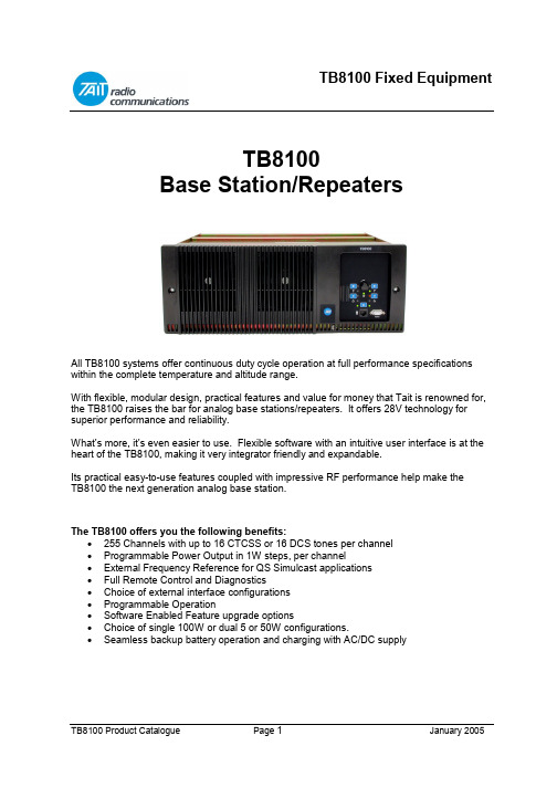
TB8100Base Station/RepeatersAll TB8100 systems offer continuous duty cycle operation at full performance specifications within the complete temperature and altitude range.With flexible, modular design, practical features and value for money that Tait is renowned for, the TB8100 raises the bar for analog base stations/repeaters. It offers 28V technology for superior performance and reliability.What’s more, it’s even easier to use. Flexible software with an intuitive user interface is at the heart of the TB8100, making it very integrator friendly and expandable.Its practical easy-to-use features coupled with impressive RF performance help make theTB8100 the next generation analog base station.The TB8100 offers you the following benefits:•255 Channels with up to 16 CTCSS or 16 DCS tones per channel•Programmable Power Output in 1W steps, per channel•External Frequency Reference for QS Simulcast applications•Full Remote Control and Diagnostics•Choice of external interface configurations• Programmable Operation•Software Enabled Feature upgrade options•Choice of single 100W or dual 5 or 50W configurations.•Seamless backup battery operation and charging with AC/DC supplyIntelligent z Flexible z High PerformanceDigital Controller DesignDesigned from the ground up, the TB8100 features a state-of-the-art RISC processor and Digital Signal Processor (DSP), providing very fast, reliable data processing through the latest in digital technology.28V TechnologyMore powerful than most base stations in its class. Tait tests the TB8100 to transmit continuously at full power with ambient air temperatures as high as 140ºF (+60ºC) at15,000 feet (4572m).Advanced Programming CapabilitiesThe TB8100’s intuitive yet comprehensive programming software with Graphical User Interface (GUI) lets you manage and program over 150 critical parameters, including all monitoring, configuration management and power management features.Convenient Modular DesignDesigned for ease of hook-up and adaptation in the field, the TB8100 is configured with front-loading modules that can be mixed and matched to meet your system needs. Whether expanding from 50 to 100 Watts, moving from single to dual channel operation, or replacing the PA or system interface board, the TB8100 gives you the flexibility to make changes in the field. A clean back-panel design hides the usual rear unit wiring clutter displaying only the connections required to link to your external radio system.User Specific ApplicationsAdditional customised programming is made easy with the TB8100 Task Manager - there's no need for intrusive hardware add-ons. TheTB8100 can readily accommodate your specific signaling, notification or alert needs. Program the unit to automatically switch to a backup base station if the self-monitor determines a problem, and choose from the wide range of alarm notification options to suit your specific solution needs. Self-Monitor CapabilityThe TB8100 manages self-monitoring parameters in its non-volatile memory, requiring no external costly monitor units, saving money, time and hassles. The advanced monitoring system will read the base status, determine the appropriate required action, and perform that action while alerting central control.Power Management SystemThe comprehensive power management system provides the ability to automatically switch between AC and DC power, to move to battery operation in the case of power failure, and to provide auxiliary battery charging and management.Complete Remote AccessibilityThe advanced intuitive interface of theTB8100 Service Kit Software makes remote management of your system simple. The self-monitoring application has dial-out capability so you are immediately notified of potential issues. Over 150 parameters on the system can be managed remotely with the TB8100 Service Kit Software.Robust SpecificationsBuilt to exceed standard specifications, the TB8100 is designed to withstand extreme temperature conditions. Engineered for maximum reliability, the TB8100 has large heat sinks, advanced cooling, and the intelligence to maintain the highest possible levels of service in adverse environments. Peak RF PerformanceWith outstanding specifications for selectivity, adjacent channel interference and fast key-up times, the TB8100 base station was designed using the best RF practices. You can depend on the RF performance of this base station even in the most extreme temperature conditions.TB8100 Base Station System PricesThe TB8100 Base Station System is shipped with the following modules included: •Subrack Front Panel with dual fans•Control Panel•Power Management Module options as selected• Power Amplifier•Reciter (Receiver/Exciter) with system interface•Service Kit (programming S/W, cable, CD)• Installation GuideSystem VHF/UHF 800MHzSingle 1-5w See price list See price listSingle 5-50w See price list See price listSingle 10-100w See price list See price listDual 1-5w See price list See price listDual 5-50w See price list See price listDual 1-5 + 5-50w See price list See price listNotes: These prices are for 12VDC systems only.For Optional Additions AddAC Power Management Unit See price listIEC Power Cord See price list12V DC, 24VDC or 48VDC Power Management Unit See price listPower Save (For Single Reciter Systems Only) See price listAlarm Reporting (Per Reciter) See price listAdvanced Profiles and Task Manager (per Reciter) See price listMicrophone See price listThese prices do not include RF equipment such as coax relays, combiners, splitters, couplers, antenna etc.For exact order details and order codes, please contact your Tait Customer Service Representative.Power Amplifiers1-5W Power AmplifierBroadband. Built-in Alarm monitoring, and diagnostics.Remotely configurable and programmable.100% duty cycle @ 60°C (140°F).2 millisecond keyup time.Programmable output power from 1 to 5W in 1W steps.Up to two 5W or 50W power amplifiers can be fitted intoa TB8100 subrack.5-50W Power AmplifierBroadband. Built-in Alarm monitoring, and diagnostics.Remotely configurable and programmable.100% duty cycle @ 60°C (140°F).2 millisecond keyup time.Programmable output power from 5 to 50W in 1W steps.Up to two 5W or 50W power amplifiers can be fitted into aTB8100 subrack.10-100W Power AmplifierBroadband. Built-in Alarm monitoring, and diagnostics.Remotely configurable and programmable.100% duty cycle @ 60°C (140°F).2 millisecond keyup time.Programmable output power from 10 to 100W in 1W steps.A limit of one 100W power amplifier can be fitted into aTB8100 subrack.Product Code Description Price TBA70B1-0000 136-174MHz, 1-5 watt PA See price list TBA70H0-0000 400-520MHz, 1-5 watt PA See price list TBA70K2-0000 760-870MHz, 1-5 watt PA See price list TBA80B1-0000 136-174MHz, 5-50 watt PA See price list TBA80H0-0000 400-520MHz, 5-50 watt PA See price list TBA80K2-0000 760-870MHz, 5-50 watt PA See price list TBA90B1-0000 136-174MHz, 10-100 watt PA See price list TBA90H0-0000 400-520MHz, 10-100 watt PA See price list TBA90K2-0000 760-870MHz, 10-100 watt PA See price listPower Management ModulesDescription: Array Single AC Power SupplyMains operated power supply. 88 to 264V input with power factorcorrection. Sufficient output power is provided to drive 1 x 100Wtransmitter or 2 x 50W transmitters. The unit has built in alarmsand diagnostics and is remotely controllable and programmable.Single DC Power SupplyA very high efficiency supply designed to run from a nominal 12, 24 or 48 VDC supply. This unit has the same output capability as the AC Power Supply. The input supply can be negatively or positively earthed. The unit has built in alarms and diagnostics and is remotely controllable and programmable.Dual (AC + DC) Power SupplyA dual power supply combining both of the above supplies. Switching from AC to DC is seamless and automatic. This option is required if the TB8100 is mains operated but is required to be powered by a backup DC supply. The DC input supply can be negatively or positively earthed. The unit has built in alarms and diagnostics and is remotely controllable and programmable.Standby Power Supply, (10W)The standby supply is highly recommended for low current consumption operation. The standby supply is used to run the Reciter alone so that the main 500 W DC supply can be switched off altogether for extended quiet periods. This unit can only be fitted to DC Supply or the Dual Supply. The low power option can only enabled for single channel operation. It is used in conjunction with the software-licensed power save feature: TBAS030.Auxiliary Power Supply / Battery Float Charger (40W output)The base station itself does not use the output of the Auxiliary Power Supply. The output is floating so it may be negatively or positively earthed.It can be configured to be on all of the time (to supply external equipment) or to be on only while mains is available (e.g. as a float charger for the battery). This module is therefore highlyrecommended for the Dual Supply and is required when the base station is to be used with TaitNetMPT1327 controllers.Single Power Supplies – see price list Product Code Input Options Output Supply OptionsAC 88-264V 10-16VDC20-33VDC40-60VDC12V Aux40W24V Aux40W48V Aux40WStandby10WTBA3001-1100 •••TBA3001-1200 •••TBA3001-1400 ••••TBA3002-2100 •••TBA3002-2200 •••TBA3002-2400 •••TBA3004-4100 •••TBA3004-4200 •••TBA3004-4400 •••TBA30A0-0100 ••TBA30A0-0200 ••TBA30A0-0400 ••Dual Power Supplies – see price listProduct Code Input Options Output Supply OptionsAC 88-264V 10-16VDC20-33VDC40-60VDC12V Aux40W24V Aux40W48V Aux40WStandby10WTBA30A1-1100 ••••TBA30A1-1200 ••••TBA30A1-1400 ••••TBA30A2-2100 ••••TBA30A2-2200 ••••TBA30A2-2400 ••••TBA30A4-4100 ••••TBA30A4-4200 ••••TBA30A4-4400 ••••Reciters (Receiver/Exciter)Reciters are available in the following bands: 136 to 156MHz, 148 to 174MHz, 174 to 193MHz,194 to 224MHz, 400 to 440MHz, 440 to 480MHz, 470 to 520MHz and 760 to 870MHz 1. Their tuning range covers a 2% subband, i.e. 10MHz at 500MHz.A Reciter includes a Receiver, Exciter, DSP, RF, and audio stages to give stable performance for the life of the product. A RISC processor controls the Task Manager, alarms system, fault monitoring, diagnostics, remote connectivity, and channel behavior.The unit has provision for an internally fitted system interface module (SIF), allowingreconfiguring of the I/O system to suit the user's requirements. There are five SIFs available.The unit is shipped with the default radio software license already installed. Other software licenses may be installed including:Alarm Reporting SoftwareAdvanced Profiles and Task Manager Software Power Saving ModesThe basic configuration includes one Reciter. An additional unit is required for any dual channel systems.Product Code Description VHF/UHF Price800MHz Price TBA40XX -YYYY Reciter with SIF included See price list See price listWhere XX is:B1=136-156MHz B2=148-174MHz B3=174-225MHz H1=400-440MHz H2=440-480MHz H3=480-520MHz K4=760-870MHzWhere YYYY is the Reciter with the following SIF:0A00 = Non-isolated 0B00 = Isolated Audio0C00 = Isolated Audio E/M 0T10 = TaitNet, MPT Trunked 0L00 = TaitNet, MPT + RS2321Note 800 MHz band covers 754-776 & 850-870 TX, 794-829 RX.System Interface CardsThe Reciters have a position inside for a System Interface (SIF) card. The SIF is responsible for all the non-RF inputs and outputs for the reciter. The SIF is interchangeable depending on the application requirements.One of the following SIFs may be selected per reciter.Non Isolated Audio D25 Connector with:Æ Balanced and unbalanced input and output audio lines, Æ 6 digital inputs, Æ 2 digital outputs, Æ 4 digital input/outputs Æ 1 coax relay drive output, Æ Tx Key & Rx Gate.Isolated Audio D25 connector with:Æ Transformer isolated balanced input and output audio lines, Æ Non isolated unbalanced input and output audio lines, Æ 6 digital inputs, Æ 2 digital outputs, Æ 4 digital input/outputs Æ 1 coax relay drive output, Æ Tx Key & Rx Gate.Isolated Audio E&M D25 connector with:Æ Transformer isolated balanced input and output audio lines, Æ Non isolated unbalanced input and output audio lines, Æ 2 digital inputs, Æ 2 digital outputs, Æ 4 digital input/outputs Æ 1 coax relay drive output, Æ Tx Key & Rx Gate, Æ Optically isolated E & M (Tx Key and Rx Gate).TaitNet, RS232D15 connector to interface directly with TaitNet system, with:Æ Balanced and unbalanced input and output audio lines, Æ 1 digital input, Æ 3 digital outputs, Æ Tx Key & Rx Gate Æ D9 RS232 connector.TaitNet, MPT TrunkedD15 connector to interface directly with TaitNet system, with:Æ Balanced and unbalanced input and output audio lines, Æ 1 digital input, Æ 3 digital outputs, Æ Tx Key & Rx Gate.SubracksIn order to house the modules, you need to select one of the following subracks:Description 5/50W 100W Single Reciter Systems See price list See price list Dual Reciter Systems See price list Not Available Power Save Systems See price list See price listNOTE:PowerSave is only available in Single Reciter Systems.Software Enabled FeaturesThe TB8100 Software feature enabler is a software licensing system that is used to enable advanced features of the base station.Licenses are applied on a per-feature and per-reciter basis. Alarm Reporting SoftwareThe TB8100 Base Station supports some key alarm systems that will form the backbone of any well-configured radio system. The key features are:• Task Manager initiation of Status and Alarm calls • Alarm Centre package (standalone PC application)Æ Alarm collection Æ Email forwarding• External alarm inputs to base stationThis license must be purchased on a per reciter basisAdvanced Profiles and Task Manager SoftwareSignalling :Up to 16 sub-audible receive tones (CTCSS or DCS). No limits to the combinations for CTCSS and DCS.Tx tone selectable per input tone for repeater operation. Tx tone selectable for Line Controlled base operationSignal Path:Dual audio paths on both transmit and receive.Audio filtering characteristic independently selectable for both receive paths and both transmit paths.Tx Power:Power adjustable independently for mains and battery operationChannel Spacing:Cross-system repeating possible with independently selectable receiver and transmitter bandwidth (25kHz, 20kHz or 12.5kHz)Task ManagerUp to 200 enabled tasks.Far greater scope for better system control andfault & alarm management.Advanced ProfilesUp to 16 customised channel profiles and signallingprofiles are available.Base station behaviour changes on a per-profile basis.Power Saving ModesIn power saving mode the receiver cycling time can beas slow as one second. If the PMU has a standby supplyfitted, the reciter will also switch off the main circuitryof the PMU when not needed. Power savings aretherefore dramatic. If there is line or signal activity,the power supply is completely re-booted to wake thesystem. The standby supply has been carefully optimisedto power just a single reciter, and is not suitable if thesubrack has more than one reciter.This license must be purchased on a per reciter basis.Product Code Description PriceTBAS010 Alarm Reporting Remote Control & DiagnosticsDial-up reporting and e-mailSee price listTBAS020Advanced Profiles and Task ManagerDefault profiles, 16 CTCSS or DCS tones, Dual audiopaths Full task manager (200 tasks)See price listTBAS030Power Saving ModeProgrammable low current drain features. RequiresDC Power Management Unit and standby supply.See price listStandard AccessoriesTMAA02-01 MicrophoneRequired for test transmissions. Plugs into the UserInterface. The microphone can be configured totransmit over the air or as line audio.See price listPower CordsetsProduct Code Description PriceTBA0001-AU IEC Cordset (Aust/NZ/China)TBA0001-US IEC Cordset (USA/Canada/Middle East)See price list T952-320 IEC Cordset (Singapore/UK/Hong Kong)T952-330 IEC Cordset (Mainland Europe)Service AccessoriesTBA0ST1 Calibration Test UnitThe TB8100 Calibration Test Unit is required whenusing the Service Kit to access the reciter when it isnot in the subrack.It is required for system re-tuning and extremely usefulfor system test and run-up, especially whencommissioning new configurations, and running radio diagnostics.See price listTBA0ST2 Tool KitComprising of:Control Panel Board RemoverTorx-Driver T8Torx-Driver T10Torx-Driver T20Screwdriver PZD-2Screwdriver Medium Flat BladeTuning Tool Cer 2.2mmTuning Tool 5CCESocket Head M3 nutsTool bagSee price list。
100GOTN系统架构和建设应用探讨
100G OTN系统架构和建设应用探讨发布时间:2022-07-18T05:10:02.396Z 来源:《中国科技信息》2022年第33卷3月5期作者:姚灵智高昊[导读] OTN系统架构为三层,包括光通路层(OCh)、光复用段层(OMS)、光传输段层(OTS),姚灵智高昊中国人民解放军31401部队125分队辽宁大连 116000摘要:OTN系统架构为三层,包括光通路层(OCh)、光复用段层(OMS)、光传输段层(OTS),各层之间衔接紧密,相邻层之间是Client/Server关系。
其中最重要的为光通路层,OTN系统的主要功能均由该层实现。
关键词:100G;OTN系统;1 100G OTN系统架构1.1 光通路层(OCh)网络光通路层能够通过光通路实现接入节点之间的数字信号的传送,并定义光通路的带宽、光信号的信噪比,还能够实现通路外开销封装。
光通路层分为三个子网络层,分别为光通路子层网络、光通路传送单元子层网络、光通路数据单元子层网络。
光通路层网络信号均为逻辑信号。
光通路子层网络实现传送OTUk信号的光通路层净荷和相应的光通路层的开销区。
其中,OTUk中k的值可分为1、2、3、4。
光通路传送单元子层网络传送ODUk信号的光通路传送单元子层网络净荷区和开销区。
其中,ODUk中k的值可分为0、1、2、2e、3、4。
光通路数据单元子层网络传送ODUk净荷区以及与传送相关联的开销。
1.2 光复用段层(OMS)网络OMS层网络通过OMS路径实现光通路在接入点之间的传送,其特征信息包括OCh层适配信息的数据流和复用段路径终端开销的数据流,均为逻辑信号,采用n级光复用单元(OMU-n)表示,其中n为光通路个数。
光复用段中的光通路可以承载业务,也可以不承载业务,不承载业务的光通路可以配置或不配置光信号。
1.3 光传输段层(OTS)网络OTS层网络通过OTS路径实现光复用段在接入点之间的传送。
OTS定义了物理接口,包括频率、功率和信噪比等参数。
智源流量探针硬件参考指南说明书

关于本手册本手册为硬件参考指南,帮助用户正确安装山石网科的设备。
本文档禁止用于任何商业用途。
获得更多的文档资料,请访问:https://针对本文档的反馈,请发送邮件到:***********************联系信息北京苏州地址:北京市海淀区宝盛南路1号院20号楼5层地址:苏州高新区科技城景润路181号邮编:100192 邮编:215000联系我们:https:///about/contact_Hillstone.html山石网科https://TWNO: TW-HW-Sensor-CN-V3.0-Y20M09目录产品介绍 (1)前面板 (1)后面板 (2)扩展模块 (3)常用工具 (3)注意事项 (4)安装上架导轨 (4)将设备安装到标准机架上 (5)安装扩展模块 (6)卸载扩展模块 (7)连接交流电源 (7)通过配置口(CON口)访问设备 (7)通过WebUI界面访问设备 (7)连通网络 (8)单机部署 (8)集群部署 (10)完成配置 (19)关机 (19)产品介绍前面板SG-6000-ISC1050S的前面板有1个配置口(CON口)、1个MGT管理口、2个USB口、2个通用扩展槽、7个千兆电口以及若干个状态指示灯。
如图所示:SG-6000-ISC1020S设备的前面板有1个配置口(CON口)、1个通用扩展槽、1个MGT管理口、2个USB 口、5个千兆电口以及若干个状态指示灯。
如图所示:SG-6000-ISC1020S-AD设备的前面板有1个配置口(CON口)、1个通用扩展槽、1个MGT管理口、2个USB口、5个千兆电口以及若干个状态指示灯。
如图所示:SG-6000-ISC1010S的前面板有1个配置口(CON口)、1个通用扩展槽、1个MGT管理口、2个USB口、3个千兆电口以及若干个状态指示灯。
如图所示:SG-6000-ISC1010S-AD的前面板有1个配置口(CON口)、1个通用扩展槽、1个MGT管理口、2个USB 口、3个千兆电口以及若干个状态指示灯。
信号集中监测系统
智慧法院Campus OptiX全光网络解决方案

智慧法院Campus OptiX全光网络解决方案智慧法院全光解决方案场景2法院园区网络趋势与挑战1智慧法院全光解决方案亮点3目录智慧法院全光解决方案应用案例及产品4最高法推进信息化发展的决定法院信息化1.以五年发展规划为牵引,加强顶层设计2.以拓展融合为重点,加快系统建设3.与系统建设和应用需求相适应,强化保障体系4.以大力推广和质效评估为杠杆,提升应用成效业务云化驱动法院园区网络架构革新业务云化100% 企业@202585% 业务@2025连接IoT千亿连接数@202550G 每用户每月@2025管理融合办公/安防/IoT 一网融合多网统一管理园区业务三大趋势园区网络新诉求架构简单流量南北化桌面云要求低时延灵活演进宽带/WiFi/5G/IoT 灵活接入园区带宽需求大幅增长智能运维多网融合管理运维智能化,降低人员依赖度智慧法院全光解决方案场景2法院园区网络趋势与挑战1智慧法院全光解决方案亮点3目录智慧法院全光解决方案应用案例及产品4法院网络架构图简架构易演进智运维➢支持业务扩展,一纤多业务,面向IPv6能力ready ➢10G->50G->100G PON 共平台;➢自研芯片ONU支持对称10G PON ,布线免改动,节省30%工程TCO➢开局即插即用免调测,提升部署效率60%➢企业轻量级网管eSight ,无源ODN 免维护➢扁平大二层极简架构,光进铜退➢节省80%能耗和机房,90%布线空间➢业界领先端到端IP+光全光网络外网终端分光器智慧办公智慧服务ONU智慧安保ONU智慧法庭数据中心DMZ网管管理中心视频监控/安防中心法院内网涉密专网机房ONUONUOLT OLTONUONU OLTOLT语音PBXONU ONUTypeB 双归属保护运营商语音专线办公内网外网涉密网安防/设备网交换机羁押网羁押区⚫采用网络箱方式安装⚫小、中、大法庭可以选择不同规格ONU安装方式电话电脑电脑电脑ONU 选型EA5821: GPON/XG-PON, 24GE POE P805E:XGS-PON, 24GEP613E: GPON, 4GE POE+4GE P603E: GPON, 8GE接入点>8接入点<=8内网、外网光纤直接进入到法院法庭。
- 1、下载文档前请自行甄别文档内容的完整性,平台不提供额外的编辑、内容补充、找答案等附加服务。
- 2、"仅部分预览"的文档,不可在线预览部分如存在完整性等问题,可反馈申请退款(可完整预览的文档不适用该条件!)。
- 3、如文档侵犯您的权益,请联系客服反馈,我们会尽快为您处理(人工客服工作时间:9:00-18:30)。
OSN 6800 OTM典型配置
以光合波器M40V 和光分波器D40V 构成的 40 波OTM 设备为例,共需要1 机柜,3 个 子架。
SCC 单板优先插放在IU18。若配置备用SCC 单 板,则插放在IU17。
优先在IU16 配置监控信道单板。 FIU 插放在IU15,然后在其左侧插放光放大板
目录
2. 站点类型
2.1 OTM 2.2 OLA 2.3 FOADM 2.4 ROADM
OTM
OTM站点需要的功能单元
波长转换单元(LQM,TOM+NS2,LSX ···) 光分波/合波单元(M40,D40,MR2···) 光放大单元(OAU1,OBU1 ···) 光监控接入/解出单元(FIU) 光监控信道处理单元(SC1) 主控单元(SCC)
8800 FOADM典型配置(M40/D40)
以光合波器M40 和光分波器D40 构成的两个传输方向各分插复用32 波的
FOADM 设备为例
FOADM(MR2/MR4/MR8)
TM
RM1
TM2
RM
SC2
RM
TM1
RM2
TM
IN
F
I
OUT
U
OA OA
IN OUT
D1
M R X
A1 Dx
MO MI
OTM
Rx
OTU OUT M01
Rx
OTU
OUT M02 MM 440
OUT
IN
OA
OUT
Rx
OUT M40 V0 OTU
Tx
OTU
Tx
OTU
Tx OTU
IN D01
IN D02 MD IN 440
IN D40 0
RM
SC1
TM
OA
OUTINDCM来自RCF OUT
TM
I
RM
U IN
TC
可调衰减器 固定衰减器
TC107104OptiXOSN38 0068008800设备组网与
应用ISSU
2020/9/13
OptiX OSN 3800/6800 /8800设备组网与应用
前言
本课程主要介绍OptiX OSN 3800/6800/8800产品的系统组成和 功能特性,以及产品的典型应用模式和组网能力。
目录
光层
系统架构
WXC
G.709接口 X-ADM L2 SW 支路接入
GMPLS 控制平面
L0
灵活光层 3800/6800/8800
• C波段40/80 波 2.5G/5G10G/40Gb/s • 支持MESH组网的多维ROADM • 全波段可调OTU
L1
ODU1/ODU2/GE/Any ADM 3800/6800 ODU1/ODU2 ADM 8800
以光合波器M40 和光分波器D40 构成的两个 传输方向各分插复用10 波的FOADM 设备为 例
光放大器放于子架的两侧。同一方向的接收端 和发送端的光放大器配置在子架的一侧。
FIU 分别插放在IU1 和IU15,然后依次插放光放 大器。
这里东西向的OTU和合波分波单元分子架插放 。
当子架通过主从方式进行级联时,主子架推荐 配置主控1+1 保护。
• GE、2.5G、 10G业务调度 • 多业务交叉调度 • 特有的子波长保护
L2 灵活的二层业务汇聚 3800/6800
• 内置二层汇聚 • VLAN, Q in Q • 99.999% QoS • Ethernet OAM
基于光、电统一GMPLS 控制平面
目录
1. 产品特征和地位 2. 站点类型 3. 应用模型和系统互联 4. 组网的基本要素
。 OTU 配置时按照频率由小到大,多子架间从
下到上,单子架内从左至右的顺序进行配置 。
OSN 8800 OTM典型配置
以光合波器M40 和光分波器D40 构成的 20 波OTM 设备为例,共需要1 机柜,1 个子架。
当OSN 6800 的子架和OSN 8800 的子架同 时存在时,建议将监控单元单板配置在 OptiX OSN 6800 的子架上,以节省OSN 8800 的槽位。
TM
RM IN
F
OA
OUT I
U
OA
M 4 0
M 4 0
RM1
TM1 D01
D 40 Dn
SC2
OTU
TM2
RM2
M01
Mn
MM 440
0
M
MD
40
OTU
440
0
C偶数波段配置。
OO TT UU
OO TT UU
RM
TM
OA
OUT
F
I IN
OA
U
可调衰减器 固定衰减器
6800 FOADM典型配置(M40/D40)
MI MO
Ax D1
M OUT
R
X
IN
A1 Ax Dx
OA OA
F OUT
I
IN
40 10G
OptiX OSN 6800
STM-64
OptiX OSN 6800
汇聚层
OptiX OSN 2500
OptiX OSN 3800
OptiX OSN 1800
STM-16
STM-4 STM-4/1
OptiX OSN
1500 OptiX OSN 3800
STM-4 STM-1
接入层
电层
1. 产品特征和地位 2. 站点类型 3. 应用模型和系统互联 4. 组网的基本要素
网络层次
iManager T2000
80 10G
OptiX OSN 8800
OptiX OSN 8800
80 40G
OptiX OSN 8800
骨干层
OptiX OSN 7500
OptiX OSN 3500
STM-16
FOADM
FOADM站点需要的功能单元
波长转换单元(LQM,TQS+NS2,LSXL,LSXR ···) 光分波/合波单元(M40,D40,MR2···)
光放大单元(OAU1,OBU1 ···)
光监控接入/解出单元(FIU) 光监控信道处理单元(SC2) 主控单元(SCC)
FOADM(M40/D40)
OLA
DCM
TC
IN
F
RM
I
OUT
TM
OOAAU1
OUT
IN
OUT RC
TM1 S RM2
F OUT
TM
C
I
RM1 2 TM2
RM
IN
U
RC OUT
OA IN
TC U
DCM
可调衰减器
OLA 的典型配置
当OSN 6800 的子架和OSN 8800 的子架同时 存在时,建议将该类站点配置在OSN 6800 的子架上。
OTU 配置时按照频率由小到大,多子架间 从上到下,单子架内从左至右的顺序进行 配置。
SCC 单板优先插放在IU28。若配置备用 SCC 单板,则插放在IU11。
OLA
OLA站点需要的功能单元 光放大单元(OAU1,OBU1 ···)
光监控接入/解出单元(FIU) 光监控信道处理单元(SC2) 主控单元(SCC)