1.0M,1.1M,1.2M,燃气扒炉使用说明书 (英文)
燃气壁炉使用说明书

Page 1INSTALLER:Leave this manual with the appliance.CONSUMER:Retain this manual for future reference.NOTICE: Crushed glass and ceramic fiber rocks may differ in appearance from those shown inthis manual.INSTALLATION INSTRUCTIONSAND OWNER’S MANUAL37707-1-0617Page 24. Glowing embers included with the fireplace may beplaced in small portions (dime size) over the round ports on the burner or area near the ports. Do not use glowing embers over the rectangular ports on the burner or area around the pilot. See Figure 5.5. Place decorative rocks and sticks in areas on theburner cover or modern cover. Do not place them over any burner ports. Figure 2 shows the location on rock base (A) that should remain open.6. Replace glass door and barrier screen as indicated infireplace manual.CRUSHED GLASS (place in shaded area only)Figure 3PIN LOCATIONS FOR ROCK (A) PLACEMENTFigure 4GLOWING EMBERS (place in shaded area only)Figure 5ATTENTION: The position of the crushed glass and ceramic fiber rocks is critical for the safe and clean operation of this fireplace. Sooting and other problems may result if the crushed glass and ceramic fiber rocks are not properly placed in the fireplace.ROCK, EMBER AND CRUSHED GLASS PLACEMENT1. Remove barrier screen and glass door on fireplaceusing instructions from the fireplace manual.2. Place thin layer of crushed glass (sold separately) overthe burner surface and cover as shown in Figure 1. One bag of crushed glass is sufficient on DVCC(32,36)models, and one and a half bags for DVCC42 models. Crushed glass may be anywhere on burner cover, modern cover, or burner except the rectangular ports and burner around the pilot. See Figure 3.3. Place rock base (A) onto the burner (pins 1, 2 and 3).See Figure 4.Figure 1Empire Comfort Systems Inc.Belleville, ILIf you have a general question about our products, please e-mail **************************. If you have a service or repairquestion, please contact your dealer.Arocks in this area.123。
扒炉使用说明书

JZH-RG JZH-RGA JZH-TRG JZH-TRGA ZH-RG ZH-RGA ZH-TRG ZH-TRGA燃气扒炉使用说明书本厂管理体系符合ISO 9001:2000标准要求本企业系列产品均由中国人民保险公司承保使用目录:1、一般事宜 (1)2、安装说明2.1安装图 (2)2.2外型尺寸 (2)2.3安装 (3)2.4技术参数 (4)2.5控制旋钮 (4)2.6更换喷嘴 (5)2.7喷嘴一览表 (6)3、操作原理3.1点火 (6)3.2熄火 (6)4、使用与保养4.1使用注意事项 (7)4.2警告 (8)4.3用户说明 (8)5、故障排除 (9)6、保修卡 (10)1、一般的事宜◆该炉的安装,初次使用和维修都应该由专业人士或已取得安装操作证的人士,或生产商批准特许的人士来进行。
◆在操作安装与维修时,请注意仔细按照以下步骤去做以确保安全使用此机器。
◆保管好说明书,以使将来有疑问所用或留给下一个操作者使用。
◆去除外包装,保证机器的完整性,如有疑问,请不要使用机器,并请专家咨询,不要将包装材料,放在小孩可以拿到的地方,以免发生危险。
(材料是塑料袋,钉子等)◆该设备仅用于商用,必须由技术熟练的人员操作。
◆不使用机器时或操作人员不在时,必需要关掉机器,以免发生危险。
◆修理时请叫专业维修中心人员来维修,并使用原装配件,如不遵循以上要求,可能会危及机器的安全性能。
◆此机器是作为一种商业用途并不适用于其它用途,否则会引起危险。
◆机器的安装必须由专业人士按照制造商提供的说明书来进行。
◆不能用水直接冲洗。
◆适当地定期清洗不锈钢表面,防止表面氧化和化学作用破坏机器。
警告:!该设备只使用于低压燃气阀!任何改装、以及不正确的安装、调整、维修或维护都可能导致财产损失或人员伤亡,如需调整或维修应与供应商联络,并由经过训练的专业人士进行。
!为了您的安全,请不要在本产品附近存放或使用易燃易爆气体、液体或物品。
!此设备有温度控制,干烧久了将自动切断主气源。
欧宝锅炉说明书
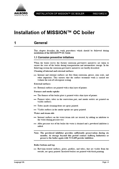
Installation of MISSION™ OC boiler1 GeneralThis chapter describes the work procedures which should be followed duringinstallation of the MISSION™ OC boiler.1.1 Corrosion preventive initiativesWhen the boiler leaves the factory corrosion preventive initiatives are taken toensure the state of the boiler during transportation and intermediate storage. In thefollowing section the corrosion preventive initiatives are briefly described.Cleaning of internal and external surfaces−Internal and external surfaces are free from corrosion, grease, iron scale, and other impurities. This ensures that the surface treatment work is carried outwithout the risk of subsequent scaling.External surfaces−External surfaces are painted with a thin layer of primer.Furnace and smoke uptake−The furnace of the boiler plate is painted with a thin layer of primer.−Furnace tubes, tubes in the convection part, and smoke outlets are painted on visible surfaces.−Tubes inside cleaning doors are spray-painted.−Visible surfaces in the smoke uptake are spray-painted.Water and steam side−Internal surfaces on the water/steam side are treated, by adding an inhibitor to the water during pressure test.−After pressure test of the boiler the water is drained and a powdered inhibitor is added.Note: The powdered inhibitor provides sufficiently preservation during sixmonths. At storage beyond this period contact Aalborg Industries orpreserve the boiler again with VCI-609 powder inhibitor.Boiler bottom and top−Raw/non-treated surfaces, plates, profiles, and tubes, that are visible from the outside, are spray-painted. Insulated boilers are painted with black painting.Closing of boilers−Manholes and hand holes are closed with cover plates and gaskets.−Flanged sockets are closed with plastic tube closing plugs.−Smoke outlets and inlets, if provided, are closed with galvanised plates.−If no burner is mounted, the fire hole in boiler front plate is closed with a galvanised plate.−Bolts, blot supports, tap holes, hinges, etc., are greased with a protective agent.2 Handling and lifting the boilerWhen the boiler is delivered, the exhaust gas inlet tube is not fixed to the connectionring, and the tube is pushed up against the bottom of the furnace. By doing so, theboiler can be placed into an up-right position without risk of damaging the tube.During installation of the boiler, the exhaust gas inlet tube must be placed in thecorrect position and fixed to the connection ring.Furthermore, the boiler is delivered with the transportation supports mounted.Note: If the boiler unit is stored for a period of time before it is mounted in theship, it must be stored inside to protect against corrosion caused by rain,pollution, etc. When the boiler unit has been installed in a ship stillunder construction, it may also be exposed to rain, pollution, etc.Therefore it must be covered with a waterproof tarpaulin.Step A:Whether the boiler is placed on the quay or directly in the ship, thetransportation supports should not be removed before the boiler is turnedinto an up-right position. The boiler should always be placed on a planefoundation. This secures the boiler foundation from deformation.Step B:The boiler must be turned into an up-right position by the use of two cranesas shown in Figure 1.Step C:The transportation supports must be cut inside the insulation. Insulationplates for covering this area are supplied with the boiler.Step D:Finally the boiler can be installed in the ship by lifting it as shown in Figure2.Note: The lifting wires should at least be dimensioned to a force equal to theweight of the boiler. The weight appears from the technical data.Turn the boiler into an up-right positionFigure 1 Oc_instal02.cdr Lift the boiler into the shipFigure 2 Oc_instal03.cdr3 Installation of the boilerWelding to the deck/ship structureFigure 3 Oc_instal04b.cdr3.1 Welding to the deck/ship structurePrior to installation of the boiler, it must be ensured that the deck or ship structure, onto which the boiler should be welded, is sufficiently plane and has the adequate strength to support the boiler. Furthermore, the boiler foundation in the ship must have the sufficient stiffness to avoid that vibrations from the ship are transformed toSmoke outlet box6Deck or tank topExhaust gasinletExhaust gasoutletMin. 10For boilers with counter flange,diameter above 3,000 mmFor boilers with shell,diameter up to 3,000 mmSmoke outlet boxFlue gas outlet flangethe boiler. The vibration levels generated by other sources than the boiler itself and measured on the boiler body during normal operation loads of the ship should not exceed an overall velocity of 30 mm/s (peak) in the frequency range 5 –50 Hz measured in any direction.After lining-up, the boiler must be welded to deck/ship structure as shown in Figure 3. The cut-outs in the foundation of the boiler may under no circumstances be covered or sealed. This is due to the fact that there should always be an air circulation below the boiler.Note: If the boiler is installed on a tank top, the distance between the bottom of the furnace and the tank top must be at least 760 mm or according to the rule of the classification society.3.2 Connection of the exhaust gas inlet/outlet and smoke outlet The inlet and outlet sections can be delivered with both flange and counter flange. To absorb the thermal expansions when the boiler is heated, expansion bellows must be installed. The bellows must be installed right before and after the exhaust gas inlet/outlet and right after the smoke outlet box. The thermal expansion can be estimated to 2.15 mm/m both in horizontal and vertical direction.Attention: The boiler may under no circumstance carry the weight of the flue gas funnel or the exhaust gas funnel. Fix-points should be arrangedfor the funnels right below and above the boiler.The exhaust gas inlet piping should be designed so that the exhaust gas flow is evenly distributed over the entire inlet cross-section area. An uneven distribution may result in a reduced steam output as well as an increased exhaust gas pressure drop across the boiler. The exhaust gas inlet piping should furthermore be constructed so that no washing water can enter the turbo chargers of the main engine. Welding of the smoke outlet boxThe smoke outlet box must be welded to the flue gas outlet flange with a gas proof fillet welding as shown in Figure 3. The welding must be placed on the inner side of the flue gas tube as it is important not to damage the insulation plates with welding glows.Recommended dimension of the flue gas funnelThe following table shows the recommended dimension of the smoke funnel. The stated dimensions imply a smoke velocity of 25 m/s and a draft loss of maximum 5-10 mm WC. If these conditions cannot be fulfilled, the diameter should be increased.Recommended dimension of the smoke funnelBoiler type (oil fired section) Dimension (mm) MISSION™ OC 1000 DN 200 MISSION™ OC 1250 DN 250 MISSION™ OC 1600 DN 250 MISSION™ OC 2000 DN 300 MISSION™ OC 2500 DN 300 MISSION™ OC 3150 DN 350 MISSION™ OC 4000 DN 400 MISSION™ OC 5000DN 450Table 1Welding of the exhaust gas inlet tubeThe exhaust gas inlet tube must be placed in the correct position and fixed to the connection ring as shown in Figure 4. Welding of exhaust gas inlet tubeFigure 4 Oc_instal05.cdrTransport and storage position of the exhaust gas inlet tubeADetail ASite weldSite weldM a x . 15 m mInstallation position of the exhaust gas inlet tubeBoiler foundationBottom plate End tube plate3.3 Connection of pipes and boiler mountingsNote: The connection pipes to the boiler mountings must be arranged in such a way that the thermal expansion of the boiler and the piping system donot transform any significant forces to the sockets on the boiler or theboiler mountings. The thermal expansion can be estimated to 2.15 mm/mboth in horizontal and vertical direction.3.3.1Connection of pipesThe connection of pipes to the boiler mountings should be performed by means of welding neck flanges or slip-on flanges. Figure 5 illustrates the piping connections for the boiler.3.3.2Connection of boiler mountingsThe boiler mountings are pre-mounted on the boiler body. Counter flanges can be supplied (option) for the connection pipes. The counter flanges must be dismantled from the boiler mountings and welded to the system pipe.The open ends of the mounting connections are closed with plastic plugs. These plugs must be removed before the mountings are connected to the system with gaskets, supports, and bolts.Connection of pipesSlip-on flanges Welded neck flanges Figure 5 flanges_install.cdrFlange and tube sizesDIN tubes JIS tubesDN sizeInsidediameter offlange (mm)Outsidediameter oftube (mm)DN sizeInsidediameter offlange (mm)Outsidediameter oftube (mm)DN15 22.0 21.3 DN15 22.0 21.7 DN20 27.5 26.9 DN20 27.5 27.2 DN25 34.5 33.7 DN25 34.5 34.0 DN32 43.5 42.4 DN32 43.5 42.7 DN40 49.5 48.3 DN40 49.5 48.6 DN50 61.5 60.3 DN50 61.5 60.5 DN65 77.5 76.1 DN65 77.5 76.3 DN80 90.5 88.9 DN80 90.5 89.1 DN100 116.0 114.3 DN100 116.0 114.3 DN125 141.5 139.7 DN125 141.5 139.8 DN150 170.5 168.3 DN150 166.0 165.2 DN200 221.5 219.1 DN200 217.0 216.3 DN250 276.5 273.0 DN250 268.5 267.4 DN300 327.5 323.9 DN300 319.5 318.5 Table 2。
24 28 32 MBS W TOP IT 壁挂式燃气炉 产品说明书

壁挂式燃气炉—高效率—采暖/热水两功能产品使用说明书请详细阅读本说明书内各项安装、维修等说明,并保存好此说明书,以便以后查阅。
设备的安装、维修工作必须由专业技术人员来完成。
目录总说明 2 简述 3 主要部件 4 外型尺寸 5 技术特性 6 燃气喷嘴的校订 6 电路图7 运行调试10 水路连接11 水循环12 安装13 启动14 烟道的连接14 调试18 关机19 维修20 旋钮装配说明21 各种燃气类型的更换22 故障排障表23祝贺:感谢您优先选择了我们的产品。
Lamborghini Caloreclima公司自1959年以来在意大利和全世界积极开展业务,有分布很广的销售网和特许代理公司,这些可以保证源源不断地为市场提供我们的产品。
与此同时,还有一个强大的技术服务部门作为后盾。
“Lamborghini技术服务部”以其优质周到的服务而得到广大用户的信任。
对于锅炉的安装和使用必须严格遵循当地的现行规定Lamborghini Caloreclima公司是首批获得国际质量体系认证的一家意大利公司。
总说明l本手册中包括了本产品的全部和主要部分的说明。
请您仔细阅读本册中的各项说明,它将向您提供有关产品的安装、使用和维修的重要说明,小心保存本手册以便进一步的查询。
锅炉的安装必须符合现行的规范,符合生产厂的说明并由具有安装资格的人员进行安装。
错误的安装会造成人身、动物或其它物品的损坏。
对此,产品制造厂是不负任何责任。
l卸下包装材料后,检查一下全部包装物品。
如有疑问,请勿使用包装内的产品,并与供货商取得联系。
包装材料(木条板箱、钉子、夹子、塑料袋、泡沫塑料等)必须放置在远离儿童所能触及之处,因为这些东西可能对他们造成危害。
l本产品为低温常压设备,必须和与其的功能及输出功率相匹配的加热系统相连接。
l本产品只用于专门用途,作为其它用途都是不适当的。
生产厂商对于其它不适当的、错误的或不合理的用途所造成的危害不负任何责任。
便携式户外燃气烤箱和炉灶使用说明书

OWNERS MANUAL PORTABLE OUTDOOR GAS OVEN & COOKTOPPart No. CS-01Australia’s original Outdoor brandGENERAL WARNINGS• T his appliance shall only be connected to a POL cylinder certified to AS2469 standards.This appliance is designed for outdoor use only and must be operated away from anyflammable material or surfaces and materials.• T his appliance is to be stored in a dry and well ventilated location free from direct sunlight.Do not store when still connected to the cylinder. Make sure that the cylinder is disconnected and is stored in a well ventilated area, free from direct sunlight, heat and ignition sources.If being stored indoors, ensure that the location complies with the standard AS/NZS1596.• T his appliance must only be serviced by an authorised service agent, return to your place of purchase for service and repair.DANGER!• Ensure all packaging is removed prior to first use.• D uring operation all surfaces will be extremely hot and should not be touched or handled.• D o not use the appliance if it is leaking, damaged or does not operate properly.• H andle with care even after brief use, always pick up using the handle not the cylinder.• I t may be hazardous to attempt to fit other types of gas containers or cartridges.• U se only in well ventilated areas.• A lways operate appliance a minimum of 1000mm from flammable materials, walls and ceiling.• Only use the hose assembly as supplied with this appliance for connection to the cylinder.• Maximum length: 1000mm.• Avoid twisting or kinking the flexible hose.• D o not use adaptors. Do not modify appliance to fit other connectors or cylinders.• D o not use multiple appliances to heat a single utensil.• C hildren must be supervised by an adult at all times.• N ever leave appliance unattended when operating.• U se as a cooking appliance only, is not to be used as heater or modify for any other reason.• A void boil over and spills on to burners.23IMPORTANT• Use outdoors only.• K eep children away at all times.• C aution: Accessible parts may be very hot. Please take care when handling or moving the appliance.• A ppliance is to be used on a stable, level, flat non-flammable surface, the appliance should be protected from direct drafts and in a well ventilated place.• O nly cooking vessels with a maximum diameter of 220mm are to be used with this appliance.• T ake care that the primary air intakes, located on the burner tube of this appliance are not obstructed, or that air flow is restricted by placing items or other appliances close to or adjacent to the inlets.• I f you smell gas immediately turn the gas off at the cylinder and move the appliance and cylinder to a well ventilated area outside, keeping well away from sources of heat such as naked flames and pilot lights.• D o not attempt to move or relocate the appliance when it is operating, extinguish the burner and allow to cool, disengage the gas cylinder then move the appliance.CHECKING FOR GAS LEAKS• C heck that all connections are tight and that the gas cylinderconnection has been tightened before you turn the cylinder gas valve on.• N EVER check for leaks with a flame or pilot light.• U sing Companion Gas Leak Detection Spray or soapy water, coatall connections, if bubbles appear turn the cylinder gas control off and retighten the connection before re-testing.• I nspect the appliance regularly for signs of wear, leaks or incorrectoperation. If symptoms such as flaring of the burner, issues with lighting, damages to hoses or connections or leaks from seals or gas controls are identified do not attempt to repair, return to yourauthorised stockist for service and maintenance.CARBON MONOXIDE HAZARDUsing this appliance in an enclosed space may cause DEATH. Do not use in caravans, tents, marine craft, cars, mobile homes or similar locations.4SAFETY INSTRUCTIONSThis appliance shall only be used in an above ground open air situation with natural ventilation, without stagnant areas, where gas leakage and products of combustion are rapidly dispersed by wind and natural convection.Any enclosure in which the appliance is used shall comply with one of the following:(A) A n enclosure with walls on all sides,but with no overhead cover.(B) W ithin a partial enclosure that includes an overheadcover and no more than two walls.(C) W ithin a partial enclosure that includes an overhead cover and more than two walls, the following shall apply:(1) A t least 25% of the total wall area is completely open.(2) 30% or more in total of the remainingwall side, back and front wall areas isopen and unrestricted.(3) I n the case of balconies, 20% or moreof the total wall area shall remain openand unrestricted.112215UNDERSTANDING YOUR APPLIANCE THERMOMETERBURNER BURNER CONTROL/IGNITION KNOB BURNER CONTROL/ IGNITION KNOBOVEN CONTROL/ IGNITION KNOBOVEN RACK TRIVET WIND SHIELD OVENREGULATORAND HOSE6Install door handle as shown.M4 X 12 SCREW (2)DOOR HANDLE (1)HANDLE ATTACHMENTInstall side handles as shown.M4 FLANGE NUT (4)M4 X 12 SCREW (4)SIDE HANDLE (2)7342CONNECTIONYour appliance is designed to connect directly on to a POL gas cylinder using the specially designed LP Gas hose and regulator supplied with the appliance.1Step 1. C heck that the Control Knobs are in the “Off” position (turned fully clockwise).Step 2. T ake the stove connector head of the hose and attach to the gas inlet on the appliance, tighten using a spanner.Step 3. A ttach the other end of the hose to the gas cylinder and tighten.Step 4. T urn the cylinder gas valve on in an anti-clockwise direction for one full turn and then check the connections for leaks with Companion Gas Leak Detection Spray or soapy water. If a leak is detected turn the cylinder gas valve “Off” and retighten all connections, then retest.81LIGHTING THE STOVE Make sure the Control Knob is set to the “OFF” position.Step 1. D epress and turn the Control Knob anti-clockwise until a “click” sound is heard, check that the burner is now alight if so hold the ignition knob in for 10 to 15 seconds then release.Step 2. I f burner is not alight, return the Control Knob back to the “OFF” position, allow the excess gas to disperse then repeat ignition process.ADJUSTING FLAME Turn the gas control in an anti-clockwise direction to achieve a higher flame and in the clockwise direction for a lower flame or fully clockwise to turn the appliance “OFF”.292LIGHTING BURNER - OVEN Make sure the Control Knob is set to the “OFF” position.Step 1. O pen oven door.Step 2. M ake sure the Control Knob is set to the “OFF” position.Step 3. D epress and turn the Control Knob anti-clockwise until a “click” sound is heard, check that the burner is now alight.Step 4. I f the burner does not light, turn the Control Knob to the “OFF” position and wait for 5 minutes before attempting to relight the burner.ADJUSTING TEMPERATURE Step 1. T urn the Control Knob in an anti-clockwise direction to achieve a higher temperature and in a clockwise direction for a lower temperature or fully clockwise to turn the appliance “OFF”.Step 2. T he oven temperature is displayed on the gauge located on the control panel.HANDLING DURING OPERATIONDuring operation the door handle may become HOT - Ensure that you use an Oven Mit or similar when touching the handle111Note: I remove excess heat.10CARE INSTRUCTIONSUsing warm soapy water with a mild detergent (do not use bleach) wipe downall surfaces and areas of the appliance, taking care not to allow water to enterthe burner outlets or aeration holes located in the burner tube.DO NOT submerge the appliance in a sink or bowl.DO NOT use abrasive cleaners or bleach.MAINTENANCE AND SERVICED uring operation if it is noted that the burner flame is unstable, is changingcolour from blue to yellow or has a distinct smell it is important that you takethe appliance to your local authorised gas appliance repairer for inspection.P eriodically check the gas control is tight and has no leaks, follow thetesting for leaks procedure. Check the gas hose and regulator for any signsof wear, cuts or fraying, if identified replace immediately with a Gas Certifiedreplacement hose and/ or regulator.For further information or assistance please contact customer service.2TURNING THE APPLIANCE OFFIf the appliance is no longer to be used and to reduce the risk of blockedgas jets caused by excess gas being left in the hose, all remaining gasmust be expelled from the hose assembly.Step 1.W ith the flame still operating, turn the valve on the gas cylinderin a clockwise direction until it is “Off”. Allow the flame to burndown then extinguish once all remaining gas in the hose hasbeen used.Step 2. T urn the gas controls on the appliance clockwise to the“Off” position.1TECHNICAL DETAILS AND SPARE PARTSA selection of spare parts and components areavailable for your appliance to ensure yearsof operation. For more information call 1300 555 197Email:***************************.au11Distributed byCompanion Brands Bundoora Victoria 3083.au C O M 5242。
FIFTY 品牌的柴火炉产品说明书

Poêle à bois FIFTY Sur PIEDRéférence 6480 44Notice particulière d’utilisation et d’installation Consulter attentivement ce complément notice particulière ainsi que la notice générale également livrée avec l’appareil Caractéristiques et performances en fonctionnement intermittent suivant EN 13240 :Caractéristiques de construction :INSTRUCTION POUR L’INSTALLATION DE L’APPAREIL.Pour limiter l’échauffement des parois voisines du poêle à 65K (K = degrés Celsius au-dessus de la température ambiante), il est nécessaire de respecter les distances minimales indiquées sur le schéma ci-dessous.Si les parois avoisinantes sont en matériaux incombustible et ne se dégradent pas sous l’action de la chaleur (la températur e du mur pouvant atteindre 200 °C), ces dimensions peuvent être réduites à 150 mm.TRES IMPORTANTEn complément de ce document, consulter attentivement la «NOTICE D’INSTALLATION ET D’UTILISATION POUR POÊLES A BOIS »fournie avec l’appareil.CONSEILS D’INSTALLATIONLa dépression dans le conduit de fumées doit être comprise entre 6 et 12 Pascals. Cette mesure est vérifiable en chauffe à l’aide d’un manomètre. Un modérateur de tirage est nécessaire dans presque tous les cas pour réguler le tirage aux valeurs préconisées.CONSEILS D’UTILISATIONUtiliser uniquement les combustibles recommandés: Bois sec (Humidité inférieure à 20 %) d’un minimum de 2 ans de coupe (Hêtre, Charme, 5 ans pour le Chêne – le sapin et les résineux sont interdit).Le tiroir cendrier doit toujours rester dans l’appareil sauf lors du décendrage. Pour ouvrir et fermer la porte, utiliser le gant anti-chaleur Il peut être nécessaire d’arrêter l’extracteur de la ventilation mécanique pour éviter le refoulement des fumées dans la pièce lors de l’ouverture de la porte.Première mise en service.Pendant les premières utilisations de l’appareil une odeur de peinture va se dégager de l’appareil : aérer la pièce pour limi ter ce désagrément ou effect uer, avant l’installation, une première chauffe à l’extérieur de la maison.Il est recommandé, pendant les premières heures de mise en service, de faire un feu modéré afin de permettre une dilatation normale de l’ensemble de l’appareil.Allumage :Placer sur la grille du papier froissé (ou 1 à 2 morceaux d’allume feu) et environs 3 kg de petit bois sec (des petites branches bien sèches ou du bois fendu finement). Enflammer la charge d’allumage, fermer la porte de l’appareil et ouvrir entièrement l’arrivée d’air. Lorsque le bois est bien enflammé, vous pouvez charger votre appareil et commencer à réduire l’arrivée d’air en s’assurant :∙Que la réduction d’air n’éteigne pas les flammes. Si c’est le cas rouvrir en peu plus longtemps l’arrivée d’air.∙Que l’embr asement de la charge ne devienne pas trop intense (avec des flammes atteignant majoritairement le haut de la chambre de combustion). Si c’est le cas réduire l’arrivée d’air.Il est possible de laisser la porte entre-ouverte pour faciliter cette phase d’allumage, mais en maintenant toujours l’appareil sous surveillance.Fonctionnement à « Puissance nominale » et « combustion prolongée » :Le fonctionnement à « Puissance nominale » nécessite un rechargement toutes les 30 à 45 minutes avec de petites quantités de bois. Il faut privilégier ce mode de fonctionnement particulièrement performant et respectueux de l’environnement.L’appareil peut également assurer un fonctionnement en « combustion prolongée » quand une puissance réduite et une autonomie importante sont recherchées.▪Puissance nominale :Elle est obtenue :o avec une charge de bois de 2.5 kg, sous forme de 2 demies bûches de bois dur (= une bûche fendue)o avec un tirage de 12Pao charge renouvelée toutes les 30 à 45 minutes sur un lit de braises d’envi ron 3 cmo en mettant le réglage d’allure en position « Puissance nominale ». (page 8)Une baisse d’activité peut se produire à cause d’une évolution défavorable de la combustion, d’une géométrie inadaptée des bûches, de l’utilisation d’un bois dur ou humide. Ces phénomènes de ralentissement, qui ne sont ni exceptionnels ni totalement prévisibles, se traduisent par la diminution du rideau de flamme (le combustible forme une voûte et n’est plus en contact avec la braise),la diminution progressive de la réserve de braise et le refroidissement du foyer. Ils s’accompagnent d’une chute de puissance et d’une baisse des performances.Pour l’éviter : ouvrir la porte du foyer avec précaution , réorganiser la charge sur le lit de braise en procédant par piquage et déplacement du combustible avec un tisonnier en prenant garde de ne pas faire chuter de braise hors du foyer , puis refermer la porte. L’activité reprend immédiatement après la fermeture de porte.▪Combustion prolongéeElle est obtenue :o En triplant la charge de bois à la Puissance nominale, constituée de 1 à 2 bûches de bois dur non fendue de grand diamètre.o avec un tirage de 6 Pa.o en mettant le « réglage d’allure » en position « Combustion prolongée », après avoir assuré et maintenu l’allumage de la charge.o en laissant se poursuivre la combustion jusqu’à obtention d’un lit de braise réduit, destiné à assurer l’allumage d’une charg e de reprise.Ce mode de fonctionnement permet à la fois d’obtenir une puissance réduite et une autonomie de 8 heures sans rechar gement.Quel que soit le mode de fonctionnement désiré (Puissance nominale ou Combustion Prolongée), s’assurer que chaque charge de bois s’allume dès son introduction dans l’appareil et que l’inflammation se maintient. Dans le cas contraire, rouvrir quelques instants le « registre de réglage d’allure » en position « allumage » jusqu’à obtenir un embrasement satisfaisant du bois :Dans la phase de combustion de la fraction volatile du bois, il faut absolument éviter le fonctionnement sans embrasement s ous peine d’encrasser fortement l’appareil et le conduit de fumée et de larguer dans l’atmosphère des effluents nocifs pour l’environnement et la santé. ▪ Registre de réglage d’allure : Situé en façade, ce registre est utilisé pour moduler l’allure de l’appareil entre « Puissancenominale » et « Combustion prolongée »: (voir schéma page 8)▪ Registre d’allumage : L’action sur le registre de réglage d’allure, au -delà de la position « Puissance nominale » permet d’obtenirun supplément d’air pour l’allumage. Cette position est réservée aux opérations d’allu mage et de reprise et ne doit pas être maintenue plus de 30 minutes sous peine de dommages sur l’appareil et son environnement. L’appareil doit rester sous surveill ance pendant toute la durée d’utilisation de cette position.▪ Registre d’air secondaire : Ce registre doit rester ouvert au maximum pour obtenir un fonctionnement performant et unecombustion propre. L’action de fermeture de ce registre n’est justifiée que si les tirages sont plus élevés que ceux qui sont recommandés (voir ci avant). Dans ce cas, ce registre peut être partiellement refermé pour obtenir un fonctionnement satisfaisant. Une fois cette adaptation effectuée, ne plus agir sur ce registre d’air secondaire, et utiliser exclusivement le registre de réglage d’allure pour faire varier la puissance de l’appareil.primaireAir de post combustionVitre propreVitre salepropre »Schéma de « principe » non représentatif de l’appareilP OSITIONS DU REGISTRE DE REGLAGE D’ALLURE。
燃气炊器用户手册说明书

Indoor/Outdoor Model PS-101The Motion Sensor is designed to monitor movement around / within your house. Once motion is detected, the control panel will either alert you or alarm will be triggered.In this package, you should find a motion sensor, ball-head joint, 9V Alkaline battery and screws.Please follow the instructions below to setup your motion sensor.2 pcs3 x 18 screws(Included)Ball-head jointIf you are planning to install the motion sensor outdoor, you should reduce the sensitivity by placing the jumper atlocation “2”.For indoor application, if you want toreduce the sensitivity, you can changethe jumper setting to “2” as well.Sensitivity Jumper Caution:Depending on the environment, if you experience a false trigger when the motion sensor is placed outdoors, you should relocate it or even place it indoors. Wind blowing at a tree, or direct sunshine could cause a false trigger. Therefore, if the location at where the motion sensor is mounted could cause a false trigger, you should change the mounting location for such sensor.For outdoor monitoring, please refer to AAA+TM User’s Instructions to program the motion sensor to Alert Zone.Jumper Location 1High Sensitivity Jumper Location 2Low SensitivityYou may now close the battery cover and re-insert the screw.Mount the ball-head joint on the wall with screws provided.Slide the back of the sensor into the ball-head joint. The mountingangle can be adjusted.Indoor/Outdoor Motion Sensor9V Alkaline batteryInsert a 9V alkaline battery (included) tothe motion sensor and its LED will be on for 2 seconds.In order for the sensor to communicate with the control panel properly,the sensor must be programmed to the control panel. Follow the brief instructions below or refer to the detail instructions from the AAA+TM User’s Instructions to program the sensor to the control panel.4[PROG][MPIN]Enter Program-ming modeEnter masterpassword to programming mode 3 beeps for valid password. 1 long beep for invalid password.[3]Select learn sensorprogramming[0] to [9]After you have selected the zone,that zone LED will be on.Activate sensor After [3] is entered,some zone LEDs will flash once, or twice,some will be off. The zone LEDs represent whether that zone is already occupied by another sensor.**See Table A below.Select sensor locationRefer to the dia-gram below to select the sensor location, which includes the zone and sensor number.Once the sensoris activated, the signal will be trans-mitted to the Con-trol Panel which will be stored.You will hear [Zone X Sensor Y Accepted ],where X and Y are the zone and sensor numbers you have selected.Activate the sensor bypressing thetest button123StepKeysFunction Description NoteZone 1SENSOR 1Button [1]SENSOR 2Zone 2Zone 3Zone 4Zone 5Button [2]Button [3]Button [4]Button [5]Button [6]Button [7]Button [8]Button [9]Button [0]::::Note:Each location is allowed to learn one sensor only. Learning a sensor to a location will clear the memory of the sensor previously learnt.ZONE LEDDESCRIPTIONOffZone is not occupied by any sensor Flashes once This zone is occupied by sensor 1.Flashes twiceThis zone is occupied by sensor 2.Flashes once, then twiceThis zone is occupied by sensors 1 and 2.** Table A: Zone LED status for learning sensors.The motion sensor is designed to detect the “First Motion”. First Motion means the first movement picked up after 20 seconds without motion detected. So if you continue to walk in front of the motion sensor, it will only pick up the first motion. Unless you wait for 20 seconds, then walk again, the control panel will respond. Otherwise, the control will onlyrespond to the first motion.The AAA+TM control panel can work with different accessories include:Garage door monitor TM sensor, Indoor/outdoor motion sensor, Audio sensor, Remote control, Audio Alarm, etc. Please visit**********************************************************more information of how to fully utilize your Motion Sensor.If, within one year from date of purchase, this product should become defective (except battery), due to faulty workmanship or materials, it will be repaired or replaced, without charge. Proof of purchase and a ReturnAuthorization are required.This device complies with Part 15 of the FCC Rules. Operation is subject to the following two conditions: (1) This device may not cause harmful interference, and (2) This device must accept any interference received, including interference that may cause undesired operation.WARNING:Changes or modifications to this unit not expressly approved by the partyresponsible for compliance could void the user’s authority to operate the equipment.NOTE:This equipment has been tested and found to comply with the limits for a Class B digital device, pursuant to Part 15 of the FCC Rules. These limits are designed to provide reasonable protection against harmful interference in a residential installation.This equipment generates, uses and can radiate radio frequency energy and, if not installed and used in accordance with the instructions, may cause harmful inter-ference to radio communications.However, there is no guarantee that interference will not occur in a particular installation. If this equipment dose cause harmful interference to radio or television reception, which can be determined by turning the equipment off and on, the user is encouraged to try to correct the interference by one or more of the following measures:- Reorient or relocate the receiving antenna.- Increase the separation between the equipment and receiver.- Connect the equipment into an outlet on a circuit different from that to which the receiver is connected.- Consult the dealer or an experienced radio/TV technician for help.CUSTOMER SERVICE17 Sheard Avenue, Brampton, Ontario, Canada L6Y 1J3Email:***********************P/N. 101A350©2005 SKYLINK GROUPIf you would like to order Skylink’s products or have difficulty getting them to work, please :1. visit our FAQ section at , or **********************************, or3. call our toll free at 1-800-304-1187 from Monday to Friday, 9 am to 5 pm EST.Fax (800) 286-1320Declaration of ConformityThis equipment complies with the requirements relating to electromagnetic compatibility, EN 301489-3:2002, EN300220-3:2000, EN60950-1:2001,EN50371:2002. This equipment conforms to the essential requirement of the Directive (1999/5/EC) of the European Parliament and of the Council.Caution:When installing the motion sensor, avoid placing it near heat or cold producing devices (i.e. A/C or furnace vents, fans, ovens, space heaters,etc). Air movement, especially caused by changes in temperature may trigger the Motion Sensor and cause false alarms. Please carefully test your Motion Sensor so that it will only be triggered by wanted movement.TestingWalk test should be performed after the motion sensor is mounted. Walk in the detected area, if motion is detected, a red light inside the sensor will glow. If the red light does not glow, motion has not been detected and you may need to re-position the sensor. Ensure you walk test all the locations that you would like the motion sensor to cover.Note:- Perform the walk test after you have inserted the battery for more than 1 minute.- Before performing the walk test, the sensor should not detect any motion.- After motion is detected once, the sensor will not be triggered unless no motion is detected for 20 seconds. Therefore, wait for at least 20 seconds during walktesting between 2 activations.When sensor failure occurs, try the following:1.Check if the sensor is located at where it should be, and whether there is any physical damage to the sensor.2.If the failed sensor is not physically damaged, try to activate the sensor and see if the control panel reacts to such activation.3.If not, try to remove the sensor from its location, and bring it closer to control panel and activate the sensor. It is possible that the sensor is installed too far from the control panel and it cannot establish a steady communication with the control panel. If this is the case, please install the sensor closer to the control panel.Sensor Low BatteryDepending on the operating condition and environment, the battery life is approximately 9 months.Sensor FailureThe control panel constantly monitors its sensors, if the control panel failsto communicate with any sensors, it will notify the user by:1.The zone LED of the failed sensor will be on steadily;2.Voice announcement “zone X sensor Y failure” will be played.When the sensor is running low in battery, the sensor will send a wire-less low battery signal to the control panel. The zone LED representing that sensor will be on steadily, indicating sensor(s) in that zone is introuble condition. Control Panel will also have an announcement to advise the user the trouble condition is low battery, such as “zone X sensor Y low battery”, where X and Y represent the zone and sensor number.Please replace the battery of that sensor.。
炒炉说明书英文版
Fried furnace series user's GuideThis product is characterized by high technological content, design novel, functional, easy to operate, energy saving and environmental protection, is the more advanced outside the domestic gas furnace.Please read the product manual carefully before use, and save it for future1、General matters※The installation, initial use and maintenance of the furnace shall be carried out by a professional or qualified person or by a person who has obtained an installation operating permit or a person who has approved the license from the manufacturer.※When installing and servicing, be sure to follow these steps carefully to ensure safe use of the machine.※Keep the instructions for future use in case of doubt or leaving the next operator.※Remove packaging and ensure the integrity of the machine. In case of doubt, please do not use the machine and consult the experts. Do not put the packing material in a place where the child can get it. (The material is plasticThe installation of the machine and the type of gas conversion must be Array done by professionals in accordance with the rules.2.1.1 technical parameters※This machine can only be operated by a person skilled in the machine.※Do not use the machine or the operator is not, you must turn off themachine and cut off the gas source, so as to avoid danger.※Maintenance should be done by a professional service center personneland use original accessories. Failure to comply with the above requirementsmay endanger the safety performance of the machine.※This machine is intended for commercial use and is not intended for otheruse SAS this may cause A hazard.※The installation of the machine must be carried out by a specialist inaccordance with the instructions provided by the manufacturer.※Do not rinse directly with water.※Properly clean the surface of stainless steel regularly to preventsurface oxidation and chemical damage to the machine.2、Installation Notes※ The installation of the machine and the type of gas conversion must be doneby professionals in accordance with the rules.2.1.2ScheduleClassification of gaseous fuelsNote: The gas used in different areas, and gas pressure is also different, according to the type of gas used locally Gas pressureAs the standard. 2.1.3 Gas, nozzle, conversion※Different regions of the gas, the pressure is not the same, according to Note: This data is for reference only, not for standard data.Instructions for use:1 First of all, the intake pipe connected to the burner inlet, must betight, otherwise it will leak.2. Burner in front of the two switches to the left is to open the mother fire, the right is to open the main fire, before the fire to open the left side of the mother fire and then use a firearm to ignite the fire, then open the right side of the main fire, when the main fire burning The machine is operating normally.2.2 Technical characteristics structure:※ High quality stainless steel.※ good adhesion, do not miss the food crumbs. ※ Adjustable firepower.※ burner is made of copper casting, that is durable and safe, the burner has a patent application.※ The burner can be changed, suitable for different gas use. ※ brass gas valve, can prevent leakage, so as to avoid fire. 3, installation requirements and precautions※ All installation and operation must be carried out by the qualified person according to the regulations.3.1 Installation requirements※ Because the machine is heavy, please consider the weight of the machine, we recommend that you install the ground.※ installation: the machine must be away from the wall to a small 10cm,if the machine to be installed against the wall, the wall must be resistant to fire, to prevent burning.* The installation location should be in a well-ventilated place, and to install the exhaust fan, to ensure that during the work, the steam and exhaust emissions after combustion.※ After the installation of the machine, be sure to maintain a smooth, horizontal placement can not tilt, when used can not shake.※ Install the gas before the application for the gas supplier license to use the gas to verify the gas used in line with the future use of gas in order to install.※Do not use other gases that do not meet the requirements of this machine for fuel and high-end pressure regulating valves. (This machine is only suitable for use in the pressure regulating valve)3.2 Gas connections* A quick-disconnect gas supply valve must be installed before the machine can be installed and must be placed in an upstream position easily accessible in the vicinity of the machine.* Make sure that the machine is the same type as the gas that is switched on. If not, do not connect it. The gas connection pipe is painted yellow.* Pipes connected to the machine must be connected with suitable metal pipes. ※ The machine should use liquefied petroleum gas for testing.※ If the pipe pressure is higher than 10% of the rated pressure required by the machine, a regulator is required to ensure the rated pressure is reached. ※ After connecting with soapy water test or test pipe connections are leaks, do not use fire ignition test!3.3 Precautions※ Do not put combustible materials (such as towels, etc.) on the furnace surface in any position, otherwise it may cause a fire fire.※ Immediately after use, close the gas valve.※ If the gas leak is found, turn off the gas valve immediately, open the window to enhance ventilation, do not switch power supply and electrical system to be repaired and then use.3.4 Maintenance* Always clean the dirt and oil pan. (Recommended: twice a day)※ If you do not use long-term, first coated with petrol cloth, clean stainless steel surface, placed in a well-ventilated place.* When cleaning equipment, do not use abrasive materials, cleaning agents, brushes or scraper and other tools to clean stainless steel surface, because the residual iron filings can cause rust. Do not use products containing chlorine (bleach, hydrochloric acid, etc.) to clean the steel surface, even if the product has been diluted and do not use.※ This product can not be directly rinse with water. ※ Do not use corrosive substances (such as potassium chloride) to clean the floor under the equipment.※ When not using this machine, please shut off the rapid shut-off gas source valve.This product, such as failure of the user can not be ruled out, I can contact the factory or dealer to resolve, within one year after the sale of free repair. Where not in accordance with the instruction manual wiring, improper use, such as collision caused by transport damage, the need to replace the parts of the product, the factory only to recover parts costs.1. Repair must contact the store to buy and produce a warranty certificate, if the warranty card is not recorded under the circumstances are invalid; 2, the warranty period due to improper operation, voltage instability and force majeure caused by natural disasters, failure is not covered under warranty.Warranty Card。
- 1、下载文档前请自行甄别文档内容的完整性,平台不提供额外的编辑、内容补充、找答案等附加服务。
- 2、"仅部分预览"的文档,不可在线预览部分如存在完整性等问题,可反馈申请退款(可完整预览的文档不适用该条件!)。
- 3、如文档侵犯您的权益,请联系客服反馈,我们会尽快为您处理(人工客服工作时间:9:00-18:30)。
First:The basic parameters:
Second:Transportation and storage:
In the course of carriage, the product should be handled with great care, to prevent violent vibration, packaged products should not be commonly in open air for a long time, should be put in well ventilated, non-corrosive gases warehouse, cannot be inverted, in need of temporary storage, rainproof measures should be adopted.
Third:Installation position and matters needing attention:
1. This product should be in a stable place, left side from non-combustible material more than 10 cm, back from non-combustible material should be more than 20 cm.
2. No flammable objects (such as towel, etc.) on the furnace body, otherwise may cause burning fire accident.
3. Do not use other gas as fuel.
4. If leakage occurs, shut off the gas valve immediately and open the window, strengthening ventilation, do not open and close the power and the ignition, to repair well before using.
Fourth:Method of use:
1. Before the use should check whether through gas pipes and can be
used only if a prison.
2.“ 2. Open the gas regulating valve, press the switch in front of furnace body,
slowly to counterclockwise, until you hear the sound "di", and then let go, and
whether the through hole observation is on, and to determine the furnace has to use, such as furnace has stopped too long, or use for the first time. May be a dozen don't fire, because there is air inlet pipe, can be according to the above methods, lighter again, until in.
3. The furnace before switching to 90 °, the fire is the largest, greater than 90 ° to
90 ° or small fire will gradually become smaller.
4. After using devices should put the switch to rotate clockwise until you hear the
sound "di", and canned gas regulating valve is closed.
5. Users should regularly remove residue, in order to keep
clean.
Fifth:Cleaning and maintenance:
1.Cleaning and maintenance, should be closed with good furnace, in case of accidents.
2. After work every day, no corrosive cleaner towels are available, and clean the surface of furnace body, in case of damage the surface of the furnace body.
Accessories: specifications, a warranty card a, oil basin.
(note: this furnace using low pressure valve, it is forbidden to use, high pressure valve.)
warranty card
Gas Griddle
operating manual。