475手操器调试罗斯蒙特5300雷达液位计
475手操器的使用方法
475手操器的使用方法1、HART475手操器概述◆ HART475手操器支持HART和FOUNDATION现场总线设备,使您可以对设备进行配置、维护或故障排除。
◆ HART475手操器包括一个彩色LCD触摸屏、一块锂离子电池(电源模块)、一个SH3处理器、存储组件、系统卡,以及集成通讯与测量电路。
2、设备互操作性◆ HART475手操器旨在与不同设备生产商的各种HART和FOUNDATION现场总线设备协同运作。
通过由HART通讯基金会和 Fieldbus Foundation支持的电子设备描述语言(EDDL)技术,可实现设备互操作性。
◆ 基本测试是基于所有设备的设备描述上的。
各设备生产商被要求使用HART475手操器完全测试了他们的设备,并取得认证。
若未收到相关认证,当您试图与未测试设备通讯时,就会显示警告信息。
新的设备描述可通过现场通讯器简易升级程序,或在资源CD或DVD中获取。
◆ 电源/充电器指示灯电源/充电器上有三个指示灯,分别表示以下状态。
每个指示灯显示不同的颜色。
颜色状态绿色电池已充满电。
闪烁绿色电池即将充满电。
黄色电池正在充电。
闪烁黄色电源/充电器未连接到HART475现场通讯器。
闪烁黄色和红色电池电量非常低。
红色无法充电。
◆ 电池维护为了保持锂离子电池的性能和寿命,请理解并遵循以下指导原则:①应经常对电池充电,最好是在每次使用完后或夜间进行充电。
如有可能,尽量减少完全放电的次数。
②在高温下频繁使用HART475手操器可导致性能降低。
③长时间储存电池时,请选用等于或接近室温的干燥场所。
在高于室温的环境中长时间储存可导致性能降低。
④如需长时间储存,请确保HART475手操器剩余电量为全部电量的一半或接近一半。
储存过程中,剩余电量将缓慢释放。
请定期对电池充电,以确保剩余电量不会过低。
4、使用HART475手操器触摸屏◆ 您可通过触摸屏和按键区选择菜单项和输入文字。
请使用随附的触笔或键盘区的上下方向键来选择菜单项。
罗斯蒙特PRO型雷达液位计操作维护规程

罗斯蒙特PRO型雷达液位计操作维护规程西部管道新疆输油分公司2010年5月签字职务日期编制人:审核人:批准人:目录1范围错误!未定义书签。
2规范性引用文件错误!未定义书签。
3术语和定义错误!未定义书签。
4操作维护内容错误!未定义书签。
5风险提示错误!未定义书签。
6应急处置错误!未定义书签。
7附件错误!未定义书签。
范围本规程适应于西部管道所有罗斯蒙特PRO型雷达液位计。
规范性引用文件本规程根据技术规格书和设备技术资料,对罗斯蒙特PRO系列雷达液位计的安装环境、设备技术指标、操作和维护进行了说明。
术语和定义操作维护内容概述罗斯蒙特PRO系列雷达液位变送器是一种功能强大的雷达液位变送器,适用于过程中间储罐、物料储罐和其他类型储罐的非接触液位测量。
该变送器的设计可实现轻松安装和免维护运行。
它可以通过特殊设计的Radar Master(雷达主机)软件包进行组态、维护和测量数据显示功能,或采用HART技术,通过手持通讯器或微机对测量数据进行组态和监控。
对于独立系统或作为微机或控制系统的补充部分,可根据特殊的硬件组态采用一个或两个模拟输出对液位数据进行监控。
罗斯蒙特PRO雷达液位变送器可配备易于使用的罗斯蒙特2210显示板。
2210显示板所提供的功能与Radar Master(雷达主机)软件包的功能基本相同。
四个功能强大的软键可向您提供组态程序访问、维护功能和液位监控。
测量原理PRO系列雷达液位计通过从储罐顶部天线发射的雷达信号对储罐内产品的液位进行测量;变送器向产品表面发送频率连续变化的微波信号,在雷达信号被产品表面反射后,回波被天线接收。
由于信号频率不断变化,与此时发射的信号相比,回波的频率稍微有所不同,从而产生与产品表面距离成比例的低频信号。
变送器使用快速傅立叶变换(FFT)技术从而得到储罐内所有回波的频谱,从该频谱可求出表面液位,从而实现对储罐液位的的快速、可靠和精确测量。
基于频率连续变化的雷达扫描调频连续波图该种测量方法被称为FMCW(调频连续波)并应用于所有高性能雷达变送器。
罗斯蒙特5300雷达液位计中 PEP功能设置部分

Advanced Configuration May 2016Reference Manual00809-0100-4530, Rev DD C.5Probe End Projection Probe End Projection is used for two purposes:⏹Use the probe end echo as reference, in case the surface echo is lost, to calculate the surface echo position.⏹Use the probe end echo as reference when the surface echo is close to the probe end to enhance accuracy of the surface echo position.By using the Probe End Projection function, the device is capable of measuring the product level even if the surface echo is lost. The Probe End Projection is suited for challenging applications with very poor reflectivity (low dielectric constant). Due to the poor reflectivity of the product, situations may occur where the surface pulse is invisible to the transmitter at long measuring ranges.If the surface becomes invisible, the device will revert to use the probe end, and the most recently estimated value of the dielectric constant to calculate the surface. Once the surface reappears, the device will immediately use direct measurement on the surface again. The calculated surface value is less accurate than the value with direct measurement.When the microwaves emitted by the Rosemount 5300 Transmitter propagate through the product in the tank, the probe end echo appears to be located below the actual probe end. The apparent displacement of the probe end echo peak is a consequence of the reduced propagation speed of the measurement signal through the product compared to the speed through air. The displacement of the probe end pulse can be observed by using the Echo Curve Analyzer in the Rosemount Radar Master (see “Using the echo curve analyzer” on page 153).For products with very low dielectric constants the product surface level can be determined by comparing the actual probe end position as given by the Probe Length value, with the apparent position of the probe end echo peak. The difference is related to the properties of the product, i.e. the Dielectric Constant , and the distance D travelled by the measurement signal through the product, see Figure C-10.Advanced ConfigurationMay 2016Reference Manual 00809-0100-4530, Rev DDFigure C-10. The Probe End Projection FunctionNote It is important that the Probe Length and product Dielectric Constant are given with high accuracy.NoteThis function is only available for Liquid/solid product level measurement modes (i.e. not available for interface or fully submerged interface measurement modes) and a well defined probe end echo (i.e. ensure that the probe end/centering disc/weight is either always in contact with the tank wall or never in contact with the tank wall).C.5.1Guided Probe End Projection setupNote Assure that the Mounting Type, Probe Type, and Probe Length have been assigned correct values before configuring the Probe End Projection.Probe End Projection can be configured using a guide. When the tank is empty, the guided setup will be able to accurately calibrate probe end offset and probe end pulse polarity. You will be asked to insert an initial value for the Product DC. This is the value for the product dielectric constant that the device uses as a start point for estimation. This value must be as accurate to the actual value of the dielectric constant as possible.When the tank is filled, the guided setup will be able to estimate the Product DC. This valueis used as an initial value for future estimation of the Product DC.Apparent Probe End positionActual Probe End position∆, theAdvanced Configuration May 2016Reference Manual 00809-0100-4530, Rev DD For best performance, complete the guided setup with an empty tank and then a second time with a filled tank, but do not overwrite the empty tank calibration.Probe End Projection can be configured in RRM. This function can be reached from the Device Specific Configuration in the Guided Setup (if the configuration is recommended) or from the Advanced Configuration window, Probe End Projection tab. Click Guided Probe End Projection Setup to start the configuration.Figure C-11. Probe End Projection SetupIn a Field Communicator, the Device Specific Configuration is reached with sequence [2, 1, 7, 2] (if the configuration is recommended) or from the sequence: [2, 7, 2].Optional configurations DC Estimation Limit: This is a limit for the product dielectric constant estimation. The limit is a percentage, saying how much the estimated product DC is allowed to differ from the initial product DC value. If the estimation goes outside this limit, a warning will be ed Product DC: This is the estimated product dielectric constant that the device will use for Probe End Projection.Reset DC Estimation: Resets DC estimation to the configured initial value, forcing the device to start over estimating the product e Static Product DC: Check this setting if you do not want the device to estimate the product DC. This will force the device to use the configured initial product DC.。
ROSEMOUNT罗斯蒙特雷达液位计介绍

+
+
=
Identical probes as 3300 GWR
31
Reusing the proven 5400 electronics platform
Modular FF shared with 5400 secures interoperabiltiy with all major hosts.
20
导波雷达液位计-测量原理
TDR (时域反射)技术 微波脉冲沿导波杆传播 脉冲在到达不同介电常数的介质 表面(液面)时, 一部分能量将反 射返回雷达头 空高(液面上方) = 脉冲传播速度 X 消耗的时间 /2
Click picture to run movie
21
An Emerson Process Management Company
5600的传播天线形式
抛物面式
Std. Opt.
11 20” Stainless steel
圆锥式
3”, 4”, 6”, 8” SST Hastelloy, monel, tantal
棒状
2”,3’’,4“ PTFE
过程密封式
4”, 6” PTFE Ceramics, 4” , 6”
An Emerson Process Management Company
测量量程: 0~ 23.5m
23
An Emerson Process Management Company
不同导波杆形式适合不同的应用
24
An Emerson Process Management Company
导播杆形式 和导波的外形
同轴
Байду номын сангаас
罗斯蒙特导播雷达5300使用说明
螺纹式储罐连接件
1. 对于带有 BSP/G 螺纹的适配器,应在储罐法兰 顶端放置一个垫片。 2. 把导波杆沉入储罐中。
螺母 适配器 导波杆 螺纹密封剂 (NPT) 或 垫片 (BSP/G)
3. 把适配器安装到工艺连接件中。 4. 松开把外壳连接到导波杆的螺母,并把外壳旋转 到所需方向。 5. 拧紧螺母。 注:
注意
不遵守安全安装与检修准则可能导致死亡或严重受伤 应确保由合格人员按照相应的操作规程安装变送器。 只能使用本快速安装指南 (QIG)中和参考手册中规定的设备。不遵守此规定会削弱设备 提供的防护能力。 不要进行本手册中包含的检修项目之外的任何检修,除非您有此资格。 爆炸可能会导致死亡或严重伤害 应验证变送器的工作环境与相应的危险场所规范一致。请参阅本快速安装指南中第 25 页 上的产品证书。 为了防止易燃或可燃气氛起火,在检修前应断开电源。 ® 在有爆炸危险的环境中连接基于 HART , FOUNDATION™ 现场总线或 Modbus 的通讯器 时,应确保按照本质安全或非易燃现场接线的准则安装回路中仪表。 为了避免工艺泄漏,请务必使用专用于与相应的法兰适配器配合实现密封的 O 型圈。 触电可能会导致死亡或严重伤害 应避免接触引线或接线端子。引线上可能存在的高压会导致触电。 在对变送器进行接线时,应确保罗斯蒙特 5300 系列变送器的主电源处于关闭状态,并且 与任何其它外接电源连接的线路处于断开状态,或者没有通电 带非导电表面的导波杆
储罐法兰 / 工艺连接件 对于带有 NPT 螺纹的适配器,压力密封接头需要密 封剂。
三夹式储罐连接件
1. 在储罐法兰上布置一个垫片。 2. 把变送器和导波杆沉入储罐中。
螺母 三夹 导波杆 垫片 储罐 夹
3. 使用夹子把三夹紧固到储罐上。 4. 稍稍松开把变送器外壳连接到导波杆的螺母。 5. 转动变送器外壳,使电缆入口 / 显示板面向所需 方向。 6. 拧紧螺母。
罗斯蒙特雷达液位计组态操作.docx

罗斯蒙特雷达液位计一、基本组态:(测量不准时可检查基本组态。
当测量值与实际值偏差时调整罐咼。
)连接475,选择OnIine —setup选择BaSiC SetUP1. 设置罐体形状。
选择GeOmetry严 UnkIiOwn (未东[])VertiCaI CyI (垂直圆筒〉TANK type V l HoriZClntal CyI (水平圆筒)〔罐的类型〉选择Tank type设置罐体形状SPheriCal (球形)CUbiCaI (立方形〉UnknoWn 广VertiCaI CylTANK type Horiz On tal Cy^(罐的类型)SPheriCaI CUbiCal (未知)(垂直圆筒)(水平圆(球形)(立方形)根据实际情况选择合适的形状确认后返回上一菜单,选择2 Tank bottom type设置罐底类型, 通常为Flat(未知)(平的)(圆的)(锥形的)(斜面)根据实际情况选择合适的形状。
确认后返回上一菜单,选择Tank height设置罐高,即空高,雷达法兰下表面至罐底距离。
在本例中空高为2.35米。
UnknoWn 广FlatTANK BoTToM^ Done(罐底类型)Co neFlat in cli ned -:HP∣Hfl⅛ PHUIi2. 设置工作环境。
确认后返回基本设置菜单,选择EnVironment ,设置工作环境根据实际情况选择工作环境,通常来说全部选择OFF如果污水池有浮渣、泡沫造成波动很大,可设置Foam为ON"扁Λ≡I 曹LUpf W IR Wl険爲"叽确认后,选择ProCeSS Condition 进入一3. 选择量程。
确认后返回基本设置菜单,选择Analog OUt进入, 设置4~20mA寸应的量程RaPid Chan gesTUrbUle ntTANK ENVlRoNMENT Foam(罐的工作环境)Solid(快速变化的)(剧烈起伏的)(有泡沫的)(波动大时选择)個体的)Al⅞r∏∣肆第一项Primary VariabIe 选择Level ,即输出液位。
ROSEMOUNT罗斯蒙特雷达液位计介绍
创新测量技术---5400系列
12
An Emerson Process Management Company
5400 技术汇总
Rosemount 5401, 6 GHz
Rosemount 5402, 26 GHz
非接触测量,不受外界影响
两线制,脉冲式雷达
13
An Emerson Process Management Company
高灵敏性 – 双端口传感技术
双端口技术是指具有两个端口可用于传送和接收信 号
– 降低噪音干扰并减少信号损失
可以接收比标准两线制变送器少50%的反射能量, 同样具有相同的或更优良的液面跟踪能力。
Transmitter/ Receiver Receiver/ Transmitter
16
An Emerson Process Management Company
Cones
3”
4”
6”
8” Teflon Rod
2” Cone extensions
3”
4” Cone w/ integrated Teflon Window
Cone extensions
2”, 3”, 4”
18
An Emerson Process Management Company
3300 系列导波雷达 (Guided Wave Radar)
导波雷达液位计-设计特点
双室结构
全方位旋转 无需开罐更换雷达头
可以任意 切割合适 长度
22
各种类型天线
An Emerson Process Management Company
技术性能
罗斯蒙特料位计安装和调试
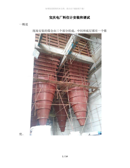
宝庆电厂料位计安装和调试一概述现场安装的煤仓由三个部分组成,中间和底层都有一个锥度。
因为煤仓的面积比较小,只有4m乘4m的面积,而中间有两个2m乘0.5m的进料口,故可能装在如何一个点受进料的影响都比较大,而雷达安装要求离管壁要1m,故综合考虑把安装点定在下图所标示的地方。
二,安装注意事项1,雷达的抛物线天线必须要伸进煤仓。
经测了煤仓顶部混凝土厚度为11cm,而雷达的安装上法兰到天线末端只有16.2cm,为了使天线更多的伸入煤仓,可以把下法兰嵌入混凝土中。
2雷达天线和法兰的组装如下图。
详细可以参考5600中文手册41页到46页3 电气接线交流电源,接X1接线盒,零线接3号端子,火线接4号端子。
上位机接X2接线盒,1号端子接正,2号端子接负。
4 软件组态截图5 手操器组态菜单常用的设置用黄色标注。
详细的请参考英文手册108页。
主要参数1 Antenna type(天线类型)---Parabolic(抛物面天线)2 Tank type(罐体类型)---Cubical tank(立方罐)Tank high (罐高)--雷达法兰面到测量最底部距离3 Tank bottom type(罐底类型)----Cone(锥型)4 Tank Environment(罐体环境)---Solid product(固体产品)5 Output(输出)--upper range value (20mA对应液位)--lower range value (4mA对应液位)6 upper null zone(上盲区)--最好设为1m7 General Thresold(门限值)--最好设为100mV8 Alarm Mode(仪表报警模式)---freeze Current(冻结最近测量值)三.关于罐高的设定我们知道,我们在使用雷达作为过程生产料位测量的目的是:保证在过程生产中被测量料位不出现冒罐(仓),不空罐(仓)。
所以,在使用非接雷达作为带锥形体罐(仓)的料位测量中,根据我们的应用经验和实际情况及成功的许多案例,我们建议:锥形体部分不作为测量,把测量的零点往上移到垂直体部分,只测量垂直体部分的料位。
- 1、下载文档前请自行甄别文档内容的完整性,平台不提供额外的编辑、内容补充、找答案等附加服务。
- 2、"仅部分预览"的文档,不可在线预览部分如存在完整性等问题,可反馈申请退款(可完整预览的文档不适用该条件!)。
- 3、如文档侵犯您的权益,请联系客服反馈,我们会尽快为您处理(人工客服工作时间:9:00-18:30)。
Page1
设置罐高
注意:罐高为法兰表面到罐底实际高度,请 实际测量,并输入到雷达里
[File Name or Event] Emerson Confidential 27-Jun-01, Slide 2
Page2
设置罐高
[File Name or Event] Emerson Confidential 27-Jun-01, Slide 3
Page3
设置罐高
[File Name or Event] Emerson Confidential 27-Jun-01, Slide 4
Page4
ห้องสมุดไป่ตู้
设置罐高
注意:罐高为法兰表面到罐底实际高度,请 实际测量,并输入到雷达里
需要完成图中 的前四项内容。 分别为罐高、 罐体类型、是 否导波管安装 及导波管内径、 罐体管嘴高度
[File Name or Event] Emerson Confidential 27-Jun-01, Slide 5
Page5
设置天线类型(缆绳类型及长度)
[File Name or Event] Emerson Confidential 27-Jun-01, Slide 6
Page6
设置天线类型(缆绳类型及长度)
需要完成图中 的前三项内容。 分别为缆绳类 型、缆绳长度、 上部死区高度
缆绳类型分为:单软缆、单硬缆、双软缆、同 轴等等,请根据实际类型选择;
缆绳长度:从雷达法兰下表面到缆绳末端重锤
上沿;上部死区通常设置为两倍管嘴高度,根
据实际情况适当调整。
[File Name or Event] Emerson Confidential 27-Jun-01, Slide 7
Page7
设置输出量程
[File Name or Event] Emerson Confidential 27-Jun-01, Slide 8
Page8
设置输出量程
[File Name or Event] Emerson Confidential 27-Jun-01, Slide 9
Page9
设置输出量程
Page11
设置输出量程
根据实际测量情况设置仪表量程,注意量程上 限不要进入到上部死区中。设置原则,量程上 限+上部死区,小于等于罐高
[File Name or Event] Emerson Confidential 27-Jun-01, Slide 12
Page12
将图中第一项,更改为Level,表示雷达输出 液位。
[File Name or Event] Emerson Confidential 27-Jun-01, Slide 10
Page10
设置输出量程
[File Name or Event] Emerson Confidential 27-Jun-01, Slide 11