9260-8i卡操作手册
三星手机GT-I9260,GT-I9268如何设置IP拨号
Last Update date : 2013.05.11
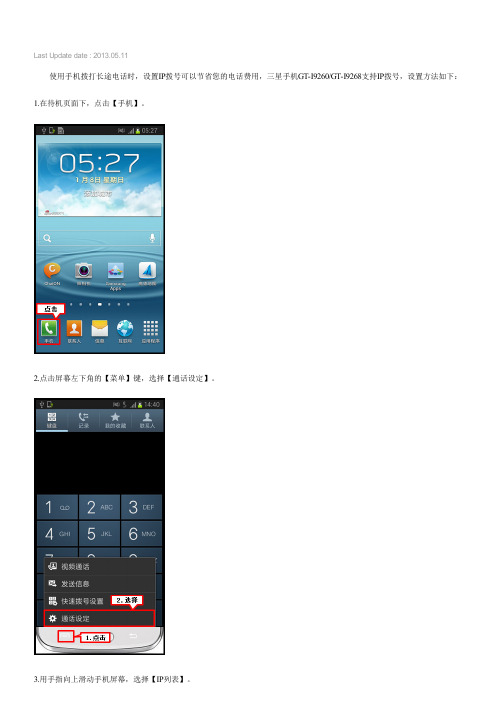
使用手机拨打长途电话时,设置IP拨号可以节省您的电话费用,三星手机GT-I9260/GT-I9268支持IP拨号,设置方法如下:1.在待机页面下,点击【手机】。
2.点击屏幕左下角的【菜单】键,选择【通话设定】。
3.用手指向上滑动手机屏幕,选择【IP列表】。
4.点击屏幕右上方的“+”图标,可添加IP拨号。
(如您想使用的IP号码在列表中有显示,直接选择即可。
)
5.输入需要添加的IP号码,然后点击【储存】。
6.选择设置好的IP号码。
以上设置完成后,您可以通过以下两种方法进行IP拨号:
一、在手机拨号界面进行IP拨号。
1.在待机页面下,点击【手机】。
2.在拨号界面输入联系人号码,然后点击【IP拨号】键即可拨出。
二、在联系人界面进行IP拨号。
1.在待机页面下,点击【联系人】。
2.选择一个联系人。
3.点击【IP通话】即可。
更多内容
三星手机GT-I9260/GT-I9268如何设置短信黑名单?
三星手机GT-I9260/GT-I9268如何删除短信黑名单号码?三星手机GT-I9260/GT-I9268如何设置来电黑名单?
三星手机GT-I9260/GT-I9268如何删除来电黑名单号码?三星手机GT-I9260/GT-I9268如何下载电子邮件中的附件?
相关型号信息
GT-I9260AADCHN ,。
9608 IP电话用户手册

Avaya 对本网站中或 Avaya 提供的文档中引用的任何链接网站的内容 或可靠性概不负责。 Avaya 对于此类网站提供的任何信息、声明或内 容概不负责,因而没有必要对其中描述的信息或提供的产品、服务表示 认可。 Avaya 无法保证这些链接始终有效,也无法控制链接页面的可 用性。
保修
商标
所有其他商标均为其各自所有者的财产。
下载文档
Avaya 在下列许可类型范围内向终端用户提供使用许可证。 除非本文 档或最终用户适用的其他材料指定不同的许可数目或功能单元,否则所 授许可的适用数目及功能单元将为一 (1) 个。 “指定处理器”是指单一 独立的计算设备。 “服务器”指托管可由多个用户访问的软件应用程
防止盗取电讯服务
“盗取电讯服务”指未经授权的一方(例如,非公司员工、代理商、转 包商或不代表贵公司利益的人员)擅自使用您的电讯系统。 请注意, 您的系统会存在与盗取电讯服务相关的危险,如果发生盗取电讯服务, 则将导致电信服务额外费用的明显增加。
Avaya 欺诈投诉
如果您怀疑自己遭遇通讯费方面的欺诈,并需要技术协助或支持,美国 及加拿大用户请致电技术服务中心通讯费方面的欺诈投诉热线 +1-800-643-2353。 其他支持中心电话号码,请查看 Avaya 支持网 站:/support/。 对于 Avaya 产品的可疑安全漏 洞,请通过电子邮件发送至:securityalerts@,向 Avaya 报 告。
以下一个或多个专利涵盖 T9 Text Input 和其它产品:美国 专利 号 5,187,480,5,818,437、5,945,928、5,953,541、6,011,554、 6,286,064、6,307,548、6,307,549 以及 6,636,162,6,646,573、 6,970,599;澳大利亚专利 号 727539、46674、747901;奥地利专利 号 AT225534、AT221222;巴西 P.I. 号 9609807-4;加拿大专利 号 1,331,057、2,227,904,2,278,549、2,302,595;日本专利 号 3532780、3492981;英国专利 号 2238414B;香港标准专利 号 HK1010924;新加坡专利 号 51383、66959、71979;欧洲专利 号 1 010 057 (98903671.0)、1 018 069 (98950708.2);韩国专利 号 KR201211B1、KR226206B1、402252;中国专利 号 ZL96196739.0; 墨西哥专利 号 208141、216023、218409;俄罗斯专利 号 2206118、 2214620、2221268;其它专利申请未决
41216-01_RevA_SAS_9260-4i_8i_DE-8i

Thank you for purchasing the MegaRAID® SAS (Serial Attached SCSI/Serial AT A II) 9260-4i RAID controller, the SAS 9260-8i RAID controller, or the SAS 9260DE-8i RAID controller (PCI-Express).Please take a few minutes to read this quick installation guide before you install your RAID controller. If you need more information about any topic covered in this guide, refer to the related documents on your MegaRAID Universal Software Suite CD.Note:Record your controller serial number in a safe location in case you need to contact LSI.The MegaRAID SAS 9260-4i is a 6Gb/s, PCI-Express, low-profile RAID controller. It controls four internal SAS/SATA ports through one SFF-8087 Mini SAS 4i internal connector. The MegaRAID SAS 9260-8i is a 6Gb/s, PCI-Express, low-profile RAID controller. It controls eight internal SAS/SAT A ports through two SFF-8087 Mini SAS 4i internal connectors. There are two differences between the SAS 9260-4i RAID controller and the SAS 9260-8i RAID controller:–The SAS 9260-4i supports four ports and the SAS 9260-8i supports eight ports–The 9260-4i does not contain the JT7 connector, which is for ports 7–4Note:The SAS 9260DE-8i RAID controller is the same as the SAS 9260-8i RAID controller except thatthe 9260DE-8i RAID controller offers datasecurity through disk encryption.Note:SAT A II is the only type of SAT A supported by these RAID controllers.Y ou can connect the LSI intelligent Battery Backup Unit 07 (LSIiBBU07) directly to these RAID controllers. For more information about this battery, refer to the Intelligent Battery Backup Units for 1078-based MegaRAID Products User’s Guide on the MegaRAID Universal Software Suite CD.R A I D C O N T R O L L E R I N S T A L L A T I O NStep1Unpack the RAID ControllerUnpack the RAID controller in a static-freeenvironment. Remove it from the antistatic bag,and inspect it for damage. If the RAID controllerappears to be damaged, or if the MegaRAIDUniversal Software Suite CD is missing, contactLSI or your MegaRAID OEM supportrepresentative.The CD contains utility programs, device driversfor various operating systems, and the followingdocumentation:•MegaRAID SAS 6Gb/s RAID ControllersUser’s Guide•MegaRAID SAS Software User’s Guide•MegaRAID SAS Device Driver InstallationUser’s Guide•Software license agreementStep2Prepare the ComputerT urn off the computer, and unplug the powercords from the rear of the power supply. Removethe cover from the computer.Step3Review the Jumpers and the ConnectorsFigure1 shows the location of the jumpers andthe connectors on the RAID controller. Thejumpers are set at the factory, and you usually donot need to change them.Back up your data before you change yoursystem configuration. Otherwise, you might losedata.Before you install the RAID controller, make surethat the computer is disconnected from the powerand from any networks.!CAUTION!CAUTIONMegaRAID SAS 9260-4i, SAS 9260-8i, and SAS 9260DE-8i RAID ControllersQuick Installation GuideFigure 1Layout of the MegaRAID SAS 9260-8i/9260DE-8i RAID ControllerT able 1 describes the jumpers and the connectors on the SAS 9260 RAID controllers.Table 1Jumpers and ConnectorsNote:JT1, JT2, and JT4 are behind the LSIiBBU07 when it is installed, but they are still accessible.Step 4Install the RAID ControllerInsert the RAID controller in a PCI Express slot on the motherboard, as shown in Figure 2. Press down gently, but firmly, to seat the card correctly in the slot. Secure the RAID controller to the computer chassis with the bracket screw.Note:This is a PCI Express x8 card and it can operate in x8 or x16 slots. However, some PCI-E slots support only PCI-E graphics cards; if a RAID controller is installed, it will not function. Note:Refer to the guide for your motherboard for information about the PCI Express slot.Jumper/Connector Type DescriptionJT1Write-pending Indi-cator (dirty cache) LED connector 2-pin connector Connects to an LED that indicateswhen the data in the cache has yet to be written to the storagedevices. Used when the write-back feature is enabled.JT2SAS Activity LED header2-pin connectorConnects to an LED that indicates drive activity.JT3Battery Backup connector20-pin connectorConnects the LSIiBBU07 intelli-gent Battery Backup Unit directly to the RAID controller.JT4Global Drive Fault LED header2-pin connector Connects to an LED that indicates whether a drive is in a fault condition.JT6x4 SAS Ports 3–0Mini SAS 4i connector Connects the cables from the con-troller to SAS drives or SATA II drives, or a SAS expander.JT7x4 SAS Ports 7–4Mini SAS 4i connectorConnects the cables from the con-troller to SAS drives or SATA II drives, or a SAS expander.1.The SAS 9260-4i RAID con-troller does not have this con-nector.JT8Modular RAID Key header2-pin connector Reserved for LSI use.JT9Set FactoryDefaults connector2-pin connectorReturns the board settings to the defaults set in the factory.JT10LSI Test header2-pin connector Reserved for LSI use.JT11IPMI-style SMBus (System Manage-ment)/I 2C header3-pin shielded headerProvides enclosure management support.JT12Individual Drive Fault LED headerfor Eight Phys (0-7)16-pin connector Indicates drive faults. There is oneLED per port. When lit, each LED indicates the corresponding drive has failed or is in the Unconfig-ured-Bad state. Refer to theMegaRAID SAS Software User’s Guide for more information.The LEDs function in a direct-attach configuration (there are no SAS expanders). Direct attach is defined as a maximum of one drive connected directly to each port.This header is used for RAID controllers with internal SAS ports.JT13Universal Asyn-chronous Receiver/Transmitter (UART) debugging4-pin connectorReserved for LSI use.Jumper/Connector Type DescriptionFigure2Installing the MegaRAID SAS 9260-8i/ 9260DE-8i RAID ControllerStep5Configure and Install the SAS Devices, SATA II Devices, or Both in the Host Computer CaseRefer to the documentation for the devices for anypreinstallation configuration requirements.Step6Connect the RAID Controller to the SASDevices, SATA II Devices, or Both in the HostComputer CaseUse SAS cables to connect the RAID controller toSAS devices, SATA II devices, or both. SeeFigure1 to view the connector locations.Refer to the MegaRAID 6Gb/s SAS RAIDControllers User’s Guide on the MegaRAIDUniversal Software Suite CD for detailedinformation about the SAS cables.Step7Turn on the Power to the ComputerReinstall the computer cover, and reconnect thepower cords. Turn on the power to the computer.Make sure that the power is turned on to the SASdevices and the SATA II devices before or at thesame time that the power to the host computer isturned on. If the power is turned on to thecomputer before it is turned on to the devices, thecomputer might not recognize the devices.The firmware takes several seconds to initialize.During this time, the controller scans the ports. Step8Run the WebBIOS Configuration UtilityRun the WebBIOS Configuration Utility toconfigure the groups and the virtual drives. Whenthe message Press<Ctrl><H> for WebBIOSappears on the screen, immediately pressCTRL+H to run the utility.Note:Refer to the MegaRAID SAS Software User’s Guide on the MegaRAID Universal SoftwareSuite CD for detailed steps on configuring groupsand virtual drives.Step9Install the Operating System DriverThe RAID controller can operate under variousoperating systems, but you must install thesoftware drivers first.The MegaRAID Universal Software Suite CDincludes the software drivers for the supportedoperating systems, along with documentation.Y ou can view the supported operating systemsand download the latest drivers for RAIDcontrollers from the LSI website at:/cm/DownloadSearch.do.Access the download center, and follow the stepsto download the driver.Refer to the MegaRAID SAS Device DriverInstallation User’s Guide on the MegaRAIDUniversal Software Suite CD for more informationabout installing the driver. Be sure to use thelatest service packs that are provided by theoperating system manufacturer and to review thereadme file that accompanies the driver.S U P P O R T E D R A I D L E V E L SThe RAID controllers support drive groups using the following RAID levels:•RAID 0 (data striping): Data is striped across all drives in the group, enabling very fast data throughput. There is no data redundancy. All data is lost if any drive fails.•RAID 1 (drive mirroring): Data is written simultaneously to both drives in the drive group, providing complete data redundancy if one drive fails. RAID 1 supports an even number of drives from 2 to 32 in a single span.•RAID 5 (drive striping with distributed parity): Data is striped across all drives in the group. Part of the capacity of each drive stores parity information that reconstructs data if a drive fails. RAID 5 provides good data throughput for applications with high read request rates.•RAID 6(drive striping with distributed parity across two drives): Data is striped across all drives in the group and two parity drives are used to provide protectionagainst the failure of up to two drives. In each row of data blocks, two sets of parity data are stored.•RAID 00: RAID 00 is a spanned drive group that createsa striped set from a series of RAID 0 drive groups.41216-01 Rev. A, July 2009Find a list of LSI Corporation’s U.S. distributors, international distributors, sales LSI, the LSI logo design, and MyStorage are trademarks or registered trademarks of LSI Corporation. All other brand and product names may be trademarks of their respective companies.Copyright © 2009 by LSI Corporation. All rights reserved.LSI Corporation reserves the right to make changes to any products and services herein at any time without notice. LSI does not assume any responsibility or liability arising out of the application or use of any product or service described herein, except as expressly agreed to in writing by LSI; nor does the purchase, lease, or•RAID 10 (RAID 1 and RAID 0 in spanned groups): RAID 10 uses mirrored pairs of drives to provide complete data redundancy. RAID 10 provides high data throughput rates.•RAID 50 (RAID 5 and RAID 0 in spanned groups): RAID 50 uses both parity and drive striping acrossmultiple drives to provide complete data redundancy.RAID 50 provides high data throughput rates.•RAID 60 (RAID 6 and RAID 0 in spanned groups): RAID 60 uses both distributed parity across two parity drives and drive striping across multiple drives to provide complete data redundancy and high fault tolerance. Note:Refer to the MegaRAID SAS Software User’s Guide on the MegaRAID Universal SoftwareSuite CD for more information about RAID levels.T E C H N I C A L S U P P O R TFor assistance in installing, configuring, or running your SAS 9260-4i, 9260-8i, or 9260DE-8i RAID controller, contact your LSI Technical Support representative. Click the following link to access the LSI T echnical Support page for storage and board support:/support/storage/tech_support/index.html From this page, you can send an email, call Technical Support, or submit a new service request and view its status. E-mail:/support/support_form.htmlPhone Support:/support/storage/phone_tech_support/ index.html1-800-633-4545 (North America)00-800-5745-6442 (International)Note:The international toll-free number does notrequire country specific access codes.。
LSI 9260用户手册

用户手册MEGA RAID WEB1、按F2进入BIOS,将Quiet Boot :设置为[Disabled],保存后重启。
根据提示按<Ctrl>+<H>进入WEB 主菜单2、按回车《Enter》或者点接《start》进入卡的主菜单如图3,右边显示9个主菜单,左边显示所有硬盘的信息。
点接Configuration Wizard(配置向导)选择New configuration 配置新的RAID两个选项,手动创建和自动创建,这里选择手动创建,下一步按住《Ctrl》键用鼠标选择你需要的硬盘,然后点接Add to Array(添加到阵列)Accept DG(接受磁盘阵列)—>点接Next(下一步)点击Add to SPAN点击下一步在RAID Level(RAID级别)处选择你需要的RAID,这里以RAID5为例,,在Select Size (选择输入容量),输入208854。
右边分别显示出RAID 0 、RAID10 、RAID5 、RAID 6的容量,相应的RAID 级别输入右边对应的容量。
然后点接 Accept(接受)—>点接Next(下一步)我这里选择了透写(Write Pplicy:Write Through,drive Cache所以下一步的时候会多出两步,一般加缓存电池的时候才选,不然有丢缓存的危险选择YES下一步接受按YES保存配置选择初始化类型,GO初始化会清空硬盘里边的数据,选择YES,阵列做完了选择HOME ,回到主菜单,右边的框会多出来逻辑卷删除阵列点接Configuration Wizard(配置向导)选择Clear configuration 下一步选择YES,阵列删除完成修复(Rebuild)阵列如果RAID5阵列中有一个硬盘掉线或者坏,这时阵列卡会发出报警声,进RAID卡界面后你会看到右边物理驱动器下面显示红色,Virtual Drives(虚拟驱动器)下面VD0显示Degraded(降级状态),在机器上找到对应的硬盘盘位,拔下坏的硬盘,换上新硬盘后,阵列会自动修复(Rebuild),如果换上的新硬盘里面的有数据,阵列不会自动修复,那就要把这个硬盘做成热备(HotSpare),下面介绍热备的做法首先得保证有一好的硬盘没有被配置成阵列或者热备,下图以500G硬盘为例点击未配置的硬盘,如果硬盘里没有数据直接就是图二,如果硬盘里有数据那就是图一那个界面出现图一:选择上Make Unconf Good(使未知的硬盘变好)—>点接Go(继续)就到了图二出现图二:选择上 Make Glocal HSP(使这个硬盘为全球的热备),然后点接Go(继续)—图一图二:点击HOME回到主菜单,热备做好了!硬盘状态由未配置变成Hotspare,,如果有硬盘故障,热备盘就会自动顶上去,变成Rebuilding状态,等修复完成之后,阵列卡报警声音消失。
Lsi 9260-8i阵列卡操作手册(简版)

Lsi9260-8i阵列卡操作手册目录:一、如何进入RAID卡BIOS界面二、BIOS主界面三、创建阵列四、如何创建与删除热备盘五、删除阵列一、如何进入RAID卡BIOS 界面阵列卡信息按下组合键进入BIOS界面1、开机到此界面时按下组合键Ctrl+H进入RAID卡BIOS 管理界面。
二、WebBIOS主界面0、Advanced Software Options高级软件选项1、Controller Selection选择RAID卡(机器上安装有多张RAID卡时)2、Controller Properties RAID卡属性设置3、Scan Devices刷新硬盘设备4、Virtual Drives虚拟磁盘管理5、Drives物理硬盘管理6、Configuration Wizard创建阵列配置7、Logical View/Physical View查看逻辑/物理磁盘(点击切换)8、Events事件9、Exit退出三、创建阵列1、查看物理硬盘在界面右面可看到可用于组建RAID 的硬盘○1Slot :0——硬盘的物理位置,在0号端口。
○2Unconfigured Good ——好的,未配置的硬盘。
2、点击“Configuration Wizard ”进入创建阵列配置,如图:○1Clear Configuration 清除所有的阵列配置信息○2New Configuration 新建RAID 配置(会清除所有的数据,一般只在新机器第一次做阵列时选择)○3Add Configuration 增加RAID 配置3、一般选择Add Configuration ,按Nex t 进入下一步进入Select Configuration Method 界面:12○1Manual Configuration 手动配置○2Automatic Configuration 自动配置以下先以WD 2TB*4组建RAID10为例:3、选Manual Configuration 手动配置进入下一步:○1在左边“Drives ”框中选择要做RAID 的磁盘,按住Ctrl 键可一次同时选择多个。
常用操作系统安装指南-R680G7

第四章常用操作系统安装指南注意:1.以下安装指南适合于用户不采用万全导航操作系统安装导航盘进行自动安装的情况;若用户使用万全导航操作系统安装导航盘自动安装操作系统,请参照《联想万全服务器万全导航用户手册》中操作系统安装部分进行。
2.安装操作系统之前,请务必先阅读操作系统安装前的准备工作说明,确认您的机型配置,做好必需的驱动备份,然后参照对应的安装指南进行操作。
3.请您准备一台运行主流Windows中文版操作系统的机器,将万全导航驱动程序光盘放入光驱中,按提示信息找到所需的驱动程序,并根据提示信息将驱动程序备份到联想USB闪存式软盘驱动器(Lenovo USB Floppy Driver Key)。
4.驱动程序备份的详细操作方法,请参见《联想万全服务器万全导航用户手册》相关内容。
5.如果您配置的硬盘有效总容量大于2T,请参考本手册第五章相关内容。
说明:本指南以板载SATA RAID配置为例进行操作系统安装说明,其它配置操作系统安装方法类似。
4.1 此安装指南适用LSI 8708E/LSI 9260-8i配置包含以下常用的操作系统安装指南:1.Windows Server 2003 Enterprise Edition R2 SP2 x86简体中文版2.Windows Server 2003 Enterprise Edition R2 SP2 x86英文版3.Windows Server 2003 Enterprise Edition R2 SP2 x64简体中文版4.Windows Server 2003 Enterprise Edition R2 SP2 x64英文版5.Windows Server 2008 R2 Standard Edition x64简体中文版6.Windows Server 2008 R2 Enterprise Edition x64简体中文版7.Windows Server 2008 R2 Standard Edition x64英文版8.Windows Server 2008 R2 Enterprise Edition x64英文版9.Windows Server 2008 R2 Standard Edition x64 OEM简体中文版10.Windows Server 2008 R2 Enterprise Edition x64 OEM简体中文版11.RedHat Enterprise Linux AS 5.0 Update 4 x8612.RedHat Enterprise Linux AS 5.0 Update 4 x6413.Suse Linux Enterprise Server 11 x8614.Suse Linux Enterprise Server 11 x6415.Suse Linux Enterprise Server 10 SP2 X8616.Suse Linux Enterprise Server 10 SP2 X644.1.1 Windows Server 2003 R2SP2简体中文版安装指南说明:本节适用于以下几种操作系统:1.Windows Server 2003 Enterprise Edition R2 SP2 x86简体中文版2.Windows Server 2003 Enterprise Edition R2 SP2x64简体中文版一、安装前的准备工作参照导航软件的使用说明,从导航光盘上把安装Windows Server 2003所需的LSI 8708E或LSI 9260-8i驱动程序备份到联想USB闪存式软盘驱动器(Lenovo USB Floppy Driver Key,以下简称USB Key)。
MC9260-EK 硬件资源使用手册

目 录1、概述 (3)2、测试程序使用说明 (3)2.1、网络接口测试 (3)2.2、UART测试 (4)2.3、CAN测试 (4)2.4、USB Host测试 (5)2.5、MMC/SD测试 (6)2.6、BUZZER测试 (6)2.7、LED测试 (6)2.8、AUDIO测试 (6)2.9、RTC测试 (7)2.10、ADC测试 (7)2.11、矩阵键盘测试 (8)1、概述MC9260的光盘EXP目录下附带了几个接口的测试程序,这些测试程序是关于这些接口的基本应用,用户可以用某种存储媒体(U 盘、SD 卡、网络)拷到板上的 Linux 系统下面运行下面部分是关于这些测试程序的使用说明;如果要更了解这些测试程序的具体情况,请查看源代码。
2、测试程序使用说明2.1、网络接口测试将主板的网络接口用直连网线与路由器、交换机连接或者交叉线与PC机连接,可以测试主板的网络。
主板启动完成后,设置主板IP与PC机同一网段,测试与主机连接。
添加网关,ping迈冲科技网址测试。
2.2、UART测试MC9260 有7个串口,对应如下:tyS0――DEBUGttyS1――COM1 ttyS2――COM2 ttyS3――COM3ttyS4――COM4 ttyS5――COM5 ttyS6――COM6选择相应串口和 PC机的串口连接,在 PC机上运行一个串口的终端,设置如下:z115200 Bits per Secondz8 Data Bitsz No Parityz 1 Stop Bitsz No Flow Control运行 uart_test,手动输入所选的串口和工作模式,在 PC 机的终端输入字符,如"any data of type",回车后,其余串口测试一样,只是要注意输入串口序号与实际串口的对应关系。
说明:工作模式1:自动接收测试串口数据并按原数据回发工作模式2:手动输入数据并从测试串口发送,自动接收串口数据2.3、CAN测试CAN接口测试一般需要两个CAN设备连接起来才能正常通信,如果用户只有一块开发板,则可以用回环模式进行测试。
raid卡使用说明书
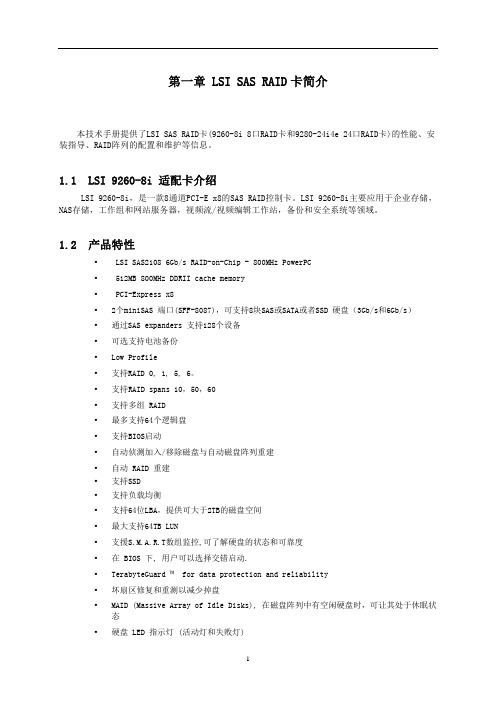
第一章 LSI SAS RAID卡简介本技术手册提供了LSI SAS RAID卡(9260-8i 8口RAID卡和9280-24i4e 24口RAID卡)的性能、安装指导、RAID阵列的配置和维护等信息。
1.1 LSI 9260-8i 适配卡介绍LSI 9260-8i,是一款8通道PCI-E x8的SAS RAID控制卡。
LSI 9260-8i主要应用于企业存储,NAS存储,工作组和网站服务器,视频流/视频编辑工作站,备份和安全系统等领域。
1.2 产品特性• LSI SAS2108 6Gb/s RAID-on-Chip - 800MHz PowerPC• 512MB 800MHz DDRII cache memory•PCI-Express x8•2个miniSAS 端口(SFF-8087),可支持8块SAS或SATA或者SSD 硬盘(3Gb/s和6Gb/s)•通过SAS expanders 支持128个设备•可选支持电池备份•Low Profile•支持RAID 0, 1, 5, 6。
•支持RAID spans 10,50,60•支持多组 RAID•最多支持64个逻辑盘•支持BIOS启动•自动侦测加入/移除磁盘与自动磁盘阵列重建•自动 RAID 重建•支持SSD•支持负载均衡•支持64位LBA,提供可大于2TB的磁盘空间•最大支持64TB LUN•支援S.M.A.R.T数组监控,可了解硬盘的状态和可靠度•在 BIOS 下, 用户可以选择交错启动.•TerabyteGuard ™ for data protection and reliability•坏扇区修复和重测以减少掉盘•MAID (Massive Array of Idle Disks), 在磁盘阵列中有空闲硬盘时,可让其处于休眠状态•硬盘 LED 指示灯 (活动灯和失败灯)•Email 通知•SNMP 远程管理•警报器提示硬盘状态/阵列状态•Enclosure Management 支持 SES 和 SPGIO•Intelli-VRM™ (Intelligent Virtual RAID Management)•在线扩容 (OCE) 和在线RAID迁移(OLRM)•提供快速以及后台初始化,使磁盘阵列可以立刻使用•支持直写和回写•Web GUI RAID 管理工具 (local and remote monitoring)•SHI (Drive analysis driven from S.M.A.R.T)•Windows (2000, XP, x64, 2003, 2008,2008R2, Vista (32 and 64Bit), Linux (Fedora Core, Red Hat Enterprise / CentOS, SuSE), Mac OS X 10.4.x and above,FreeBSD , Linux Open Source1.3 RAID概念及术语在描述LSI 9260-8i适配卡的时候经常用到以下概念和术语。
- 1、下载文档前请自行甄别文档内容的完整性,平台不提供额外的编辑、内容补充、找答案等附加服务。
- 2、"仅部分预览"的文档,不可在线预览部分如存在完整性等问题,可反馈申请退款(可完整预览的文档不适用该条件!)。
- 3、如文档侵犯您的权益,请联系客服反馈,我们会尽快为您处理(人工客服工作时间:9:00-18:30)。
4024RAID卡使用手册本册主要介绍RAID卡常用功能,raid的创建,参数配置及管理软件的介绍下面先从开机启动时如何进入管理界面开始介绍1.当机器开启后,显示器出现阵列卡检测信息时,会提示用户是否要进入管理界面对阵列卡进行操作,此时按下Ctrl+H即可,如下图1图12.按下Ctrl+H后,进入控制器选择界面,若只有一张卡,便如下图2所示,多张卡会分行显示,选择相应的控制器后,按start进入管理界面图23.若出现图3所示:Foreign Config(s) Found.则说明当前使用的硬盘存在之前使用的raid设定信息。
若要重新导入raid设定,可点击Preciew尝试;对于正常新建raid,请直接点击clear 进入下一步图34.此时,会出现提示窗,如图4,告知当前的操作会清除掉硬盘上之前的所有raid配置信息,是否要继续,请直接点击yes进入下一步:图45.图5所示为RAID卡的WebBIOS管理界面,左侧边栏为功能设定选项,右侧部分会显示阵列和磁盘的相关状态信息。
图56.新建raid时,请点击左侧Configuration Wizard选项,进行相关操作。
如图6Raid配置向导,点击可创建Raid图67.点击Configuration Wizard后,会出现下图7所示界面,提示选择相关操作,A:Clear Configuration 选择此项后,可清除已经存在的raid 设定B:New Configuration 选择此项后, 清除已经存在的raid设定,并可继续进行新的Raid配置。
C: Add Configuration 选择此项后,可新建Raid,对已经存在的Raid不会有任何影响。
通常情况下,Clear Configuration用于清除阵列卡上所有的已经存在的阵列信息,一旦进行,所有的Raid信息都不存在。
而Clear Configuration选项一般为客户首次进行Raid设定,此时阵列卡上一般不存在阵列。
Add Configuration选项用于阵列卡已经存在有Raid设定了,而使用者想新增其他Raid来满足使用要求时使用的,对已经存在的Raid不会有影响。
图78.以选择Add Configuration为例,点击next后,就会出现图8所示,选择配置模式,手动设置还是自动设定,一般选择默认手动设定继续进行。
图89.图9所示为阵列创建选项,左侧Drivers选项,显示了所有可正常使用的磁盘,右侧为磁盘组信息。
图910.选择左侧的相应硬盘后,点击下方的Add To Array 即将一块磁盘添加到Drivergroup里,已完成的设定会显示绿色。
(按下Ctrl键同时点击硬盘,可以实现一次添加多个磁盘)图1011.添加完成后,点击右侧Drivergroup栏下的Accept DG即完成一个磁盘组DG的设定,(DG 所含磁盘的数量多少决定了Raid的级别,Raid 0至少要求1块磁盘,Raid 1至少要求2块磁盘Raid 5至少要求3块磁盘)如图11图1112.若将不同容量的硬盘添加在同一Driver Group内,会以最小的磁盘容量为准进行raid配置,点击Next进行下一步时,会出现警告提示,如图12,点击OK即可进入下一步操作。
图1213.图13所示为Span添加界面,完成Span添加后才能进行Raid创建,将左侧的Array with FreeSpace下的DG选中,点击Add to SPAN即可完成添加。
图1314.添加完成SPAN后,会在右侧Span栏显示,点击Next进入下一步设定。
如图14图1415.图15所示为Virtual Driver配置:——RAID Level:从下拉列表中选择可选的RAID级别。
如RAID0,RAID5等。
——Strip Size:条带化大小定义了RAID配置中每个硬盘的数据块的大小。
建议选择默认大小64K。
—— Access Policy:选择数据访问的类型,主要包含:1) RW,允许读写操作。
这是默认值。
2) Read Only(只读),允许只读操作。
3) Blocked(禁止):不允许访问。
——Read Policy:指定虚拟驱动器的读取机制,主要包含:1) Normal :此选项禁用预读机制。
这是默认值。
2) Ahead:此选项启动预读机制。
允许控制器提前顺序读取所需数据并且和其他数据一起存储在缓存中。
这将提高顺序数据的读取速度,但是对读取随即数据的性能没有明显提升。
——write Policy :指定虚拟驱动器的写操作机制,主要包含:1) Write Through:即直写模式。
这是默认设置,性能非常低。
2) Always Write Back:即回写模式,设置为此模即使用RAID卡CACHE,性能优。
3) Write Back BBU:如果控制器没有电池(BBU)或电池(BBU)故障,但仍想使用回写模式,则选用此选项。
如果不选用此选项,当控制器检测到没有电池(BBU)或电池(BBU)损坏时,将自动切换至直写模式(WThru)。
——IO Policy :此选项允许读取一个特定的虚拟驱动器(Virtual disk)。
不影响预读(read ahead)缓存。
1) Direct :该模式下读取的数据不在缓存中缓冲。
而且直接从缓存传输的主机。
如果相同的数据被再次读取,则直接从缓存读取。
这是默认值。
2) Cached :该模式下,所有读取的数据都要在缓存中缓冲。
——Drive Cache :指定驱动器缓存的机制。
1) Enable :启动硬盘驱动器的缓存。
2) Disable :关闭硬盘驱动器的缓存。
这是默认值。
3) Unchanged :保持现有的驱动器缓存机制不做改变。
——Disable BGI:指定后台初始化(Background initialization)状态:1) No :保持后台初始化启动。
这是指新的配置设定会在后台进行初始化并且此时可以使用WebBIOS进行其他的设置。
这是默认值。
2) Yes :这项表示禁用后台初始化(Background initialization)。
——Select Size :指定虚拟驱动器(Virtual disk)的大小,以GB为单位。
通常,这个值是该磁盘组RAID级别的最大容量。
Virtual disks栏下面会显示相关RAID的最大容量。
图1516. 点击Accept按钮,接受对虚拟驱动器(Virtual disk)的配置更改。
或者点击Reclaim按钮返回到之前的设置。
如图16,为点击Accept按钮后的界面,在Virtual Drivers下面的空白栏会出现绿色的VD0图1617.点击Next按钮,结束对虚拟驱动器(Virtual disk)的配置。
此时会显示虚拟驱动器虚拟驱动器(Virtual disk)的信息,如图17图1718. 如果虚拟驱动器(Virtual disk)的配置信息无误,点击Accept按钮保存配置信息。
否则,可以点击Cancel按钮来结束该操作并返回到WebBIOS的主界面。
或者,点击Back 按钮返回到上一个界面,更改配置信息。
i如果配置接受之前的配置信息,在弹出确认2次保存的提示时,点击Yes按钮,保存配置。
19 确认之后,会显示初始化主界面如图18。
可选择相应初始化类型,完成后即可。
至此,raid创建全部结束。
(Riad0,Riad1,Riad5,Riad6)图1820.以下步骤介绍下如何配置RAID10, RAID50, RAID60图19a. 如图19所示,左侧窗口显示物理驱动器(Physical Drivers)列表,可以按下<CTRL>键同时选中两个或多个处于Ready状态的物理驱动器用来创建第一个磁盘组(Disk Group)。
b. 点击右侧窗口下的Accept DG选项,将选中的物理硬盘移动至右侧磁盘组(DiskGroups)中的第一个磁盘组。
如果需要撤销以上操作,可以点击Reclaim按钮。
c. 左侧窗口显示物理驱动器(Physical Drivers)列表,可以按下<CTRL>键同时选中两个或多个处于Ready状态的物理驱动器用来创建第二个磁盘组(Disk Group)。
(注:两个磁盘组必须配置相同)d. 点击右侧窗口下的Accept DG选项,将选中的物理硬盘移动至右侧磁盘组(Disk Groups)中的第二个磁盘组。
如果需要撤销以上操作,可以点击Reclaim按钮。
e. 结束选择硬盘步骤之后,点击Next。
会进入设置扩展阵列的屏幕。
如下图20所示:图20f. 在屏幕上左侧的窗口中显示Array With Free Space选项,按住<CTRL>选择一个磁盘组(Disk Group),然后点击Add to SPAN。
已经选中的磁盘组(Disk Group)会显示在右边的Span窗口。
g. 按下<CTRL>键同时选中第二个磁盘组(Disk Group),然后按Add to SPAN按钮。
然后所选中的磁盘组(Disk Groups)会显示在右边的Span窗口中。
如图21图21h. 点击Next按钮。
会进入设置虚拟驱动器(Virtual disk)属性的页面。
如前面描述,可以做详细参数的设置。
具体参数和之前设定一样,只是RAID级别会变了,这里就不在说明了。
如图22图2221.若RAID发生异常可在webios主界面Logical View里面显示出相关信息如图23所示,RAID5中有一块硬盘坏掉,找不到磁盘,Driver显示SLOT1插槽物理盘丢失,RAID5降级。
图2322.此时插入一块新的物理磁盘(不能含有raid信息)系统会自动修复重建,如图24图24。