星河尚品移动电源产品手册-PPT(可编辑)
移动电源商品说明书解读
移动电源商品说明书解读移动电源是一种便携式充电设备,可以为我们的手机、平板电脑和其他电子设备提供电力支持。
本文将对移动电源商品说明书进行解读,帮助用户更好地理解和使用移动电源。
1. 产品介绍移动电源是一种以锂电池为能量储存单元的充电设备,具有便携性和高容量的特点。
它采用先进的充电和放电技术,可为各类数码产品提供稳定、可靠的电力支持。
同时,移动电源还配备了多个充电接口,兼容不同品牌和型号的设备,为用户提供更加便捷的充电体验。
2. 使用注意事项(1)在初次使用移动电源之前,请先阅读本说明书并仔细阅读产品标签上的警告和提示信息。
(2)请勿将移动电源暴露在高温环境中,例如阳光直射或火源附近。
(3)请勿将移动电源投入水中或进行湿手操作,以免发生短路等安全问题。
(4)请使用原配充电器或通过合适的接口进行充电,避免使用低质量或不合适的充电设备,以免损坏移动电源。
(5)请勿将移动电源长时间连续充电或放电,以免对电池寿命产生不良影响。
建议定期进行充放电循环,保持电池性能。
(6)使用移动电源时,请勿任意拆卸或修改设备,以免导致安全隐患。
3. 充电说明(1)使用标配充电器或合适的充电线将移动电源连接到电源插座,待指示灯亮起表示充电开始。
(2)充电过程中,指示灯将保持稳定亮起,当电池充满时,指示灯将熄灭或变为绿色。
(3)充电过程中,移动电源可能会有轻微的发热现象,属于正常现象,无需过分担忧。
4. 输出电流和充电速度移动电源的输出电流和充电速度将取决于接入设备的功率需求和接口规格。
为了最大程度地满足用户需求,我们的移动电源在设计上做了充分考虑,提供了不同输出端口和相应的最大输出电流。
例如,对于普通手机充电,我们的移动电源通常支持至少2.4A的输出电流,以确保快速而稳定的充电效果。
5. 多重保护措施为了确保用户的安全和移动电源的正常工作,我们的产品内置了多种保护机制,包括过压保护、过流保护、短路保护和温度保护等。
当移动电源检测到异常情况时,会自动切断供电,以保护用户设备和电池的安全。
移动电源使用说明书
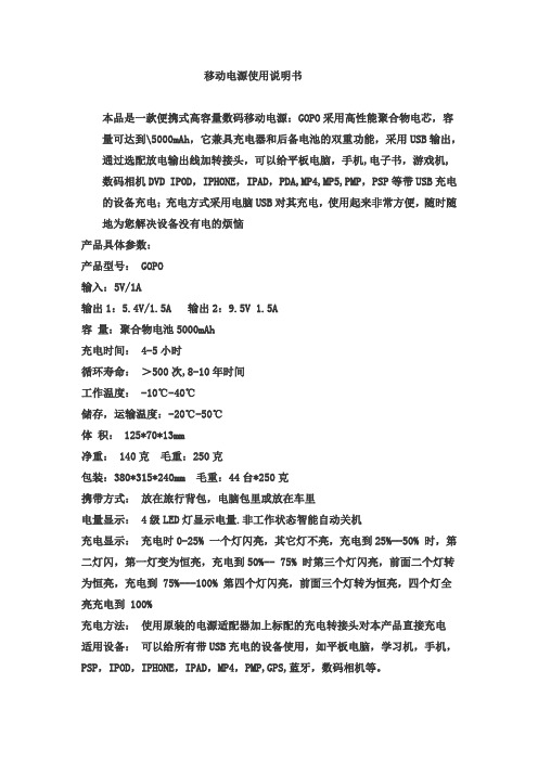
移动电源使用说明书本品是一款便携式高容量数码移动电源:GOPO采用高性能聚合物电芯,容量可达到\5000mAh,它兼具充电器和后备电池的双重功能,采用USB输出,通过选配放电输出线加转接头,可以给平板电脑,手机,电子书,游戏机,数码相机DVD IPOD,IPHONE,IPAD,PDA,MP4,MP5,PMP,PSP等带USB充电的设备充电;充电方式采用电脑USB对其充电,使用起来非常方便,随时随地为您解决设备没有电的烦恼产品具体参数:产品型号: GOPO输入:5V/1A输出1:5.4V/1.5A 输出2:9.5V 1.5A容量:聚合物电池5000mAh充电时间: 4-5小时循环寿命:>500次,8-10年时间工作温度: -10℃-40℃储存,运输温度:-20℃-50℃体积: 125*70*13mm净重: 140克毛重:250克包装:380*315*240mm 毛重:44台*250克携带方式:放在旅行背包,电脑包里或放在车里电量显示: 4级LED灯显示电量.非工作状态智能自动关机充电显示:充电时0-25% 一个灯闪亮,其它灯不亮,充电到25%--50% 时,第二灯闪,第一灯变为恒亮,充电到50%-- 75% 时第三个灯闪亮,前面二个灯转为恒亮,充电到 75%---100% 第四个灯闪亮,前面三个灯转为恒亮,四个灯全亮充电到 100%充电方法:使用原装的电源适配器加上标配的充电转接头对本产品直接充电适用设备:可以给所有带USB充电的设备使用,如平板电脑,学习机,手机,PSP,IPOD,IPHONE,IPAD,MP4,PMP,GPS,蓝牙,数码相机等。
操作使用方便1.选好与数码产品相对应的电压2.选好要用的数码产品对应的转换头3.将选好的转换头插入你所用的数码产品上4.精确显示电池电量5.超长使用寿命6.无记忆效益7.超长循环次数。
可达500多次循环。
即使到达500多次以后仍可保证80%以上的电量8.具有安全可靠性9.本产品采用国际领先科技的进口锂电池,具有环保,安全,无毒危险10.智能自动短路保护设计,所有接座均具有短路保护功能注意事项1.请勿将输出电压调整到高于设备电压,否则有可能引起设备损坏,请在使用前一定确认清楚2.请使用指定充电器3.禁止短路,分解和抛入火中4.不得擅自拆卸充电器和电池对其进行改造5.注意防潮防水Mobile power supply manualThis product is a portable high-capacity digital mobile power: GOPO high-performance polymer batteries, the capacity can be achieved \ 5000mAh, which combines the dual function of the charger and battery backup, using the USB output, through the optional discharge the output line. computer USB charging adapter, charge; charging mode to tablet PCs, mobile phones, e-books, game consoles, digital cameras, DVD IPOD, IPHONE, IPAD, PDAs, MP4, MP5, the PMP, PSP and other devices with USB charging , very convenient to use anywhere, anytime to solve your equipment without electricity troublesSpecific parameters:Product Model: GOPOInput: 5V/1AOutput 1:5.4 V/1.5A output 2:9.5 V-1.5ACapacity: Polymer battery 5000mAhCharging time: 4-5 hoursCycle life:> 500 8-10 yearsOperating temperature: -10 ℃-40 ℃Storage and transport temperature: -20 ℃-50 ℃Dimensions: 125 * 70 * 13mmNet weight: 140 g Gross Weight: 250 gPackaging: 380 * 315 * 240mm GW: 44 units * 250 gCarrying methods: on the travel bag, computer bag, or in the carPower display: four LED lights to display power. Non-working status of the intelligent automatic shutdownCharge: charging 0-25% of a light shining, the other lamp is not lit, charging to 25% - 50%, the second light flash, the first light into constant light, the charge to 50% - 75% when the third light flashes in front of two light became lit, charging to 75% --- 100% the fourth light flashes in front of three lights became lit, four full bright light to charge to 100 % Charging method: using the original power adapter with standard charging adapter direct charge of the productApplicable devices: all devices with USB charging, machine learning, such as tablet PCs, mobile phones, the PSP, IPOD, IPHONE, iPad, MP4, PMPs, GPS, Bluetooth, digital cameras and so on.Easy to operateSelecting the voltage corresponding to the digital productsSelected to use digital products corresponding to the conversion head3 will be selected adapter into your digital productsAccurately display the battery power(5) Long life6. Memory efficiencyLong cycle times. Up to 500 cycles. Even reached 500 beyond, to ensure that more than 80% of electricity8 with the safety and reliabilityThis leading international technology imported lithium batteries, environmentally friendly, safe, non-toxic hazardsThe intelligent automatic short circuit protection design, all access seat are short circuit protectedNoteDo not output voltage adjusted to higher than the voltage of the device, or they may cause damage to the equipment, please be sure that before usingPlease use the specified chargerProhibit short circuit, decomposition, and into the fire(4) shall not disassemble charger and battery to transformNote that the moisture waterproof移动电源怎么用拥有了移动电源,就会开始使用移动电源。
移动电源培训讲义(PPT 29张)

聚合物电池
聚合物电池的优点:体积小巧,重量轻,使用寿命长,绿色环保,绝对不会爆炸。缺点:因为是科技新产品,目前是价格相对来说高企,随着工艺的
开放,这类型电池的价格会降下来,逐步取代普通锂电芯。
羽博 移动电源 王国
名 称
型 号
容 量
配
件
长 征 长 征 烈 日 旭 日 皓 月 皓 月 便 携 便 携 续 航 背 夹 背 夹
c、移动电源应处于干燥环境中。雨水、湿气和各种液体或水分会腐蚀电子元件和线路。
d、移动电源不能存放在高温处。高温将缩短电子装置的寿命 、损坏电池并使某些塑料老化。 e、不能用粗暴的使用方式扔掷、敲击移动电源。粗暴的使用方式可能会损坏内部电路板及精密机械。 f、移动电源的电芯和移动电源质量有直接关系。在购买移动电源的时候不要贪小便宜去购买劣质移动电源. 目前主目前主导品牌有:明能、立派、ONSO、长虹能量仓、YOOBAO、品胜、清华紫光、爱国者动力舱、威正科技、Anymay、超牌、劲量、电小二、川 宇、安能、哈里通、海能源等。
YOOBAO移动电源手册
品 质 改 变 生 活
目 录
羽博 移动电源 发展史
移动电源的发展史
概念:
移动电源,也叫“外挂电池”、“外置电池”、 “后备电池”、“数码充电伴侣”、“充电棒”、
“充电棍”,移动电源概念是随着目前数码产品
的普及和快速增长而发展起来的,其定义就是方
便易携带的大容量随身电源。目前数码产品功能
移动电源的发展史
注意事项:
使用移动电源产品,还需注意几个问题 : a、移动电源的输出电压须在5±0.5V的范围内,否则不能给某些品牌手机充电; b、中转接头一定要匹配,移动电源产品的使用原理是通过USB连接线给数码设备充电的,连接线带USB接口的一端连接移动电源产品,而另一端接数 码设备,因此另一端的接口就必须跟数码设备的接口一致,否则无法充电。另外USB线内阻不能过大,超出正常标准会造成充电时间过长甚至充电失 败。
AA胶电池可移动电源产品说明书

Energy Management System Operation ManualPlease read this manual before attempting to install or operate any of theEMS system components. AA Portable Power Corp. will not be responsiblefor any problem due to misusing.Catalogue1Introduction: (3)2Specification (3)3Typical diagram: (4)4Heart Beat LED (5)5Isolate Battery & Shunt connection: (6)612V Power: (6)7Monitor Page select switch: (7)8Sense Board Wiring: (7)9Battery balancing (9)10Video Output (10)11Can Bus Output (Optional) (10)12Main Screen: (11)13Individual Cell Page (12)14Alarms: (13)15Controlling Devices with Alarm Outputs (14)16Capacity Algorithm (14)17Ground Fault Detection (15)18Trouble Shooting (16)1Introduction:Thank you for purchasing Energy Management System (EMS). This manual covers the operating and installation information for this systemThe EMS system has everything needed to display the condition and maintain the health of lithium ion batteries and is specifically designed to work with GBS Lithium Ion batteries.The system consists of two major components, the computer Master (MASTER) and the cell sense boards. The MASTER shows details about the condition of the battery pack, such as current, voltage, state of charge and individual cell details, via its video output display. The sense boards form a simple daisy chain by mounting on each cell to read voltage and temperature; they also perform battery balancing during recharging to equalize the charge within the battery pack. Two alarm outputs, one for over voltage and one for under voltage, provide automatic shut off signals to prevent overcharging or over discharging of the battery pack. A unique feature of the EMS system is ground fault detection. High voltage systems should be floating relative to the chassis for safety. If an inadvertent path to the chassis ground is made the system will detect it and display a warning for this unsafe condition. The EMS outputs composite video to display battery pack information. A CAN (controller area network) interface option is available to output the information from the EMS to other systems.2Specificationoutputs3Typical diagram:The EMS is designed to make installation as easy as possible. All of the connections to it are made with convenient pluggable ¼” quick disconnect terminals. The EMS Master should be installed as close to the shunt as possible. The shunt sense wires should be less than 1’ long. A mounting template for the computer is shown in Appendix A. After the installation is complete, the battery pack must be completely charged before the capacity will read correctly (see Section 7.Capacity Algorithm for more details).Note: The EMS system components utilize either a conformal coating or rubberized coating on all components to allow them to perform in high humidity environments. They are not however water proof. All components must be installed inside water resistant containers.4Heart Beat LEDWhen the EMS is correctly connected to 12V, the heartbeat indicator will blink once per second5Isolate Battery & Shunt connection:The Terminals on the left side of the Master are used for making the High-Voltage and shunt connections. Refer to the figure below for these connections. The connections between the battery pack, shunt and high voltage loads are usually large wire (e.g. 2/0 depending on the max current of the system).The connections to the EMS from the battery and the shunt can be smaller gauge (e.g. 18 or 20 Awg).Note: Please use extreme caution when making these connections as the full battery pack potential will be present between the shunt and battery pack positive pins. Connecting these wires incorrectly can cause damage to the EMS MASTER which will not be covered under warranty.The wires connecting to the shunt should be a twisted pair or wires with as short of a distance from the MASTER as possible to achieve accurate measurements.612V Power:The MASTER is powered by 12 volt s, which is connected to the terminals marked “12V”and “GND”. This should be connected to a power source through a 5A fuse. The power can either be always on, or can be switched off to conserve power. 12 volt power must besupplied at any time when the battery pack is being charged or discharged. When 12 volt power is applied the red heartbeat LED will blink.If the battery pack is more than a 12 volt battery, and the MASTER is to be powered off of it,a DC/DC converter must be used so that the battery pack is discharged equally. Under nocircumstances can four cells within the battery pack be tapped for 12 volt power for the MASTER as this will cause an imbalance within the battery pack.Note: T here are three pins marked “GND” for ground on the MASTER. These three pins are common together. Only one of these pins needs to be connected, the other two are located for convenient connection options. It is not chassis.7Monitor Page select switch:To change the display on the MASTER to the individual cell screen(s) a normally open momentary switch is used to short the pins marked (MDE) to (GND). There is no polarity to the switch and the connection can be small gauge wire (e.g. 18 Awg). In applications where the 12 volt power is grounded to a vehicle chassis only one wire needs to be ran from the MDE pin and can be grounded to the chassis through the momentary switch.8Sense Board Wiring:The sense boards are connected to the MASTER via a cable with five pins. Depending on which sense board version the system was supplied with this cable will have either four or five wires connected to it. This connector has a retention mechanism. If removal of this cable is needed never pull in the wires, always pull up on the connector, to avoid damage to the wire harnessThe MASTER will automatically index the sense boards based on their position in the daisy chain of sense boards. The first sense board connected to the MASTER will be cell number one and will count up from there. It is recommended that the negative most cell in the pack be made cell number one and have the daisy chain move toward the most positive cell in the pack. This will aide in troubleshooting if needed; however, the sense boards can be connected in any order.Before installing sense boards, install all cell jumpers first with the outer two screws tightened. Never install sense boards underneath jumpers as this will cause current to flow through the screws, which is a poor connection. Never slide a jumper underneath a sense board while installing as this may cause a short with components which are located on the back of the sense board.When installing sense boards, keep cell covers installed on all cells except the cell where the sense board is being installed. Do not allow sense boards to lie on battery terminals. This will help prevent accidental damage to sense boards during installation.The sense boards have an input and an output connector. Before installing, ensure that they are oriented in the appropriate direction. The male connector is the input; the female connector is the output.The sense boards have battery positive and negative indicated on them. Ensure that the polarity is correct before installing. The boards will not be damaged by a reverse polarity; however, they will not function. When a sense board is installed correctly the green LED will light up. There is also a red LED on the sense board, which indicates cell balancing is occurring.This led will light up any time the cell voltage is 3.55V or higher.Note: The sense boards, like the cells they attach to, alternate + and – for the series connection. The last string in the daisy chain is not terminated and will have its output connector not connected to anything. Should the installation have less than an even multiple of 4 cells, the cable may be cut close to the last sense board used. Be sure to cut the cable cleanly with no wires left exposed. Do not cut the cable with 12V power applied to the MASTER! The resulting short circuit may damage the EMS computer.9Battery balancingWhen the battery voltage rises during charging to 3.55V or above the red balancing LED will light on the sense board to indicate the cell is balancing. The sense boards will draw 0.5A until the voltage has dropped below 3.55V. It is normal for some cells to balancemore than others and some cells to rarely balance.10 Video OutputThe EMS MASTER outputs composite video output through a common RCA type jack. This can be connected to the optional LCD screen EPS provides or any other display which will accept this type of input (e.g. in dash DVD). The video cable is not provided as length requirements vary. A shielded cable is recommended if there is snow or static in the video signal11 Can Bus Output (Optional)If your MASTER has the optional CAN bus interface this connector will be on the side of the MASTER.12 Main Screen:When properly installed, the EMS system will display the Voltage, current, capacity and alarm status of a Lithium Ion battery pack. This is an example of what the main screendisplays:Number of Cells is indicated at the top of the screen as “E.M.S –x” where x is the number of sense boards the MASTER has been programmed to manage. If the system detects a value other than this it will trigger an unmanaged cell alarm.Battery Pack Voltage is the total battery pack voltage. This updates in real time and the numerical value is displayed below the bar. This bar will be green whenever voltage is between 3.0V x N (the number of cells in the pack). When the voltage drops below 3.0V x N the bar will turn red to indicate low voltage. The bar will also turn red when the voltage rises over 3.4V x N to indicate that the target charging voltage range has been attained. If the voltage goes outside of the range of the bar and off scale message will appear.Battery Pack Current is the current either being drawn from the battery or being recharged into it. Like the voltage bar this is indicated in real time and the numerical value is displayed below the bar. This bar will be green and will turn red when current is above 200A. When current is negative and the battery is being charged this bar will turn white and “Charging” will be displayed.Battery Pack Capacity is the battery state of charge. It works by tracking the amount of charge that goes in and out of the battery pack. It will reset to 100% during charging when the current is within a normal charging range for a battery charger and the total battery pack voltage reaches 3.52 x N (the number of cells). When the system is powered up for the first time this value will read 50%. The battery will have to be charged to full in order to reset the capacity reading correctly to 100% the first time.Min/Max Cell Voltage provides a quick overview of the maximum and minimum cell voltages within the battery pack. Depending on the number of cells within the battery pack, these values update every 1 -2 seconds.Alarms and Warnings are displayed at the bottom of the screen after the word “Pack:”.There are seven alarms:- Over voltage (highest cell is over 3.8V after a 3 second delay)- Under voltage (lowest cell is below 2.8V after a 30 second delay)- Over current (current exceeds 10C for 10 seconds)- Over temperature (highest cell exceeds 150°F or 65°C)- Under temperature (lowest cell is below 32°F or 0°C, charging is not allowed)- Ground fault (There is a high voltage leakage greater than 2mA to the chassis pin)- Unmanaged cells (The programmed number of cells does not equal the number of cells read)13Individual Cell PageTo access the individual cell detail page(s) refer to section 7, Page Select Switch Input.When momentary switch is pressed and released it will change the display to show the first20 cells in the pack with details of voltage and temperature of each cell as shown below:If there are more than 20 cells in the pack pressing the button again will advance tothe next 20 cells until the last cell page is reached, then pressing the button againwill return to the main screen.Cell (number) is the location of the sense board relative to the daisy chain of sense boards. The cell connected to the MASTER first is number one.Volts is the actual cell voltage. This updates every 1-2 seconds, depending onthe number of cells in the pack.Temp is the temperature reading. This updates every 1-2 seconds, depending on the number of cells in the pack. The number will turn red if the cell exceeds the upper temperature limit. Readings are in °F by default; however, upon request, this can be set to read in °C.The cell temperature is measured at the positive terminal of each sense board. If a single cell has noticeably higher temperature during use than other cells, but the temperature goes back down quickly this may be an indication of a poor connection where there is high contact impedance. Also, during balancing the temperature will temporarily rise due to the energy being converted to heat.Note that this screen will not automatically update if more or less cells are connected during installation. To update the screen the Page Select buttonmust be pressed until it has cycled back through the main screen, then back tothe individual cell detail screens in order to update the view. Cell voltage and temperatures are updated in real time on these screens.14Alarms:In order to protect the battery pack there are a number of alarms, which are based on cell voltage, temperature and pack current and fault conditions. The MASTER contains two alarm output pins, UV for under voltage and OV for over voltage. When any of the alarm conditions are met for a specified duration of time they will activate their respective action listed in the table below:The alarm limit values may vary with special request configurations.The same delay time must elapse once an alarm condition is cleared to deactivatethe alarm.15Controlling Devices with Alarm OutputsThe alarm outputs on the MASTER output 12 volts and can drive continuously 2A with up to a 4A surge. Exceeding these limits or short circuiting these pins may cause damage to the MASTER. The alarms act according to the above table. It is very important that these alarm outputs be able to disconnect the battery pack from loads and charging sources when they activate; this must be a no parasitic load condition to fully protect the battery. Ensure that items such as controller pre- charge resistors, DC/DC converters, lights, etc. are all disconnected in the event that the low voltage alarm triggers. Failure to properly implement these alarm interlocks may void the warranty on the battery.When all parameters are within normal ranges these alarm outputs will be 12 volts. They will drop to 0 volts during an alarm condition. When power to the MASTER is removed these outputs will not supply power. Systems should be designed such that they require power from the alarm outputs from the MASTER in order to function.16Capacity AlgorithmThe EMS MASTER keeps track of the capacity of the battery pack by tracking current in and out of the battery (coulomb counting). There are however several corrections built in to the software to ensure that the capacity stays accurate over time.The capacity will reset to 100% if the following conditions are met:- Total pack voltage measures 3.52V x N (N being the number of cells) when being charged by a battery charger.The capacity will reset to 100% if the following conditions are met:- The over voltage alarm is triggered when being charged by a battery charger, see default alarm table for set points.The capacity will reset to 0% if the following conditions are met:- The under voltage alarm is triggered and discharging current is not excessive, see default alarm table for set points.When the EMS is powered up the first time the capacity will read 50%, which is approximately the state of charge that the batteries ship at when new. To sync the capacity the first time the battery pack must be charged full, which will trigger a reset to 100%.The capacity measurement is done based on the programming in the MASTER. MASTER’s cannot be interchanged with one which has been programmed for a different battery pack configuration.Upon special request the MASTER can be programmed to extend battery life by limiting the depth of discharge to 80%. This will scale the capacity bar such that 100% of the scale is 80% of the battery capacity. Once the capacity reaches 0%, which is 20% of the actual capacity remaining, the under voltage (UV) output will automatically shut off.17Ground Fault DetectionThe pin marked “Chassis” is used for the ground fault detection circuitry integrated in to the EMS MASTER. This should be connected to its own dedicated chassisground point. When this is done and the shunt and battery positive wires areconnected properly the system will be able to detect a ground fault anywhere within the battery pack. This feature will display an alarm message on the screen if there is a fault condition, but will not cause any alarm actions to be taken. If this message appears there is a potentially dangerous ground fault condition which should be corrected.The alarm will be triggered any time a current of 2mA or greater is detected from the battery pack to the chassis pin.If the EMS system is being used on a lower voltage system (<50 volts) where the battery pack is grounded to the chassis, this wire should not be installed to disable this feature. EPS does not recommend grounding battery packs in excess of 12 cells in series for safety.When performing work on a high voltage battery pack, the Chassis pin should temporarily be disconnected as it will induce a very small, non-dangerous, current to the chassis which could cause small electrical shocks.18Trouble ShootingA sense board is reporting a temperature above the spec limit and is shutting down the system to protect the batteryCheck for loose connectionsA sense board is reporting a temperature below the spec limit for charging and has shut off charging equipment to protect the battery packA potentially dangerous leakage current to the chassis has occurred. Find the source of this leakage and remove it.For low voltage systems where the battery pack is grounded to the chassis disconnect this pin to eliminate this feature.。
移动电源2S说明书修改版
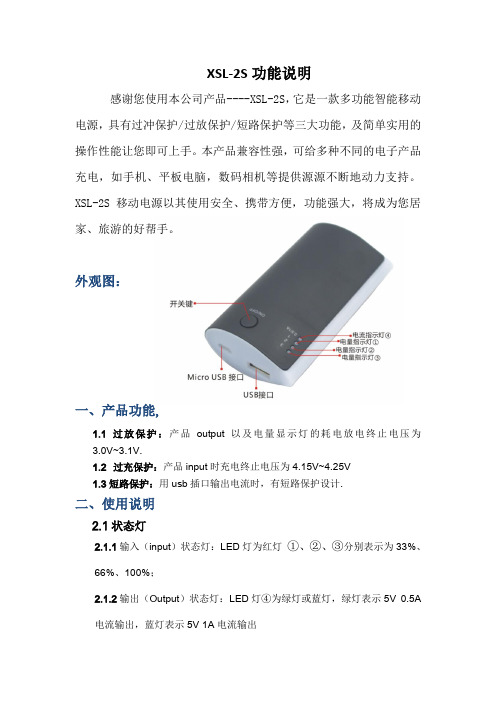
XSL-2S功能说明感谢您使用本公司产品----XSL-2S,它是一款多功能智能移动电源,具有过冲保护/过放保护/短路保护等三大功能,及简单实用的操作性能让您即可上手。
本产品兼容性强,可给多种不同的电子产品充电,如手机、平板电脑,数码相机等提供源源不断地动力支持。
XSL-2S移动电源以其使用安全、携带方便,功能强大,将成为您居家、旅游的好帮手。
外观图:一、产品功能,1.1过放保护:产品output以及电量显示灯的耗电放电终止电压为3.0V~3.1V.1.2过充保护:产品input时充电终止电压为4.15V~4.25V1.3短路保护:用usb插口输出电流时,有短路保护设计.二、使用说明2.1状态灯2.1.1输入(input)状态灯:LED灯为红灯①、②、③分别表示为33%、66%、100%;2.1.2输出(Output)状态灯:LED灯④为绿灯或蓝灯,绿灯表示5V 0.5A电流输出,蓝灯表示5V 1A电流输出2.2输入(input)连接AC与产品micro USB口2.2.1输入电流控制在1A,接通电流后,红色LED灯闪烁显示充电状态,充满后,三个电量显示灯保持长亮,直至将断开电源后方才熄灭;2.2.2输入(Input)过程中,不可同时输出电流对手机充电,此时操作开关按键无效,对输入无影响。
2.3输出(output)连接产品USB接口与手机:2.3.1在对电子产品进行充电时,需先通过开关键预设充电电流(5V/0.5A,5V/1A或5V/2A),再接通USB线对电子产品开始充电,在充电过程中,充电电流不可更改,若要更改需拔出USB线后重新设定;2.3.2电流传输过程中按下开关键可查看产品剩余电量,亮灯色为红色,从左到右①、②、③分别表示为33%、66%、100%,所显示电量LED灯亮起两秒钟后熄灭,当产品接近无电状态时,①灯闪烁;output灯保持一直长亮,同时充电电流亦保持不变;2.3.3 output过程中不可以同时进行input,如有电流通过min usb插口流入则output停止,进入input状态;2.3.4如连接线发生短路,产品马上切断电流,output灯熄灭,三个电量显示灯一起闪烁(不按产品剩余电量标示),此现象为短路保护显示,5秒后自动关闭所有LED;2.4 其他功能2.4.1开关按键:控制output时电量显示灯以及output输出状态2.4.2照明功能:长按住开关键照明灯亮,同时电量显示灯持续点亮两秒钟后熄灭。
移动电源讲义

移动电源的电芯比较
Question: PN-906用的是什么电芯? 尺寸: 76×58×21mm 淘宝价:99-120元/pcs 三个18650并联 (根据18650的容量、PN-906的尺寸及价 格判断)
奥娜美发展有限公司 Original Beauty Development Co., Ltd.
移动电源的参数选项聚合物锂电18650锂电容量100018000mah转换率60708090电源控制方案硬件方案单片机方案输出电流500ma800ma1a2a充电和放电剩余电量指示led显示移动电源本身充电时间输入电流6小时之内为宜充满截止精度假设截止电压42v1的误差将带来416和424的区别而424v将造成电池寿命损伤好的充电电路是可以自动停充截止精度高于05的过流短路防过充防过放保护pcb方案自耗电充满后存30天余电达50辅助功能手电筒移动存储收音机音箱能充电次数400500相关的物理公式奥娜美发展有限公司originalbeautydevelopmentco
奥娜美发展有限公司 Original Beauty Development Co., Ltd.
相关的物理公式 U=RI P=UI W=PT=UIT 1瓦(1W)=1焦/秒(1J/s)=1伏· 安(1V· A)
奥娜美发展有限公司 Original Beauty Development Co., Ltd.
左图的规格: PN-906 3.7V/5600mAh 21Wh Input:5V 1A Output:5V 1A 76×58×21mm
奥娜美发展有限公司 Original Beauty Development Co., Ltd.
锂电池电压 1) 3.7V/5600mAh 21Wh 3.7-4.2V 锂电池电压 3.7V是指电池电用完时的最低电压 4.2V是电池充电的最高限制电压
移动电源产品知识

3、移动电源方案分类
⑴ 、硬件方案
硬件:是指IC厂家把程序写好封存在一个IC里面,而且里面的程序是不能更改的, 厂家编写这颗IC有什么功能,它就只有所编写的那些功能。如:英集芯的IP5306等, F118、F168、F169等都是用的英集芯的IP5306。所以我们这些产品用的就是硬件方案。
硬件方案的优势: 原厂供货、线路简单、效率高(90%以上)、性价比高。再者市 面流通量大,经过市场的考验,性能和品质有保障。
大家都知道,水在管中所以能流动,是因为有着高水位和低水位之间的差别而产生的一 种压力,水才能从高处流向低处。城市中使用的自来水,所以能够一打开水门,就能 从管中流出来,也是因为自来水的贮水塔比地面高,或者是由于用水泵推动水产生 压力差的缘故。电也是如此,电流所以能够在导线中流动,也是因为在电流中有着 高电位和低电位之间的差别。这种差别叫电位差,也叫电压。换句话说。在电路中, 任意两点之间的电位差称为这两点的电压。
缺点:温度偏高,IC程序不可修改。
⑵软件方案:
软件:指的是IC厂家只编写这颗IC程序的大致框架,内部的细节需要自己去编写, 可以根据客户的需求,在IC里面任意的编写程序,修改程序。如:SF015、Z855、P5 等。
软件的优势:温度低,可以根据客户的需求来编写程序。
缺点:在升压输出方面,MCU是用软件实现PWM控制,普通的MCU频率相对较低, 做出来的效率也稍显偏低(85%)、线路复杂、价格偏高。
过压保护电压是6V左右,智融(SW6106)的过压保护电压是13V左右)达到某一个 电压值时,就会关闭输入电压,从而起到保护原件不被高电压烧坏。 ⑷、输入过充保护: 输入标准范围:4.2V 当移动电源电芯的电压达到4.2V时,输入电流为零(因电压与电流为共生关系, 电压是电流的载体,只要两者的任一者为零时,就会停止工作)。
移动电源产品介绍 ppt课件
PPT课件
29
21
消费需求分析
对移动电源产品概念和功能认识在逐步加强,男性对产品了解多于女性。
PPT课件
22
1、 客户群体:年轻,有活力,热爱电子数码产品 的时尚人群
2、移动电源使用环境:普遍用于旅游或商旅等不方 便直充的情况下,为保持数码或电子产品的正常 使用,提供简单方便快速的充电。
PPT课件
23
理性消费者购买心理诉求:
PPT课件
1
移动电源
PPT课件
2
目录
店铺介绍 移动电源项目介绍 产品宣传片
PPT课件
3
PPT课件
4
PPT课件
5
PPT课件
6
PPT课件
7
PPT课件
8
成功提交等待审核
PPT课件
9
PPT课件
10
主要产品
PPT课件
11
P-3500移动电源的原理是:220V交流电通过 适配器转化成DC5V电压给内置的容量为 3500mA/h的锂电池充电(充电时间约7个小 时),然后在通过控制电路将内置3.7V锂电池升 到5.5V通过输出口给Iphone、手机、数码相机、 MP3、MP4等数码产品充电,适用于出差、旅游、 长途乘车船、野外作业等环境的备用电源。
1、高端产品(具有权威性和公认性) 2、功能(主功能满足所需、细节突破、方 便好用)
3、品质(质量保证、安全环保) 4、视觉感满意(外形设计时尚有质感) 5、价格(合理、实惠)
PPT课件
24
产品宣传
主题
轻松出行,乐享百变时尚生活
PPT课件
25
PPT课件
26
PPT课件
27