pgx_wireless_ch_ug舒尔话筒
shure kSM11无线话筒拾音头用户指南 (中文)说明书
KSM11无线话筒拾音头Online user guide for KSM11.Version: 1.0 (2022-D)Table of ContentsKSM11 无线话筒拾音头3简要说明3特性3设置和兼容性3型号类别3附件与配件3可选配附件 4可替换配件 4规格4认证6安全事项7有限保修7 FOR ORIGINAL PURCHASES IN AUSTRALIA ONLY 8服务中心 8中国 RoHS9••••••KSM11无线话筒拾音头简要说明Shure KSM11 无线人声话筒拾音头经过专门优化,在现代数字无线现场声音制作过程中,可以更加精准的保护和呈现艺术家的人声。
随着过渡到更全面地融合数字技术的阶段,Shure 充分利用由此实现的线性度提升及控制增强,开发出 KSM11。
KSM11 采用高级心形指向性电容式设计,通过专业手段将换能器和防震架技术结合起来,提供了近乎完美的离轴抑制和非常稳定的指向性响应。
这款产品实现了中低频清晰度和必不可少的高品质细节的完美融合及无缝衔接,专为备受欢迎的无线应用而设计,包括现场表演、现场活动录制和优质流媒体传输。
特性受专利保护的无线电容拾音头配备 3/4 英寸镀金振膜和高品质电子装置,实现出色的动态范围和瞬态响应。
极其稳定的深度心形指向性拾音模式可降低离轴相位失真,从而再现纯净音质,提供饱满而醇厚的低频音质,线性而通透的中频音质以及自然的高品质细节。
流线型设计使拾音头更加轻便小巧。
采用先进的悬浮式隔振系统,基本上实现零触摸杂音。
防凹陷硬化钢制网罩具有三段式爆破音防噗功能,可提供稳定且真实的音质。
可选黑色或拉绒镀镍漆面,配合兼容的 Shure 手持式发射机使用。
设置和兼容性若要使用 KSM11 话筒拾音头,请将其固定在兼容的无线发射机或有线手柄上。
KSM11 与所有 Shure 手持式发射机兼容,配备可移动式拾音头。
另外,KSM11 也与 Shure VPH 有线手柄 XLR 配件兼容,可用于常见的 XLR 连接。
舒尔 ULXD 单套无线麦克风系统 用户指南 Shure ULXD Single wireless

ULX-D无线话筒系统User guide for Shure ULXD Single wireless system. Includes setup instructions, specifications, and troubleshooting. Version: 1 (2019-G)Table of ContentsULX-D无线话筒系统4重要安全事项! 4警告 5重要产品信息5许可信息 5澳大利亚无线警告 5快速入门说明5简要说明6特性 7硬件接口8接收机 8发射机11界面和鹅颈底座发射器 13发射机高级功能 14菜单屏幕 15调节接收机显示亮度和对比度 17主屏幕显示选项 17编辑接收机频道名 18设置区域电视格式 18锁定控件和设置 18电池19电池运行时间表 19 Shure SB900 充电电池 20 Shure SB900 运行时间 20舒尔充电电池保养和存储的重要提示 20安装电池触点盖 20音频21设置接收机增益 21将接收机频道音频输出设置为静音 21发射机输入削波 22音频信号加密 22扫描和同步23多系统设置 24手动频率选择 25发射机红外预设 25建立系统预设值 25射频26发射机射频功率 26干扰检测 26高级射频 26接收机连网27自动 IP 地址分配 27手动 IP 寻址功能 27设备标识 27高密度模式 27系统复位28固件28固件版本 28更新接收机 28更新发射机 29使用 Shure 软件管理您的系统29故障排除29电源 29增益 29线缆 30界面锁定 30加密不匹配 30无线电射频 (RF) 30附件31提供的附件 31选配附件 33规格34接收机输出电平 35表格和示意图 35电池 36频率范围和发射机输出功率 36欧洲国家/地区频率38认证43 Information to the user 441.2.3.4.5.6.7.8.9.10.11.12.13.14.15.16.17.18.19.20.21.ULX-D无线话筒系统重要安全事项!必须阅读这些注意事项。
Shure PGX Wireless Quick Setup说明书

PGX -- Shure PGX Wireless Quick SetupSystem ComponentsAll systems include:•PGX4 receiver• 2 AA batteries•PS24 Power Supply•User guideLavalier, Headworn, and Instrument systems include:•PGX1 bodypack transmitter•Microphone (choice of WL93, WL185, PG30 or Beta 98H/C™)Vocalist systems include:®®•Microphone Head (choice of PG58, SM58, SM86, Beta 58A)•PGX2 handheld transmitter•Microphone clipGuitar systems include:•PGX1 bodypack transmitter•1/4” to mini 4-pin guitar cablePGX4 Receiver FeaturesFront Panel① audio LEDIndicates strength of incoming audio signal: green for normal, amber for strong and red for clipping.② LED ScreenDisplays group and channel setting. See “Single System Setup” for details.③ channel buttonChanges group and channel setting. See “Single System Setup” for details.④ ready LEDIndicates system ready and receiving an RF signal from the transmitter.⑤ Infrared (IR) portSends IR signal to transmitter for sync.⑥ sync buttonPress to synchronize transmitter with receiver group and channel settings.Back Panel⑦ AC adapter jack⑧ Adapter cord tie-off⑨ XLR microphone output jack⑩ 6.35 mm (1/4”) instrument level output jack (unbalanced).Transmitter Controls and Connectors① Indicator LED Displays battery level, mute, and IR transmission status (see table).② Power / Mute Switch Press to mute or unmute. Press and hold to power on or off.③ Infrared (IR) port Receives infrared beam to synchronize frequencies. When using multiple systems, only one transmitter IR port should be exposed at a time.④ 4-Pin Microphone Input Jack.⑤ Audio Gain Adjustment.Transmitter Indicator LEDGreen ReadyFlashing green Controls LockedAmber Mute OnFlashing red IR transmission in processGlowing red Battery power lowPulsing Red on startup Batteries dead (transmitter cannot be turned on untilbatteries are changed)Pulsing Red after synchronization Transmitter and receive incompatible; contact yourShure resellerChanging Batteries•Expected life for an Alkaline battery is approximately 8 hours.•When the transmitter light glows red, the batteries should be changed immediately, as shown. Wearing the Bodypack TransmitterClip the transmitter to a belt or slide a guitar strap through the transmitter clip as shown.For best results, slide the transmitter until the belt is pressed against the base of the clip.Adjusting GainPGX1Three gain settings are available on the PGX1. Choose the appropriate setting for your instrument.•mic: Microphone (higher amplification)•0: Guitar with passive pickups (medium amplification)•–10: Guitar with active pickups (lower amplification)If the receiver LED indicates the input volume is overloading the receiver, try switching the gain to a lower setting. PGX2Access the gain adjustment switch by unscrewing the head of the microphone.Two gain settings are available on the PGX2. Use the tip of a pen or a small screwdriver to move the switch.•0dB: For quiet to normal vocal performance.•–10dB: Use only if audio is distorted due to high voal levels.Single System Setup1 ScanUse the scan feature on the receiver to find a clear channel.a LED screen displays current channelb press channel button to scan for a clear channelc system scans for the channel with the least interference2 SynchronizeSynchronize the transmitter to the receiver by aligning the infrared (IR) ports and pressing the sync button. Make sure the IR ports are closely aligned.After a successful sync, the transmitter LED momentarily flashes red and the receiver ready light illuminates.Multiple System SetupUse the following steps to ensure the best performance when installing multiple wireless systems at the same lo-cation.1.Turn all receivers on and all transmitters off.Note: Turn on any other digital equipment that could cause interference during the performance so it will be de-tected during the frequency scans in the following steps.2.Make sure the group number is the same for all receivers (see Manual Group Selection).3.Perform a scan using the first receiver.4.Turn on the first transmitter and sync it to the receiver.5.Repeat for each system.◦Important: After syncing each transmitter, leave it on so that scans from the other receivers will not select that channel.◦Be sure only one transmitter IR port is exposed when synchronizing each system.Manual Channel and Group Selection (receiver only)Using the receiver to scan for a channel is the best way to find the best frequency for your system. However, for multiple system setup, you may need to manually set the group number.1.Press and hold the channel button.2.Hold the button until the channel or group display begins flashing.3.Release and press the button again to advance the setting. At the desired channel or group number, wait forthe flashing to stop. This activates the new setting.4.Transfer the new frequency setting to the transmitter using the automatic sync function.Locking and Unlocking ControlsLocking the system controls prevents accidental muting or channel adjustment during performances.TransmitterTo lock the controls: With the transmitter off, hold the power button down until the green LED flashes (~5 seconds)To unlock the controls: With the transmitter on, hold the power button down until the green LED flashes (~5 sec-onds)ReceiverTo lock the channel: Hold the channel button until the numbers flash (~10 seconds)To unlock the channel: Hold the channel button until the numbers flash (~5 seconds) TroubleshootingIssue Indicator Status SolutionNo sound or faint sound Transmitter powerlight on, receiverLEDs on•Perform automat-ic transmitter set-up•Verify all soundsystem connec-tionsReceiver LED off•Make sure ACadapter is securlyplugged into elec-trical outlet•Make sure ACelectrical outletworks and is sup-plying propervoltageTransmitter power light glowing or flashing red •Replace transmit-ter batteries•If indicator contin-ues flashing red after batteries are replaced, the transmitter and receiver may be-long to incompati-ble frequency bands. Contact your Shure re-seller for assis-tance.Transmitter power light off •Turn on transmit-ter•Make sure the +/- indicators on bat-teries match the transmitter termi-nals•Insert fresh bat-teriesDistortion or un-wanted noise bursts N/A•Remove nearbysources of RF in-terferance (CDplayers, comput-ers, digital ef-fects, in-ear mon-itor systems, etc.)•‣ Change receiv-er and transmitterto a different fre-quency•‣ Reduce trans-mitter gain•‣ Replace trans-mitter batteries•‣ If using multiplesystems, changethe frequency ofone of the activesystemsDistortion increases gradually Transmitter powerlight glowing orflashing redReplace transmitterbatteriesSound level different from cabled guitar or microphone or when using different guitarsAdjust transmitter gain as necessaryCannot turn trans-mitter onTransmitter light flashing red Replace transmitter batteriesSpecificationsWorking RangeLine of Sight 100 m (300 ft ) Audio Frequency Response45–15000 Hz Total Harmonic DistortionRef. ±33 kHz deviation with 1 kHz tone 0.5%, typicalDynamic Range>100 dB , A-weightedOperating Temperature Range-18°C (0°F)–+50°C (122°F)[3]Transmitter Audio PolarityPositive pressure on microphone diaphragm (or positive voltage applied to tip of WA302 phone plug) produces positive voltage on pin 2 (with respect to pin 3 of low-impedance output) and the tip of the high impedance 1/4-inch output.Note: Actual range depends on RF power setting, signal absorption, reflection, and interference.Note: Dependent on microphone type[1][2]Note: Battery characteristics may limit this range.Audio Input Levelgain positionmic-10 dBV maximum+10 dBV maximum+20 dBV maximumGain Adjustment Range30 dBInput Impedance1 MΩRF Output Power[1]10–30 mWPin AssignmentsTA4M connector1ground(cable shield)2+ 5 V Bias3audio4Tied through active load to ground (On instrument adapter cable, pin 4 floats)Dimensions108 mm x 64 mm x 19 mm (H x W x D)Weight81 g (3oz.), without batteriesHousingMolded Polycarbonate CasePower Requirements2 "AA" size alkaline or rechargeable batteriesBattery Lifeup to 8 hours (alkaline)varies by regionAudio Input Level-10 dB+2 dBV maximum0 dB-8 dBV maximumGain Adjustment Range10 dBRF Output Power[1]10–30 mWDimensions254 mm x 51 mm dia. (10 x 12 in.)Weight81 g (10.2 oz.), without batteriesHousingMolded PC/ABS handle and battery cupPower Requirements2 "AA" size alkaline or rechargeable batteriesBattery Lifeup to 8 hours (alkaline)varies by regionFrequency Range and Transmitter Output Level Band Range Output Power H6524–542 MHz30 mWJ6572.250–590.875 MHz30 mWK5E606–630 MHz10 mWL5644–662 MHz30 mWP6702.200–719 MHz30 mWR1800–820 MHz20 mWBand Range Output PowerT1846–865 MHz10 mWQ8740–752 MHz10 mWJB806–810 MHz10 mWR14794–806 MHz20 mWX5925–932 MHz10 mWG4470.125–493.825 MHz30 mWG8494.200–509.825 MHz30 mWQ24736–754 MHz30 mWThis Radio equipment is intended for use in musical professional entertainment and similar applications. This Ra-dio apparatus may be capable of operating on some frequencies not authorized in your region. Please contact your national authority to obtain information on authorized frequencies and RF power levels for wireless micro-phone products.Frequency Range and Transmitter Output PowerBand Frequency Range (MHz)Power ( mW RMS )* (Lo/Nm/Hi)G50470 to 534 1 / 10 G51470 to 534 1 / 10 G52479 to 534 1 / 10 G62510 to 530 1 / 10 H50534 to 598 1 / 10 H51534 to 598 1 / 10 H52534 to 565 1 / 10 H53534 to 598 1 / 10 J50572 to 636 1 / 10Band Frequency Range (MHz)Power ( mW RMS )* (Lo/Nm/Hi)J51572 to 636 1 / 10JB806 to 810 1 / 10K51606 to 670 1 / 10K52606 to 670 1 / 10L50632 to 696 1 / 10L51632 to 696 1 / 10L52632 to 694 1 / 10L53632 to 714 1 / 10P51710 to 782 1 / 10P52710 to 782 1 / 10Q51794 to 806 1 / 10S50(823 to 832) (863 to 865) 1 / 10V50174 to 216 1 / 10V51174 to 216 1 / 10X51925 -937.5 1 / 10X52902 to 928 (All America's exceptBrazil)1 / 10X53902 to 907.500, 915 to 928 (Brazil) 1 / 10X54915 to 928 (Australia) 1 / 10Z171492 to 1525 1 / 10Z181785 to 1805 1 / 10Z191785 to 1800 1 / 10Z201790 to 1805 1 / 10Note: Frequency bands might not be available for sale or authorized for use in all countries or regions.PGX1, PGX2, PGX4This Class B digital apparatus complies with Canadian ICES-003. Cet appareil numérique de la classe B est con-forme à la norme NMB-003 du Canada.Meets requirements of EMC standards EN 300 328, EN 300 422 Parts 1 and 2, and EN 301 489 Parts 1 and 9.Meets essential requirements of European R&TTE Directive 99/5/EC, eligible to bear the CE mark.PGX1, PGX2Certified under FCC Part 74. (FCC ID: DD4PGX1A, DD4PGX2A, DD4SLX1, DD4SLX2). Certified by IC in Canada under RSS-123 and RSS-102. (IC: 616A-SLX1, 616A-SLX2).PGX4Approved under the Declaration of Conformity (DoC) provision of FCC Part 15. Certified in Canada by IC toRSS-123. (IC: 616A-PGX4A, 616A-PGX4B, 616A-PGX4C, 616A-PGX4D).The CE Declaration of Conformity can be obtained from Shure Incorporated or any of its European representa-tives. For contact information please visit The CE Declaration of Conformity can be obtained from: /europe/complianceAuthorized European representative:Shure Europe GmbHHeadquarters Europe, Middle East & AfricaDepartment: EMEA ApprovalJakob-Dieffenbacher-Str. 1275031 Eppingen, GermanyPhone: +49-7262-92 49 0Fax: +49-7262-92 49 11 4Email:*************LICENSING INFORMATIONLicensing: A ministerial license to operate this equipment may be required in certain areas. Consult your national authority for possible requirements. Changes or modifications not expressly approved by Shure Incorporated could void your authority to operate the equipment. Licensing of Shure wireless microphone equipment is the user’s re-sponsibility, and licensability depends on the user’s classification and application, and on the selected frequency. Shure strongly urges the user to contact the appropriate telecommunications authority concerning proper licens-ing, and before choosing and ordering frequencies.Information to the userThis equipment has been tested and found to comply with the limits for a Class B digital device, pursuant to Part 15 of the FCC Rules. These limits are designed to provide reasonable protection against harmful interference in a residential installation. This equipment generates uses and can radiate radio frequency energy and, if not installed and used in accordance with the instructions, may cause harmful interference to radio communications. However, there is no guarantee that interference will not occur in a particular installation. If this equipment does cause harm-ful interference to radio or television reception, which can be determined by turning the equipment off and on, the user is encouraged to try to correct the interference by one or more of the following measures:•Reorient or relocate the receiving antenna.•Increase the separation between the equipment and the receiver.•Connect the equipment to an outlet on a circuit different from that to which the receiver is connected.•Consult the dealer or an experienced radio/TV technician for help.Note: EMC conformance testing is based on the use of supplied and recommended cable types. The use of other cable types may degrade EMC performance.Changes or modifications not expressly approved by the manufacturer could void the user’s authority to operate the equipment.Shure Incorporated21/21。
Shure MX405 MX410 MX415鹅颈话筒及配件用户指南

MX405 MX410 MX415 Gooseneck Microphones and AccessoriesThe Shure miniature gooseneck microphones, MX405, MX410 and MX415, user guide.Version: 5 (2019-J)Table of ContentsMX405 MX410 MX415Gooseneck Microphones and Accessories 3General Description3 Features 3 Model Variations 3 Snap-Fit Windscreen 8 Interchangeable Cartridges 9 MX400SMP Surface Mount Preamp9 Accessories 10 Installation11MX400SMP Pin Assignments 12 DIP Switches 12 LED Logic 13 MX400DP Desktop Base14 Installation 15 Cable 15 MX400DP DIP Switches 16 Local Mute Control 17 Logic Mute Control (Automatic Mixing) 18 Specifications19 Certifications25•••••MX405 MX410 MX415Gooseneck Microphones and Accessories General DescriptionShure MX405, MX410, and MX415 miniature gooseneck microphones are suitable for boardrooms and other sites where aesthetics are important. Permanently mount them at conference tables or lecterns using the MX400SMP surface mount, or use the MX400DP moveable desktop base, which includes a configurable mute button with logic output. Also compatible with the MX890 wireless desktop base and the ULXD8 wireless base.FeaturesLow profile, aesthetic designChoice of bi-color indicator or light ringWide dynamic range and smooth frequency responseRF filtering with CommShield technology Logic input for external LED controlModel VariationsThese gooseneck microphones are available in different lengths with a cardioid, supercardioid, or mini-shotgun cartridge and either a bi-color LED status indicator or a light ring. The 10 and 15 inch models are also available with a dualflex neck.®Gooseneck Microphones5" Cardioid Gooseneck Microphone MX405LP/C 5" Supercardioid Gooseneck Microphone MX405LP/S 5" Mini-shotgun Gooseneck Microphone MX405LP/MS 5" Gooseneck with Red Top LED (no cartridge)MX405RLP/N 10" Cardioid Gooseneck Microphone MX410LP/C 10" Supercardioid Gooseneck Microphone MX410LP/S 10" Gooseneck with Red Top LED (no cartridge)MX410RLP/N 10" Cardioid Dualflex Gooseneck Microphone MX410LPDF/C 10" Supercardioid Dualflex Gooseneck Microphone MX410LPDF/S 10" Dualflex Gooseneck with Red Top LED (no cartridge)MX410RLPDF/N 10" Cardioid Dualflex Gooseneck Microphone with Red Top LED MX410RLPDF/C 10" Supercardioid Dualflex Gooseneck Microphone with Red Top LED MX410RLPDF/S 15" Cardioid Gooseneck Microphone MX415LP/C 15" Supercardioid Gooseneck Microphone MX415LP/S•••15" Gooseneck with Red Top LED (no cartridge)MX415RLP/N 15" Cardioid Dualflex Gooseneck Microphone MX415LPDF/C 15" Supercardioid Dualflex Gooseneck Microphone MX415LPDF/S 15" Dualflex Gooseneck with Red Top LED (no cartridge)MX415RLPDF/N 15" Cardioid Dualflex Gooseneck Microphone with Red Top LED MX415RLPDF/C 15" Supercardioid Dualflex Gooseneck Microphone with Red Top LED MX415RLPDF/S 5" White Gooseneck Microphone (no cartridge)MX405WLP/N 5" White Gooseneck Microphone with Red Top LED (no cartridge)MX405WRLP/N 10" White Gooseneck Microphone (no cartridge)MX410WLP/N 10" White Gooseneck Microphone with Red Top LED (no cartridge)MX410WRLP/N 15" White Gooseneck Microphone (no cartridge)MX415WLP/N 15" White Gooseneck Microphone with Red Top LED (no cartridge)MX415WRLP/N 10" White Dualflex Gooseneck Microphone (no cartridge)MX410WLPDF/N 10" White Dualflex Gooseneck Microphone with Red Top LED (no cartridge)MX410WRLPDF/N 15" White Dualflex Gooseneck Microphone (no cartridge)MX415WLPDF/N 15" White Dualflex Gooseneck Microphone with Red Top LED (no cartridge)MX415WRLPDF/NCoverage and PlacementCardioid: One microphone for one or two people.Supercardioid: One microphone for each person.Mini-shotgun:One microphone for each person.CardioidSupercardioid•••Mini-shotgunMic PlacementSnap-Fit WindscreenSnap into the groove below the cartridge.To remove, spread the gap with a screwdriver or thumbnail.Provides 30 dB of "pop" protection.Interchangeable CartridgesMicroflex microphones use interchangeable cartridges that allow you to choose the polar pattern for different installations.Cartridge Polar PatternsMX400SMP Surface Mount PreampPermanent mount for conference tables or lecterns. Includes LED logic input.AccessoriesFurnished AccessoriesMX400SMP Surface Mount KitInstallationNote: Over tightening the wing nut reduces shock isolation.Caution: To prevent bending pins, line up key with notch and seat connector fully before twisting to lock.MX400SMP Pin Assignments5-Pin XLRDIP SwitchesSet DIP Switch 1 up to engage the low cut filter, which attenuates frequencies by 6 dB per octave below 150 Hz.Switch Down (default)Up1Full frequency response Low cut filter2LED steady LED flashesLED LogicTo operate the LED indicator, use the included 5-pin XLR connector to wire the microphone to an automatic mixer or other logic device.Note: Connect the LED IN to the gate output to illuminate the LED when the channel is gated on.Do not use the relay ports on Crestron and AMX devices. Use the I/O logic ports instead.The LED logic may not function when connecting to devices that do not have internal "pull-up resistor" logic circuits, such as ClearOne DSP products. External pullup resistor circuits can be added for each microphone. Visit /FAQ for detailed instructions.Logic ConnectionConnection to device with internal "pull-up resistor" logic circuitMX405, 410, 415Logic LOW (0 V)Logic HIGH (+5 V)MX405, 410, 415Green RedMX405R, 410R, 415RLogic LOW (0 V)Logic HIGH (+5V)Red Off/flashingMX400DP Desktop BaseThe MX400DP moveable desktop base includes a configurable mute button with logic output.MX400DP Desktop BaseInstallationCaution: To prevent bending pins, line up key with notch and seat connector fully before twisting to lock.CableThe 20 ft. attached cable is terminated with a 3-pin XLR connector. For logic applications, open the XLR connector to access the three unterminated logic conductors.Wire Color FunctionRed Audio +Black Audio −White SWITCH OUTOrange LED INGreen Logic GroundShield Mic Common GroundMX400DP Pin Assignments3-Pin XLRMX400DP DIP SwitchesCaution: Failure to reinstall the setscrew will reduce RF immunity.Switch Down (default)Up1Momentary Toggle2Push-to-Mute Push-to-Talk 3Local Mute Logic ControlSwitch Down (default)Up4Full Frequency Range Low Cut Filter (attenuates 6 dB per octave below 150 Hz)5LED Steady LED FlashesLocal Mute ControlThe microphone ships configured for local (manual) mute control (DIP Switch 3 down). In this mode, the PUSH button on the microphone mutes the audio signal at the microphone. Audio is not sent to the audio outputs when muted.In this configuration, the LED color reflects the microphone state, as controlled by the user with the PUSHbutton.Microphone StatusMX405, 410, 415MX405R, 410R, 415RActive Green RedMuted Red Off/flashingButton ConfigurationFor local mute control operation, use DIP Switches 1 and 2 to configure the button behavior.Button Behavior SWITCH OUT Logic Signal DIP Switch Setting Momentary: push-to-mute (as shipped).When pushed, SWITCH OUT (red wire) fallsto 0 V. When released, SWITCH OUT returns to +5 V.Momentary: push-to-talkButton Behavior SWITCH OUT Logic Signal DIP Switch SettingToggle: Push and release to toggle the microphone on or off. Mic is active whenpowered on.Push and release sets SWITCH OUT to 0 V.Push again to toggle back to +5 V.Toggle: Push and release to toggle the microphone on or off. Mic is mute whenpowered onLogic Mute Control (Automatic Mixing)Set DIP Switch 3 up to configure the microphone for logic control applications where audio from the microphone is muted by an external device, such as an automatic mixer. In this mode, the local mute function of the PUSH button is bypassed (the microphone always sends audio) and the LED does not respond directly from pushing the button.As required by the installation specifications, wire the SWITCH OUT conductor in the microphone cable to the automatic mixer or other TTL logic device. When the talker presses the button on the microphone, it changes the voltage level at the SWITCH OUT conductor, which signals the device to mute audio for that channel or perform some other function.To control the LED on the microphone, wire the LED IN conductor to the gate output on the automatic mixer (or any TTL logic device).Button ConfigurationFor logic control operation, DIP Switch 1 determines the button behavior (DIP Switch 2 has no effect).Button Behavior DIP Switch SettingMomentary: When pushed, SWITCH OUT (red wire) falls to 0 V. When released,SWITCH OUT returns to +5 V.Toggle: Push and release sets SWITCH OUT to 0 V. Push again to toggle back to +5 V.••Controlling the LED Using Logic LED INWhen configured for logic mute control, connect the LED IN conductors to an external switch, relay, or a TTL gate (gate out) on an automatic mixer. The MX400DB contains an internal pull-up resistor circuit.The LED illuminates green/red when the MX396 LED IN is grounded (orange wire connected to the green wire).The LED illuminates red/off when LED IN is lifted (orange wire is NOT connected to the green wire).SpecificationsTypeElectret CondenserFrequency Response50–17000 HzPolar PatternMX405/C, MX410/C, MX415/C Cardioid MX405/S, MX410/S, MX415/S Supercardioid MX405/MSMini-shotgunOutput Impedance170 ΩOutput ConfigurationActive BalancedSensitivity@ 1 kHz, open circuit voltageCardioid −35 dBV/Pa (18 mV)Supercardioid −34 dBV/Pa (21 mV)Mini-shotgun -33 dBV/Pa (22 mV)1 Pa=94 dB SPLMaximum SPL1 kHz at 1% THD, 1 kΩ loadCardioid 121 dB Supercardioid 120 dB Mini-shotgun121 dBSelf NoiseA-weightedCardioid 28 dB SPLSupercardioid27 dB SPLMini-shotgun26 dB SPL Signal-to-Noise RatioRef. 94 dB SPL at 1 kHzCardioid66 dB Supercardioid68 dB Mini-shotgun68 dB Dynamic Range1 kΩ load, @ 1 kHz93 dBCommon Mode Rejection10 to 100,000 kHz45 dB, minimumClipping Levelat 1% THD−8 dBV (0.4 V)Polarity3-pin XLR Positive sound pressure on diaphragm produces positive voltage on pin 2 relative to pin 3 of output XLR connector5-pin XLR Positive sound pressure on diaphragm produces positive voltage on pin 4 relative to pin 2 of output XLR connectorWeightMX4050.054 kg (0.119 lbs)MX4100.068 kg (0.150 lbs)MX4150.07 kg (0.154 lbs)MX400DP0.516 kg (1.138 lbs)MX400SMP0.125 kg (0.275 lbs)Logic ConnectionsLEDINActive low (≤1.0V), TTL compatible. Absolute maximum voltage: 0.7V to 50V.LOGIC OUT Active low (≤1.0V), sinks up to 20mA, TTL compatible. Absolute maximum voltage: 0.7V to 50V (up to 50V through 3kΩ).Mute Switch Attenuation -50 dB minimumCableMX400DP6.1 m (20 ft) attached cable with shielded audio pair terminated at a 3pin male XLR and three unterminated conductors for logic controlEnvironmental ConditionsOperating Temperature–18–57°C (0–135°F)Storage Temperature–29–74°C (–20–165°F)Relative Humidity0–95%Power RequirementsPhantom Power48–52 V DC, 8.0 mACertificationsThis product meets the Essential Requirements of all relevant European directives and is eligible for CE marking. The CE Declaration of Conformity can be obtained from: /europe/complianceAuthorized European representative:Shure Europe GmbHHeadquarters Europe, Middle East & AfricaDepartment: EMEA ApprovalJakob-Dieffenbacher-Str. 1275031 Eppingen, GermanyPhone: +49-7262-92 49 0Fax: +49-7262-92 49 11 4Email:*************。
Shure Beta53-54 用户手册说明书

© 2015 Shure Incorporated 27A28418 (Rev. 1)WIRED MICROPHONEBETA 53-54 USER GUIDELe Guide de l’Utilisateur Guia del Usuario Guida dell’Utente Руководство пользователяBedienungsanleitung 日本語繁體中文Manual do Usuário사용자 가이드Printed in U.S.A.多个头戴式人声话筒简要说明Shure BETA53 型号和 BETA54 型号是超小型驻极体电容头戴式话筒。
上述型号能够提供完美的音质和可靠性,特别适用于播音、剧院演出和巡演等需要话筒尽量隐蔽的应用场合。
虽然它的尺寸较小,但是每个话筒的电容元件能够为演讲和人声提供清晰完整并且自然的还原效果。
此话筒坚固耐用,连线支架的头带尺寸小,完全可调,能够获得良好的稳定性和舒适度。
还配有用于保护话筒及附件的塑料便携箱。
BETA53 特性• 全方向拾音模式,将触碰杂音降至最低,且话筒可灵活放置• 宽广而平坦的频率响应能够提供精确的演讲和人声重现• 适用于不同响应形态的两个可互换保护盖• 海绵防风罩可以将呼吸噪声和“噗音”降低到最小• 带有嵌入式前置放大器或适用于无线应用的 TA4F 接头• 根据演出环境的需要选择黑色或褐色漆面型号BETA54 特性• 超心形指向性能够提供最大的反馈前增益和环境音抑制• 为人声演出修正的宽广频率响应• 能够能够处理极高的声压级 (SPL)处理极高的声压水平 (SPL)• 扣入式海绵防风罩可在频繁移动情况下保持在原位• 带有嵌入式前置放大器或适用于无线应用的 TA4F 接头• 根据演出环境的需要选择黑色或褐色漆面型号56• 适用于有线应用的可分离嵌入式前置放大器• 需要配备幻像电源无线型号这些型号需要与舒尔无线话筒系统一起使用。
Shure Wireless Microphone 产品说明说明书

Vocal SetFEATURES• Engineered for professional live sound:Rugged all-in-one wireless system for singers andpresenters.• State-of-the-art live sound featuring Sennheiser‘s renowned e 835, e 845, e 865, e 935, e 945 capsules on a lightweight aluminium transmitter with integrated mute switch• True diversity half-rack receiver in a full-metal housing with intuitive LCD display for full control• Easy and flexible wireless synchronization between transmitter and receiver via infrared• Fast frequency allocation for up to 12 receivers via new linking functionality• Up to 20 compatible channels• Up to 42 MHz bandwidth with 1680 selectable frequen-cies, fully tunable in a stable UHF range• Transmission Range: up to 100 meters / 300 feet• High RF output power (up to 30 mW) depending on country regulations DELIVERY INCLUDES• EM 100 G4 true diversity receiver• SKM 100 G4-S handheld transmitter• MMD 935-1 microphone head (935-S variants only)• MMD 945-1 microphone head (945-S variants only)• GA 3 rackmount set• MZQ 1 microphone clamp• power supply• 2 AA batteries• 2 rod antennas• RJ 10 cable• quick guide• safety guide• manufacturer declaration sheet• frequency supplement sheetVersatile wireless systems for those who sing, speak or play instruments with up to 42 MHz tuning bandwidth in a stable UHF range and fast, simultaneous setup of up to 12 linked systems.State-of-the-art live sound featuring Sennheiser‘s renowned e 935 and e 945 capsules on a lightweight aluminum trans-mitter with integrated mute switch.Vocal Set SPECIFICATIONSEM 100 G4RF characteristicsModulation Wideband FM Frequency ranges A1: 470 - 516 MHzA: 516 - 558 MHzAS: 520 - 558 MHzG: 566 - 608 MHzGB: 606 - 648 MHzB: 626 - 668 MHzC: 734 - 776 MHzD: 780 - 822 MHzE: 823 - 865 MHzJB: 806 - 810 MHzK+: 925 - 937.5 MHz1G8: 1785 - 1800 MHz Receiving frequencies Max. 1680 receivingfrequencies, adjustable in25 k Hz steps20 frequency banks, eachwith up to 12 factory-presetchannels, no intermodula-tion1 frequency bank with up to12 programmable channels Switching bandwidth up to 42 MHzNominal/peak deviation±24 kHz / ±48 kHz Receiver principle True diversitySensitivity (with HDX, peak deviation)< 2.5 μV for 52 dBAeff S/NAdjacent channel selection Typically ≥ 65 dB Intermodulation attenua-tionTypically ≥ 65 dB Blocking≥ 70 dB Squelch low: 5 dBμVmiddle: 15 dBμVhigh: 25 dBμVPilot tone squelch Can be switched off Antenna inputs 2 BNC socketsAF characteristicsCompander system Sennheiser HDXEQ presets (switchable,act on line and monitoroutputs)Preset 1: FlatPreset 2:Low Cut (-3 dB at 180 Hz)Preset 3:Low Cut/High Boost(-3 dB at 180 Hz,+6 dB at 10 kHz)Preset 4:High Boost(+6 dB at 10 kHz)Signal-to-noise ratio (1 mV,peak deviation)≥ 110 dBATotal harmonic distortion(THD)≤ 0.9 %AF output voltage (at peakdeviation, 1 kHz AF)6.3 mm jack socket(unbalanced): +12 dBuXLR socket(balanced): +18 dBu Setting range “AF Out”48 dB (3 dB steps) Overall deviceTemperature range-10 °C to +55 °CPower supply12 V DCCurrent consumption300 mADimensions Approx. 190 x 212 x 43 mm Weight Approx. 980 gCONNECTIONSVocal Set SPECIFICATIONSSKM 100 G4-SRF characteristicsModulation Wideband FM Frequency ranges A1: 470 - 516 MHzA: 516 - 558 MHzA10: 516 - 558 MHzAS: 520 - 558 MHzG: 566 - 608 MHzGB: 606 - 648 MHzB: 626 - 668 MHzB10: 626 - 668 MHzC: 734 - 776 MHzD: 780 - 822 MHzJB: 806 - 810 MHzE: 823 - 865 MHzK+: 925 - 937,5 MHz1G8: 1785 - 1800 MHz Transmission frequencies Max. 1680 receivingfrequencies, adjustable in25 k Hz steps20 frequency banks, eachwith up to 12 factory-presetchannels, no intermodula-tion1 frequency bank with up to12 programmable channels Switching bandwidth up to 42 MHzNominal/peak deviation±24 kHz / ±48 kHz Frequency stability≤ ±15 ppmRF output power at 50 ΩMax. 30 mWPilot tone squelch Can be switched off AF characteristicsCompander system Sennheiser HDXAF frequency response80 – 18,000 HzSignal-to-noise ratio (1 mV,peak deviation)≥ 110 dBATotal harmonic distortion(THD)≤ 0.9 %Max. input voltage 3 VeffInput impedance40 kΩInput capacitance SwitchableSetting range for inputsensitivity48 dB,adjustable in 6 dB steps Overall deviceTemperature range-10 °C to +55 °CPower supply 2 AA batteries, 1.5 V orBA 2015 accupack Nominal voltage 3 V battery /2.4 V rechargeable battery Current consumption at nominal voltage:typ. 180 mAwith transmitter switchedoff: ≤ 25 μAOperating time Typically 8 h Dimensions Approx. Ø 50 x 265 mm Weight (incl. batteries)approx. 450 gSPECIFICATIONSMMD 935-1Transducer principle dynamic Sensitivity 2.5 mV/Pa Sound pressure level154 dB SPL Pick-up pattern cardioid MMD 945-1Transducer principle dynamic Sensitivity 1.8 mV/Pa Sound pressure level154 dB SPL Pick-up pattern supercardioidVocal Set PRODUCT VARIANTSew 100 G4-935-S-A1470 - 516 MHz Art. no. 509737 ew 100 G4-935-S-A516 - 558 MHz Art. no. 509728 ew 100 G4-935-S-AS520 - 558 MHz Art. no. 509805 ew 100 G4-935-S-G566 - 608 MHz Art. no. 509739 ew 100 G4-935-S-GB606 - 648 MHz Art. no. 509982 ew 100 G4-935-S-B626 - 668 MHz Art. no. 509740 ew 100 G4-935-S-C734 - 776 MHz Art. no. 509806 ew 100 G4-935-S-D780 - 822 MHz Art. no. 509807 ew 100 G4-935-S-JB806 - 810 MHz Art. no. 509862 ew 100 G4-935-S-E823 - 865 MHz Art. no. 509983 ew 100 G4-935-S-1G81785 - 1800 MHz Art. no. 509964 ew 100 G4-945-S-A1470 - 516 MHz Art. no. 509741 ew 100 G4-945-S-A516 - 558 MHz Art. no. 509742 ew 100 G4-945-S-AS520 - 558 MHz Art. no. 509808 ew 100 G4-945-S-G566 - 608 MHz Art. no. 509743 ew 100 G4-945-S-GB606 - 648 MHz Art. no. 509984 ew 100 G4-945-S-B626 - 668 MHz Art. no. 509744 ew 100 G4-945-S-C734 - 776 MHz Art. no. 509809 ew 100 G4-945-S-D780 - 822 MHz Art. no. 509810 ew 100 G4-935-S-JB806 - 810 MHz Art. no. 509863 ew 100 G4-945-S-E823 - 865 MHz Art. no. 509985 ew 100 G4-945-S-1G81785 - 1800 MHz Art. no. 509986Vocal Set DIMENSIONSEM 100 G4Vocal Set DIMENSIONSSKM 100 G4-SVocal SetSennheiser electronic GmbH & Co. KG · Am Labor 1 · 30900 Wedemark · Germany · ARCHITECT‘S SPECIFICATIONA wireless RF transmission system consisting of a stationary receiver and a handheld transmitter includings a micropho-ne head.The system shall operate within twelve UHF frequency ranges, with a switching bandwidth of up to 42 MHz: 470 –516 M Hz, 516 – 558 MHz, 520 – 558 MHz, 566 – 608 M Hz, 606 – 648 MHz, 626 – 668 MHz, 734 – 776 MHz, 780 – 822 M Hz, 823 – 865 MHz, 806 – 810 MHz, 925 – 937.5 M Hz, 1785 – 1800 MHz; receiving frequencies shall be 1,680 per range and shall be tunable in 25 kHz steps. The system shall feature 20 fixed frequency banks with up to 12 compatible frequency presets and 1 user bank with up to 12 user programmable frequencies.The receiver shall be menu-driven with a backlit LC display showing the current frequency, frequency bank and channel number, metering of RF level, metering of AF level, lock status, pilot tone evaluation, muting function, and battery status of the associated transmitter. An auto-lock feature shall be provided to prevent settings from being accidentally altered. The receiver shall feature an integrated guitar tuner and shall provide a sound check mode.Some receiver parameters such as receiving frequency, receiver name and pilot tone setting shall be synchronizable with the associated transmitter via an integrated infrared interface.The receiver shall feature a balanced XLR-3M audio output with a maximum output of +18 dBu along with an unbalanced ¼" (6.3 mm) audio output with a maximum output of +12 dBu. The receiver shall have two DATA ports (RJ 10) to set up a multichannel system. Two BNC-type input sockets shall be provided for connecting the antennas. Nominal/peak devia-tion shall be ±24 kHz/±48 kHz. Squelch threshold shall be adjustable to three levels: Low (5 dBμV), Middle (15 dBμV) and High (25 dBμV).The receiver shall incorporate the Sennheiser HDX compander system and a defeatable pilot tone squelch. Sensitivity shall be < 2 μV for 52 dBA eff S/N with HDX engaged at peak deviation. Adjacent channel rejection shall be ≥ 65 d B (ty-pical). Intermodulation attenuation shall be ≥ 65 d B (typical); blocking shall be ≥ 70 dB. Four selectable equalizer presets shall be provided: “Flat”, “Low Cut” (−3 d B at 180 Hz), “Low Cut/High Boost” (−3 d B at 180 H z/+6 dB at 10 kHz) and “High Boost” (+6 dB at 10 k Hz). Signal-to-noise ratio at 1 mV and peak deviation shall be ≥ 110 dBA. Total harmonic distortion (THD) shall be ≤ 0.9 %. The audio output level shall be adjustable within a 48 d B range in steps of 3 dB.The receiver shall operate on 12 V power supplied from the NT 2-3 CW mains unit (for 100 – 240 V AC, 50/60 Hz). Power consumption shall be 300 mA. The receiver shall have a rugged metal housing; dimensions shall be approximately 190 x 212 x 43 mm (7.48" x 8.35" x 1.69"). Weight shall be approximately 980 grams (2.16 lbs). Operating temperature shall range from −10 °C to +55 °C (+14 °F to +131 °F).The receiver shall be the Sennheiser EM 100 G4.The radio microphone shall be menu-driven with a backlit LC display showing the current frequency, frequency bank and channel number, metering of AF level, transmission status, lock status, pilot tone transmission, muting function, and bat-tery status. An auto-lock feature shall be provided to prevent settings from being accidentally altered.The radio microphone parameters shall either be configurable in the associated receiver’s menu and synchronized with the radio microphone via an integrated infrared interface or shall be programmable in the radio microphone menu. Recei-ver parameters such as receiving frequency, receiver name and pilot tone setting shall be synchronizable with the radio microphone via an integrated infrared interface.The handheld vocal radio microphone shall be equipped with a mute switch, which shall be switchable between “AF on/off”, “RF on/off” and “Disabled” via the user interface. Nominal/peak deviation shall be ±24 kHz/±48 kHz. Frequency stability shall be ≤ ±15 ppm. RF output power at 50 Ω shall be 30 mW (typical).The radio microphone shall incorporate the Sennheiser HDX compander system and a defeatable pilot tone squelch.Audio frequency response shall range from 80 – 18,000 Hz. Signal-to-noise ratio at 1 mV and peak deviation shall be ≥ 110 dBA. Total harmonic distortion (THD) shall be ≤ 0.9 %. Input sensitivity shall be adjustable within a 48 dB range in steps of 6 dB.Power shall be supplied to the radio microphone by two 1.5 V AA size batteries or by one Sennheiser BA 2015 recharge-able accupack. Nominal voltage shall be 2.4 V, current consumption shall be typical 180 mA at nominal voltage; ≤ 25 μA when radio microphone is switched off. Operating time shall be typical 8 hours. The radio microphone shall have a rugged metal housing; dimensions shall be approximately 50 mm (1.97") in diameter and 265 mm (10.43") in length. Weight inclu-ding the batteries shall be approximately 450 grams (0.99 lbs). Operating temperature shall range from −10 °C to +55 °C (+14 °F to +131 °F).A range of microphone heads shall be available for the radio microphone.The radio microphone shall be the Sennheiser SKM 100-S G4.。
shure mv88plus 立体声 usb 话筒 使用指南说明书
MV88plus Stereo USB MicrophoneShure MV88+ 立体声 USB 话筒The Shure digital USB microphone, MV88+ Stereo USB, user guide.Version: 1.0 (2021-J)Table of ContentsMV88plus Stereo USB Microphone Shure MV88+ 立体声USB 话筒3简要说明3产品特点 3快速设置3防风罩 4 MV88+ 话筒4麦克风方向 5 MV88+ 输出 5对准话筒5音频录制 6录音采访(桌面) 6手持式录制 7 Shure MOTIV 桌面应用程序7话筒设置 8预设模式 9定制预设 9指向性选择(立体声和单声道设置) 9监听混音合成11高级话筒设置 11限幅器11压缩器11高通滤波器11左右通道交换11均衡器11流媒体提示12控制音量 12使用锁定模式锁定您的声音 12监听声音 12故障排除12固件更新12在更新过程中保持设备连接 13系统要求13系统要求和兼容性:Mac 13系统要求和兼容性:Windows 13系统要求和兼容性:iOS 13系统要求和兼容性:Android 13规格 13认证15 Information to the user 15•••••••••••MV88plus Stereo USB Microphone Shure MV88+ 立体声 USB 话筒简要说明Shure MV88+ 是一款专业的高品质电容话筒,可通过 Lightning 或 USB-C 接头直接插入到移动设备中。
两个话筒炭精盒按中侧配置排列,提供可调节的立体声声像,适合捕获各种音源,包括音乐和语音。
ShurePlus MOTIV 应用允许您通过数字信号处理(DSP)、预设模式选择、增益调节、压缩和立体声宽度控制来自定义声音。
产品特点Mid-Side 立体声支持经典的 mid-side 立体声录制技术。
舒尔话筒说明书
目录
ULX® 系统组成 . . . . . . . . . . . . . . . . . . . . . . . . . . . . . . . . . . . . . . . . . . . . . . . . . . . . . . . . . . . . . . . . . . . . . . . . . . . . . . . . . . . . . . . . . . . . 3 ULXS4 标准接收机功能部件和控制部件 . . . . . . . . . . . . . . . . . . . . . . . . . . . . . . . . . . . . . . . . . . . . . . . . . . . . . . . . . . . . . . . . . . . . . . . . . 4
ULX® 无线系统 用户指南
©2006, Shure Incorporated 27ZH8732 (修订版 1)
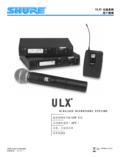
超Ul宽tra-带W频ide率Ba灵nd敏FreUquHenFcy系Ag统ile UHF Systems 自Au动to 频Fre率qu选enc择y S(eleActFioSn ()AFS) 可Re靠lia、ble专, Pr业ofe的ss音ion质al Sound Quality 多Mu系lti-统Sy操ste作m Operation
前面板 . . . . . . . . . . . . . . . . . . . . . . . . . . . . . . . . . . . . . . . . . . . . . . . . . . . . . . . . . . . . . . . . . . . . . . . . . . . . . . . . . . .
- 1、下载文档前请自行甄别文档内容的完整性,平台不提供额外的编辑、内容补充、找答案等附加服务。
- 2、"仅部分预览"的文档,不可在线预览部分如存在完整性等问题,可反馈申请退款(可完整预览的文档不适用该条件!)。
- 3、如文档侵犯您的权益,请联系客服反馈,我们会尽快为您处理(人工客服工作时间:9:00-18:30)。
射机) 同步后红色闪烁 发射机与接收机不兼容;请与 Shure 分销商联系
ᕢ 开 - 关 / 静音开关
按下并保持可开启或关闭。按下后松开可静音或取消静音。
专利号 6,597,301、 5,794,125 和 5,692,05771SH源自RE PGX 无线系统系统组件
所有系统包括 • PGX4 接收机 • 2 节 AA 电池 • 电源组件 • 用户指南
Vocalist (声乐)系统包括 • 话筒头 (可选择 PG58、 SM58 ®、 SM86 或 Beta 58A ®) • PGX2 手持式发射机 • 话筒夹
左侧数字为 组
右侧数字为 频道
在单配装中使用多个 PGX 系统时,请按照以下步骤进行操作: 1. 将所有接收机开启,同时将所有发射机关闭。 2. 确保组号在所有接收机上都相同。如有必要,应使用 “手动频率 选择”(如下图所示)将所有的接收机设置在同一个组中。 3. 在第一个接收机上执行自动频率选择 (参见第 76 页)。 4. 打开第一部发射机。 5. 执行发射机自动设置 (参见第 76 页)。
PGX Wireless User Guide
4
Shure PGX Wireless User Guide
中文版
Shure PGX 无线系统
新一代 Shure 无线系统
Shure PGX 无线系统为需要调节音效的活跃音乐家和表演者而设计,它能够 改善您的演出效果,简化您的准备工作。
自动频率选择和发射机自动设置等创新设计可以让您更迅速地使用无线系 统,而不必有任何担心。 PGX 系统现在采用 Shure 的 Audio Reference Companding (音频参考压缩扩展)专利技术,能够提供深受专业音频工程 师信赖的水晶般纯净的音响质量。
更换电池
• 一节碱性电池的预期使用时间约为 8 小时。 • 在发射机指示灯呈红色闪亮时,应按照图中
PGX1
所示立即更换电池。
调整增益
• PGX1 上有三个增益设置: • mic:话筒 • 0: 吉他 • –10: 只有在由于输入电平过高而发生声频失真时才使用
75
SHURE PGX 无线系统
单系统设置
按下并保持可开启或关闭。按下后松开可静音或取消静音。
ᕣ 红外端口
接收红外波束,使频率同步。使用多系统时,每次只应露出一个发射机红外 端口。
ᕢ
PGX
ᕣ
ᕡ
更换电池
• 一节碱性电池的预期使用时间约为 8 小时。
• 当发射机指示灯持续发红光时,应立即更换电池,如右侧 示意图所示。
调整增益
• 拧下话筒头,可以看到增益调整开关 • PGX2 上有两个增益设置 ቢ 。可以用笔尖或小螺丝刀拨
要启用新选择的组或频道,只需等待数字停止闪烁即可。
77
SHURE PGX 无线系统
故障排除
问题
没有声音或声音 微弱
指示器 (灯) 状态
发射机电源灯亮,接 收机发光二极管亮
接收机发光二级管 关闭
发射机电源指示灯 发红光或闪烁红光
发射机电源指示灯 熄灭
失真或多余的猝发 噪声
失真电平逐渐增加
其中一个数字闪烁时按 channel 按钮可以让设置数值增加 1。
要更改组 值,可在
第一个数字显示时 松开 channel 按钮 ...
... 然后按 channel 按钮 以增加该值。
要更改频道 值,可以在
显示第二位数字时 松开 channel 按钮 ...
... 然后按 channel 按钮 以增加该值。
ᕡᕢᕣ
ᕤ ᕥᕦ
ᕡ audio (音频)发光二极管 (LED)
指示拾取音频信号的强度:绿 色为正常,琥珀色为强,红色 为峰值。
ᕢ 发光二极管显示屏
请参见 “ 单系统设置 ” on page 76。
ᕣ channel (频道)按钮
请参见 “ 单系统设置 ” on page 76。
ᕤ ready (就绪)发光二极管 (LED)
audio
channel
select
< 15 cm (8 in.)
sync ready
or
sync
当接收机 ready 灯亮时,系统准备就绪可以使用。关闭发射机电池舱。
76
中文版
多系统设置
有关频道兼容信 息,请参见附带 的频率和频道指 南。
多系统设置需要使用 组 和频道。在发光二极管显示屏上,左侧的数字 表示当前组,右侧数字表示当前的频道。
PGX 提供了 8 个可供选择的系统,以及经过巡演测试的无线系统,可将其 用于吉他、器乐及声乐话筒 -其中包括富有传奇色彩的 SM58 ® 声乐话筒。 它是现场演出音响领域的佼佼者,也是您实现最佳音响效果的最简单无线系 统选择。
目录
系统组件 . . . . . . . . . . . . . . . . . . . . . . . . . . . . . . . . . . . . . . . . . . . . . . . .72 PGX4 接收机功能 . . . . . . . . . . . . . . . . . . . . . . . . . . . . . . . . . . . . . . . . .73
前面板 . . . . . . . . . . . . . . . . . . . . . . . . . . . . . . . . . . . . . . . . . . . . . . . .73 后面板 . . . . . . . . . . . . . . . . . . . . . . . . . . . . . . . . . . . . . . . . . . . . . . . .73 PGX2 手持式发射机 . . . . . . . . . . . . . . . . . . . . . . . . . . . . . . . . . . . . . . .74 更换电池 . . . . . . . . . . . . . . . . . . . . . . . . . . . . . . . . . . . . . . . . . . . . . .74 调整增益 . . . . . . . . . . . . . . . . . . . . . . . . . . . . . . . . . . . . . . . . . . . . . .74 PGX1 Bodypack 腰包发射机 . . . . . . . . . . . . . . . . . . . . . . . . . . . . . . . .75 Bodypack 腰包发射机的佩戴. . . . . . . . . . . . . . . . . . . . . . . . . . . . . . .75 更换电池 . . . . . . . . . . . . . . . . . . . . . . . . . . . . . . . . . . . . . . . . . . . . . .75 调整增益 . . . . . . . . . . . . . . . . . . . . . . . . . . . . . . . . . . . . . . . . . . . . . .75 单系统设置 . . . . . . . . . . . . . . . . . . . . . . . . . . . . . . . . . . . . . . . . . . . . . .76 多系统设置 . . . . . . . . . . . . . . . . . . . . . . . . . . . . . . . . . . . . . . . . . . . . . .77 手动频率选择. . . . . . . . . . . . . . . . . . . . . . . . . . . . . . . . . . . . . . . . . . .77 故障排除 . . . . . . . . . . . . . . . . . . . . . . . . . . . . . . . . . . . . . . . . . . . . . . . .78 锁定和解锁控制器 . . . . . . . . . . . . . . . . . . . . . . . . . . . . . . . . . . . . . . .78 规格 . . . . . . . . . . . . . . . . . . . . . . . . . . . . . . . . . . . . . . . . . . . . . . . . . . . .79 备件 . . . . . . . . . . . . . . . . . . . . . . . . . . . . . . . . . . . . . . . . . . . . . . . . . . . .80
单系统设置
1. 自动频率选择 按下并松开 channel 按钮。将扫描信号清晰的频道,然后将接收机设置在该 频道。
发光二极管屏幕显示 当前使用的频道
channel
按下 channel 按钮 搜索信号清晰的频道
系统扫描最清晰的 可用频道
2. 发射机自动设置
打开发射机
打开发射机电池舱,露出红外 (IR)端口 (请参见第 74 页和第 75 页)。 当发射机红外端口对准接收机时,按 sync (同步)按钮。 按住 Sync ( 同步 ) 按钮,直到发射机与接收机上的红色指示灯停止闪烁为 止。
动开关。
PGX
• 0dB:用于安静至正常声音的演出。
• –10dB: 只有在由于声音电平过高而发生失真
时才使用。
BIAS AUDIO
ቢ