160108_Keysight_E4991B_16196C_16092A_16192A_16197A_3GHz 阻抗分析仪操作指南(中文)
E4991A测试步骤
L、C、R器件测试步骤1.打开E4991A阻抗分析仪电源。
2.将仪器初始化:按[Preset]键3.选择扫描参数:本实验使用频率扫描(无扫描参数可跳过)a.按[Sweep]键进入扫描目录。
b.该目录下,设置扫描点数,平均点数,扫描参数和扫描类型4.设置扫描范围:100MHz-1Ga.按[start]键→ [1][0][0][M/µ]b.当前菜单下,单击向下箭头[↓],激活stop菜单c.→ [1[G/n]d.可通过屏幕下方的频率显示范围,检测频率设置是否成功。
5.设置激励信号的大小:a.按[source]键→ [↓] →点击下拉菜单选择,选择激励单位b.当前菜单下,按[↑]箭头,→ [3][0][0][k/m]输入激励信号功率。
6.测试测试台的校准:a.按[cal/compen]键进入校准界面。
b.按[ cal kit menu] ,cal kit type 下拉菜单选择校准件类型(本实验选择7mm校准件),然后返回上一层菜单。
c.按[Cal meun]键→连接开路校准件→按 [meas open] ,此时菜单变灰色,等[meas open]菜单左边出现一个√时,换上短路校准件,按[meas short] ,等[meas short]菜单左边出现一个√时,换上负载校准件。
同样的方法校准load和Low Loss C。
d.最后不要忘记按下[Done]键,完成校准。
e.此时[cal menu]从uncal变成了fix状态,表示校准已完成。
7.进行夹具补偿:(本实验使用安捷伦公司的测试夹具,只需进行open/short补偿,即可获得较高的精度)。
a.把16192A测试夹具和测试台相连,并拧紧,使夹具保持水平。
b.接上被测件,并固定住(这一步非常关键,保证补偿完成后,夹具的状态保持不变)。
c.拆下被测件,进行补偿。
d.按[comp menu]→测试终端断开,按[meas open]e.选择合适的短路连接件,进行连接(尽量不要再移动夹具的两个固定架,同时尽量使短路连接件水平放置,不要倾斜),按 [measopen]键,等补偿完毕,左边出现一个打钩标志,按[Done],完成补偿。
NI 9216 9226 8通道、400采样 秒聚合、0Ω至400Ω 4000Ω、PT100 RTD
CALIBRATION PROCEDURENI 9216/92268-Channel, 400 S/s Aggregate, 0 Ω to 400 Ω/4000 Ω,PT100RTD/PT1000 RTD C Series Temperature Input ModuleThis document contains the verification and adjustment procedures for the NI9216 and NI 9226. In this document, the NI9216 and NI9226 are inclusively referred to as NI9216/9226. For more information about calibration solutions, visit /calibration.Contents Software (1)Documentation (2)Test Equipment (3)Test Conditions (3)Initial Setup (3)Verification (4)Accuracy Verification (4)Adjustments (6)Accuracy Adjustment (6)EEPROM Update (7)Reverification (7)Accuracy Under Calibration Conditions (7)Worldwide Support and Services (8)SoftwareCalibrating the NI 9216/9226 requires the installation of NI-DAQmx 14.5 or later on the calibration system. You can download NI-DAQmx from /downloads. NI-DAQmx supports LabVIEW, LabWindows™/CVI™, ANSI C, Microsoft Visual C++, Microsoft Visual Basic .NET, and Microsoft Visual C#. When you install NI-DAQmx you only need to install support for the application software that you intend to use.2| |NI 9216/9226 Calibration ProcedureDocumentationConsult the following documents for information about the NI 9216/9226, NI-DAQmx, and your application software. All documents are available on and help files install with the software.NI cDAQ-9174/9178 Quick Start Guide NI-DAQmx installation and hardware setup NI 9216 Getting Started Guide NI 9216 connection information NI 9216 DatasheetNI 9216 circuitry and specifications NI 9226 Getting Started Guide NI 9226 connection informationNI 9226 DatasheetNI 9226 circuitry and specificationsNI-DAQmx ReadmeOperating system and application software support in NI-DAQmx LabVIEW HelpLabVIEW programming concepts and reference information about NI-DAQmx VIs and functionsNI-DAQmx C Reference HelpReference information for NI-DAQmx C functions and NI-DAQmx C properties NI-DAQmx .NET Help Support for Visual StudioReference information for NI-DAQmx .NET methods and NI-DAQmx .NETproperties, key concepts, and a C enum to .NET enum mapping tableNI 9216/9226 Calibration Procedure|© National Instruments|3Test EquipmentTable 1 lists the equipment recommended for the performance verification and adjustment procedures. If the recommended equipment is not available, select a substitute using the requirements listed in Table 1.Test ConditionsThe following setup and environmental conditions are required to ensure the NI 9216/9226 meets published specifications.•Keep connections to the device as short as possible. Long cables and wires act as antennas, picking up extra noise that can affect measurements.•Verify that all connections to the device are secure.•Use shielded copper wire for all cable connections to the device. Use twisted-pairs wire to eliminate noise and thermal offsets.•Maintain an ambient temperature of 20°C to 28°C.•Keep relative humidity below 80%.•Allow a warm-up time of at least 10minutes to ensure that the NI 9216/9226 measurement circuitry is at a stable operating temperature.Initial SetupComplete the following steps to set up the NI 9216/9226.1.Install NI-DAQmx.2.Make sure the cDAQ-9178 power source is not connected to the chassis.3.Connect the cDAQ-9178 chassis to the system safety ground.a.Attach a ring lug to a 14 AWG (1.6mm) wire.b.Connect the ring lug to the ground terminal on the side of the cDAQ-9178 chassis using the ground screw.c.Attach the other end of the wire to the system safety ground.4.Install the module in slot 8 of the cDAQ-9178 chassis. Leave slots 1 through 7 of the cDAQ-9178 chassis empty.5.Connect the cDAQ-9178 chassis to your host computer.Table 1. Recommended EquipmentEquipmentRecommendedModelsRequirementsCalibrator Fluke 5522AUse a high-precision resistance source with gain accuracy ≤40 ppm and offset error ≤2 m Ω for the NI 9216 and offset error ≤20 m Ω for the NI 9226.Chassis cDAQ-9178—6.Connect the power source to the cDAQ-9178 chassis.unch Measurement & Automation Explorer (MAX).8.Right-click the device name and select Self-Test to ensure that the module is workingproperly.VerificationThe following performance verification procedure describes the sequence of operation and test points required to verify the NI 9216/9226. The verification procedure assumes that adequate traceable uncertainties are available for the calibration references.Accuracy VerificationComplete the following procedure to determine the As-Found status of the NI9216/9226.1.Set the calibrator to Standby mode (STBY).2.Connect the desired channel of the NI 9216/9226 to the calibrator as shown in Figure 1.Connect only one channel at a time.Figure 1. 4-Wire Resistance Connections3.Set the calibrator as a resistance source to a Test Point value indicated in Table 2.4.Set calibrator COMP to 4-wire.Table 2. NI 9216/9226 Accuracy Verification Test LimitsModuleRange Test Point1-Year Limits Minimum(Ω)Maximum(Ω)Value (Ω)UpperLimit (Ω)LowerLimit (Ω)NI 9216040000.03-0.03 100100.04299.958 320320.0684319.9316NI 92260400000.3-0.3 10001000.43999.57 32003200.723199.284||NI 9216/9226 Calibration ProcedureNI 9216/9226 Calibration Procedure |© National Instruments |5Note The limits are only based on the NI 9216/9226 accuracy. The uncertainty ofcalibration standard is not included.NoteThe test limits listed in Table 2 are derived using the values in Table 6.5.Set the calibrator to Operate mode (OPR).6.Acquire and average samples from one channel.a.Create and configure a 4-wire AI resistance task on the NI 9216/9226 according to Table 3.b.Configure the ADC Timing Mode to High Resolution.NoteUse appropriate channel number in place of “x” in “AIx.” For example, useAI3 for channel 3.c.Configure the task timing according to Table 4.d.Start the task.e.Read the samples from the NI 9216/9226.f.Average the samples.g.Stop and clear the task.pare the per-channel averages to the limits in Table 2.8.Set the calibrator to Standby mode (STBY).9.Repeat steps 3 through 8 for each test point listed in Table 2.10.Disconnect the NI 9216/9226 channel from the calibrator.11.Repeat steps 2 through 10 for any other desired channel of NI 9216/9226.Table 3. NI 9216/9226 Voltage ConfigurationModulePhysical ChannelRangeMinimum (Ω)Maximum (Ω)NI 9216AIx 0400NI 9226AIx4000Table 4. NI 9216/9226 Task Timing ConfigurationSample Mode Samples Per ChannelRate (S/s)Finite Samples 1056| |NI 9216/9226 Calibration ProcedureAdjustmentsThe following performance adjustment procedure describes the sequence of operation required to adjust the NI 9216/9226.Accuracy AdjustmentComplete the following procedure to adjust the accuracy performance of the NI 9216/9226.1.Set the calibrator to Standby mode (STBY).2.Connect the desired channel of the NI 9216/9226 to the calibrator as shown in Figure 1. Connect only one channel at a time.3.Adjust the desired channel of the NI 9216/9226.a.Initialize a calibration session on the NI 9216/9226. The default password is NI .b.Input the external temperature in degrees Celsius.c.Call the DAQmx Get NI 9216/9226 Calibration Adjustment Points function to obtain an array of recommended calibration resistance values.d.Set the calibrator to a reference value determined by the array of recommended calibration voltages.e.Set calibrator COMP to 4-wire.f.Set the calibrator to Operate mode (OPR).g.Call and configure the NI 9216/9226 adjustment function according to Table 5.Note Use appropriate channel number in place of “x” in “AIx.” For example, useAI3 for channel 3.NoteThe module acquisition is started each time the adjust function is called.h.Set the calibrator to Standby mode (STBY).i.Repeat steps d through h for each point in the array.j.Close the calibration session with action commit.4.Disconnect the NI 9216/9226 channel from the calibrator.5.Repeat steps 2 through 4 to calibrate any other desired channel of NI 9216/9226.Table 5. Gain Adjustment ConfigurationPhysical Channel Reference ValueAIxThe reference resistance value from the arrayof adjustment pointsNI 9216/9226 Calibration Procedure |© National Instruments |7EEPROM UpdateWhen an adjustment procedure is completed, the NI 9216/9226 internal calibration memory (EEPROM) is immediately updated.If you do not want to perform an adjustment, you can update the calibration date and onboard calibration temperature without making any adjustments by initializing an external calibration , setting the C Series calibration temperature, and closing the external calibration.ReverificationRepeat the Verification section to determine the As-Left status of the device.NoteIf any test fails Reverification after performing an adjustment, verify that youhave met the Test Conditions before returning your device to NI. Refer to Worldwide Support and Services for assistance in returning the device to NI.Accuracy Under Calibration ConditionsThe values in the following table are based on calibrated scaling coefficients, which are stored in the onboard EEPROM.The following accuracy table is valid for calibration under the following conditions:•Ambient temperature 20°C to 28°C•NI 9216/9226 installed in slot 8 of an cDAQ-9178 chassis •Slots 1 through 7 of the cDAQ-9178 chassis are emptyNoteFor operational specifications, refer to the most recent NI 9216 Datasheet orNI 9226 Datasheet online at /manuals .Table 6. NI 9216/9226 Accuracy Under Calibration ConditionsModule Gain Error Offset ErrorNI 9216±0.012%±0.03 ΩNI 9226±0.013%±0.3Ω©2015–2018 National Instruments. All rights reserved. 375425C-01Oct18Refer to the NI Trademarks and Logo Guidelines at /trademarks for more information on National Instruments trademarks. Other product and company names mentioned herein are trademarks or trade names of their respective companies. For patents covering NationalInstruments products/technology, refer to the appropriate location: Help»Patents in your software, the patents.txt file on your media, or the National Instruments Patents Notice at /patents . You can find information about end-user license agreements (EULAs) and third-party legal notices in the readme file for your NI product. Refer to the Export Compliance Information at /legal/export-compliance for the National Instruments global trade compliance policy and how to obtain relevant HTS codes, ECCNs, and other import/export data. NI MAKES NO EXPRESS OR IMPLIED WARRANTIES AS TO THE ACCURACY OF THE INFORMATION CONTAINED HEREIN AND SHALL NOT BE LIABLE FOR ANY ERRORS. U.S. Government Customers: The data contained in this manual was developed at private expense and is subject to the applicable limited rights and restricted data rights as set forth in FAR 52.227-14, DFAR 252.227-7014, and DFAR 252.227-7015.Worldwide Support and ServicesThe NI website is your complete resource for technical support. At /support you have access to everything from troubleshooting and application development self-help resources to email and phone assistance from NI Application Engineers.Visit /services for NI Factory Installation Services, repairs, extended warranty, and other services.Visit /register to register your NI product. Product registration facilitates technical support and ensures that you receive important information updates from NI.NI corporate headquarters is located at 11500 North Mopac Expressway, Austin, Texas,78759-3504. NI also has offices located around the world. For telephone support in the United States, create your service request at /support or dial 1866ASK MYNI (2756964). For telephone support outside the United States, visit the Worldwide Offices section of/niglobal to access the branch office websites, which provide up-to-date contact information, support phone numbers, email addresses, and current events.。
Keysight波导功率传感器说明书

E8486A, V8486A and W8486A Waveguide Power SensorsMake accurate and reliable measurements in the 50 to 110 GHz frequency range with Keysight’s family of waveguide power sensorsCovering the V-band, E-band and W-band spectrums, the Keysight Technologies, Inc. waveguide power sensors offer best SWR, high reliability and low loss, and come with a 50 MHz calibration port to reduce measurement uncertainties. And with the Keysight E8486A (Option 200) waveguide sensor, you also get a wide dynamic range spanning from -60 to +20 dBm.Compatible with your current Keysight power meterKeysight waveguide power sensors are fully compatible with Keysight EPM (E4418B/19B, N1913A/14A), EPM-P (E4416A/17A) and P-Series (N1911A/12A) power meters. The V8486A and W8486A are also compatible with the discontinued or obsolete power meters such as 435B, 436A, 437B, 438A, 70100A,E1416A, E4418A, and E4419A power meters.Best SWR availableIn RF and microwave power measurements, the largest single source of error is usually sensor and source mismatch. To minimize any measurement uncertainty caused by mismatch, Keysightwaveguide sensors offer excellent SWR of 1.06 (> 30 dB return loss).50 MHz calibrationFor easy calibration with the power meter, Keysight waveguide power sensors incorporate a50 MHz calibration port. This eliminates the variance in making measurements with different meter/sensor combinations and the uncertainties due to temperature changes. It also provides traceability to the U.S National Institute of Standards and Technology (NIST) at millimeter-wave frequencies.High reliabilityKeysight waveguide sensors use the same proven Modified Barrier Integrated Diode (MBID)technology found in other Keysight sensors, and always operates in the square-law characteristic fortrue-average detection.Waveguide power sensors comparison tableModel FrequencyrangePower linearity 1Maximum power Connector typeE8486A-100 60 to 90 GHz -30 to +10 dBm: < ±1%200 mW avg, 40 W pk(10 μs per pulse, 0.5% duty cycle)Waveguide flange:UG-387/U Flange, EIA WR-12 +10 to +20 dBm: < ±2% 2+10 to +20 dBm: < +1, -3% 3E8486A-200 60 to 90 GHz -60 to -30 dBm: < ±1.5%200 mW avg, 1 W pk(10 μs per pulse, 0.5% duty cycle)Waveguide flange:UG-387/U Flange, EIA WR-12 -30 to +10 dBm: < 1.5%+10 to +20 dBm: < ±1.5%V8486A 50 to 75 GHz -30 to +10 dBm: < ±1% 200 mW avg, 40 W pk(10 μs per pulse, 0.5% duty cycle)Waveguide flange:UG-385/U+10 to +20 dBm: < ±2%W8486A 75 to 110 GHz -30 to +20 dBm: < ±2% 200 mW avg, 40 W pk(10 μs per pulse, 0.5% duty cycle)Waveguide flange:UG-387/U1. Negligible deviation except for those power ranges noted.2. For EPM series power meters.3. For all other Keysight power meters.Supplemental characteristics, which are shown in italics, are intended to provide additional information, useful in applying the power sensors by giving typical, but not warranted performance parameters. These characteristics are shown in italics or denoted as “typical”, “nominal” or “approximate”.E8486A E-Band Waveguide Power SensorMeet the rapid demand in E-band telecommunication applications with the E8486A waveguide power sensor. Designed with a WR-12 flange connector, the E8486A makes precise and direct waveguide measurements in the E-band frequency range and is compatible with most Keysight power meters. A wide dynamic range of -60 to +20 dBm and a SWR performance of 1.06 minimize measurement uncertainty caused by mismatch, providing high accuracy even with low power signals. With the E8486A waveguide power sensor, get the precision and accuracy you need for E-band applications in a single power sensor.Figure 1. E8486A-100 comes without built-in EEPROM with dynamic range of -30 to +20 dBm. Users need to pre-enter calibration factors printed on the back of the sensor into the power meter.Figure 2. E8486A-200 comes with built-in EEPROM to store calibration factors with extended dynamic range of -60 to +20 dBm.SpecificationsSpecification DescriptionPower rangeOption 100: 1 μW to 100 mW (-30 to +20 dBm)Option 200: 1 nW to 100 mW (-60 to +20 dBm)Frequency range 160 to 90 GHzCalibration factor inputOption 100: Does not include EEPROM. Users need to pre-enter calibration factors into thepower meter; the calibration factor label will be provided on the power sensor unit.Option 200: Comes with EEPROM to store calibration factors. Users simply need to input thefrequency and the correct calibration factor will be applied.Maximum SWROption 100: < 1.06Option 200: < 1.28Maximum SWR at 50 MHzOption 100: < 1.066Option 200: < 1.077Maximum Calibration Factor RelativeUncertainty 260 GHz to 64 GHz: 6.4%> 64 GHz to 68 GHz: 5.7%> 68 GHz to 74 GHz: 6.1%> 74 GHz to 79 GHz: 7.3%> 79 GHz to 90 GHz: 6.9%Maximum power (damage level)Option 100: 200 mW avg, 40 W pk (10 μs per pulse, 0.5% duty cycle)Option 200: 200 mW avg, 1 W pk (10 μs per pulse, 0.5% duty cycle)1. Option 201 is a standard E8486A-200 that has been calibrated at an extended frequency (54 to 95 GHz). Refer to E8486AOption 201 Product Note (E8486-90701) for more details.2. The characterized calibration factor should not deviate between periodic calibrations by more than the specified maximumuncertainty in the table. Compliance is confirmed by the relative deviation(|CF1–CF2|CF1x100)being less than or equal to √2 timesthe specified maximum uncertainty. √2∗Umax with a reference calibration factor of 100%.Make accurate average power measurements from 50 to 75 GHz with the V8486A V-band power sensor.A special option for the V8486A that extends the power range down to -60 dBm is available. Contact your local Keysight field engineer or sales office for more information.Figure 3. V8486A comes without built-in EEPROM. Users need to pre-enter calibration factors printed on the back of the sensor into the power meter.Specifications3. The characterized calibration factor should not deviate between periodic calibrations by more than the specifiedmaximum uncertainty in the table. Compliance is confirmed by the relative deviation(|CF1–CF2|CF1x100) being less thanor equal to √2 times the specified maximum uncertainty. √2∗Umax with a reference calibration factor of 100%.The W8486A waveguide power sensor measures average power over the frequency range 75 to110 GHz and power range –30 to +20 dBm.Figure 4. W8486A comes without built-in EEPROM. Users need to pre-enter calibration factors printed on the back of the sensor into the power meter.SpecificationsSpecification DescriptionPower range -30 to +20 dBmFrequency range 75 to 110 GHzMaximum SWR < 1.08Maximum SWR at 50 MHz < 1.076Maximum Calibration Factor Relative Uncertainty 475 GHz to 79 GHz: 7.86%> 79 GHz to 94 GHz: 7.24% > 94 GHz to 103 GHz: 6.98% > 103 GHz to 108 GHz: 7.24% > 108 GHz to 110 GHz: 7.77%Maximum power (waveguide port only) 200 mW average, 40 W peak (10 μs pul se, 0.5% duty cycle) or equivalent such that 200 mW maximum average power and 40 W peak power are not exceededPower linearity -30 to +20 dBm: < ±2% Zero set < ±200 nW Measurement noise < 450 nWZero drift < ±40 pWWeight Net: 0.4 kg (0.9 lb) Shipping: 1.0 kg (2.2 lb)Connector type Waveguide flange: UG-387/UCalibration Cycle 1 year4. The characterized calibration factor should not deviate between periodic calibrations by more than the specified maximumuncertainty in the table. Compliance is confirmed by the relative deviation(|CF1–CF2|CF1x100)being less than or equal to √2 timesthe specified maximum uncertainty. √2∗Umax with a reference calibration factor of 100%.Learn more at: For more information on Keysight Technologies’ products, applications or services, please contact your local Keysight office. The complete list is available at: /find/contactusMechanical characteristicMechanical characteristics such as center conductor protrusion and pin depth are not performance specifications. They are, however, important supplemental characteristics related to electrical performance. At no time should the pin depth of the connector be protruding.Calibration factor and reflection coefficientCalibration factor (CF) and reflection coefficient (Rho) data is unique to each sensor. The CF corrects for the frequency response of the sensor. The reflection coefficient (Rho or ρ) relates to the SWR based onthe following formula: SWR = 1+ρ1−ρ. Maximum relative uncertainties of the CF data are listed in eachwaveguide’s respective tables. The relative uncertainty analysis for the calibration data was done in accordance with ISO Guide. The uncertainty data reported on the calibration certificate is the expanded uncertainty with a 95% confidence level and a coverage factor of 2.Ordering InformationModelDescriptionE-Band E8486A-100 E8486A-200 E8486A-201 E-band power sensor, 60 to 90 GHz, -30 to +20 dBm E-band power sensor, 60 to 90 GHz, -60 to +20 dBm E-band power sensor, 54 to 95 GHz, -60 to +20 dBm V-Band V8486A V-band power sensor, 50 to 75 GHz, -30 to +20 dBm W-BandW8486AW-band power sensor, 75 to 110 GHz, -30 to +20 dBmStandard shipped accessories Hex ball driverWaveguide mounting screws User’s and Service Guide, English。
Keysight E4980A AL Precision LCR Meter 用户指南说明书
Keysight E4980A/AL Precision LCR MeterUser’s GuideNotices© Keysight Technologies2006-2019No part of this manual may be reproduced in any form or by any means (including electronic storage and retrieval or translation into a foreign language) without prior agreement and written consent from Keysight Technologies, Inc. as governed by United States and international copyright laws. Trademark Acknowledgments Manual Part NumberE4980-90230EditionEdition 16, October 2019 Printed in MalaysiaPublished by:Keysight Technologies International Japan G.K,1-3-3 Higashikawasaki-choChuo-kuKobe-shi, Hyogo, Japan WarrantyTHE MATERIAL CONTAINED IN THIS DOCUMENT IS PROVIDED “AS IS,” AND IS SUBJECT TO BEING CHANGED, WITHOUT NOTICE, IN FUTURE EDITIONS. FURTHER, TO THE MAXIMUM EXTENT PERMITTED BY APPLICABLE LAW, KEYSIGHT DISCLAIMS ALL WARRANTIES, EITHER EXPRESS OR IMPLIED WITH REGARD TO THIS MANUAL AND ANY INFORMATION CONTAINED HEREIN, INCLUDING BUT NOT LIMITED TO THE IMPLIED WARRANTIES OF MERCHANTABILITY AND FITNESS FOR A PARTICULAR PURPOSE. KEYSIGHT SHALL NOT BE LIABLE FOR ERRORS OR FOR INCIDENTAL OR CONSEQUENTIAL DAMAGES IN CONNECTION WITH THE FURNISHING, USE, OR PERFORMANCE OF THIS DOCUMENT OR ANY INFORMATION CONTAINED HEREIN. SHOULD KEYSIGHT AND THE USER HAVE A SEPARATE WRITTEN AGREEMENT WITH WARRANTY TERMS COVERING THE MATERIAL IN THISDOCUMENT THAT CONFLICT WITHTHESE TERMS, THE WARRANTYTERMS IN THE SEPARATEAGREEMENT WILL CONTROL.Technology LicensesThe hardware and/or softwaredescribed in this document arefurnished under a license and may beused or copied only in accordancewith the terms of such license.Declaration of ConformityDeclarations of Conformity for thisproduct and for other Keysightproducts may be downloaded fromthe Web. Go to/go/conformity. You can then search by productnumber to find the latest Declarationof Conformity.U.S. Government RightsThe Software is “commercialcomputer software,” as defined byFederal Acquisition Regulation(“FAR”) 2.101. Pursuant to FAR12.212 and 27.405-3 andDepartment of Defense FARSupplement (“DFARS”) 227.7202, theU.S. government acquirescommercial computer softwareunder the same terms by which thesoftware is customarily provided tothe public. Accordingly, Keysightprovides the Software to U.S.government customers under itsstandard commercial license, whichis embodied in its End User LicenseAgreement (EULA), a copy of whichcan be found at/find/sweula. The license set forth in the EULArepresents the exclusive authority bywhich the U.S. government may use,modify, distribute, or disclose theSoftware. The EULA and the licenseset forth therein, does not require orpermit, among other things, thatKeysight: (1) Furnish technicalinformation related to commercialcomputer software or commercialcomputer software documentationthat is not customarily provided tothe public; or (2) Relinquish to, orotherwise provide, the governmentrights in excess of these rightscustomarily provided to the public touse, modify, reproduce, release,perform, display, or disclosecommercial computer software orcommercial computer softwaredocumentation. No additionalgovernment requirements beyondthose set forth in the EULA shallapply, except to the extent that thoseterms, rights, or licenses areexplicitly required from all providersof commercial computer softwarepursuant to the FAR and the DFARSand are set forth specifically inwriting elsewhere in the EULA.Keysight shall be under no obligationto update, revise or otherwise modifythe Software. With respect to anytechnical data as defined by FAR2.101, pursuant to FAR 12.211 and27.404.2 and DFARS 227.7102, theU.S. government acquires no greaterthan Limited Rights as defined in FAR27.401 or DFAR 227.7103-5 (c), asapplicable in any technical data.Safety NoticesA CAUTION notice denotes a hazard. Itcalls attention to an operatingprocedure, practice, or the like that,if not correctly performed or adheredto, could result in damage to theproduct or loss of important data. Donot proceed beyond a CAUTIONnotice until the indicated conditionsare fully understood and met.A WARNING notice denotes a hazard.It calls attention to an operatingprocedure, practice, or the like that,if not correctly performed or adheredto, could result in personal injury ordeath. Do not proceed beyond aWARNING notice until the indicatedconditions are fully understood andmet.ContentsKeysight E4980A/AL User’s Guide 3Table of Contents1.Unpacking and PreparationContents of this Chapter . . . . . . . . . . . . . . . . . . . . . . . . . . . . . . . . . . . . . . . . . . . . . . . . . . . . . 17Checking the Shipment . . . . . . . . . . . . . . . . . . . . . . . . . . . . . . . . . . . . . . . . . . . . . . . . . . . . . . 18Preparations before Use. . . . . . . . . . . . . . . . . . . . . . . . . . . . . . . . . . . . . . . . . . . . . . . . . . . . . . 20Verifying the Power Supply . . . . . . . . . . . . . . . . . . . . . . . . . . . . . . . . . . . . . . . . . . . . . . . . 20Setting up the Fuse . . . . . . . . . . . . . . . . . . . . . . . . . . . . . . . . . . . . . . . . . . . . . . . . . . . . . . 20Verifying and Connecting the Power Cable. . . . . . . . . . . . . . . . . . . . . . . . . . . . . . . . . . . . 21How to Remove the Handle. . . . . . . . . . . . . . . . . . . . . . . . . . . . . . . . . . . . . . . . . . . . . . . . . . . 23Caution when Using the Handle . . . . . . . . . . . . . . . . . . . . . . . . . . . . . . . . . . . . . . . . . . . . . . . 24Environmental Requirements. . . . . . . . . . . . . . . . . . . . . . . . . . . . . . . . . . . . . . . . . . . . . . . . . . 25Operating Environments. . . . . . . . . . . . . . . . . . . . . . . . . . . . . . . . . . . . . . . . . . . . . . . . . . . 25Ventilation Requirements. . . . . . . . . . . . . . . . . . . . . . . . . . . . . . . . . . . . . . . . . . . . . . . . . . 26Protection Against Electrostatic Discharge (ESD). . . . . . . . . . . . . . . . . . . . . . . . . . . . . . . 27Ensuring Adequate Free Space around the LCR meter for Immediate Disconnection of the Power Cable in Case of Emergency. . . . . . . . . . . . . . . . . . . . . . . . . . . . . . . . . . . . . . . . . . 27Starting the E4980A/AL. . . . . . . . . . . . . . . . . . . . . . . . . . . . . . . . . . . . . . . . . . . . . . . . . . . . . . 28Turning the Power ON and OFF. . . . . . . . . . . . . . . . . . . . . . . . . . . . . . . . . . . . . . . . . . . . . 28Disconnecting from the Supply Source. . . . . . . . . . . . . . . . . . . . . . . . . . . . . . . . . . . . . . . 292.OverviewProduct Introduction. . . . . . . . . . . . . . . . . . . . . . . . . . . . . . . . . . . . . . . . . . . . . . . . . . . . . . . . . 31Front Panel: Names and Functions of Parts . . . . . . . . . . . . . . . . . . . . . . . . . . . . . . . . . . . . . . 321. Power switch . . . . . . . . . . . . . . . . . . . . . . . . . . . . . . . . . . . . . . . . . . . . . . . . . . . . . . . . . 332. LCD . . . . . . . . . . . . . . . . . . . . . . . . . . . . . . . . . . . . . . . . . . . . . . . . . . . . . . . . . . . . . . . . 333. Softkeys . . . . . . . . . . . . . . . . . . . . . . . . . . . . . . . . . . . . . . . . . . . . . . . . . . . . . . . . . . . . . 334. Menu keys. . . . . . . . . . . . . . . . . . . . . . . . . . . . . . . . . . . . . . . . . . . . . . . . . . . . . . . . . . . . 335. Cursor keys. . . . . . . . . . . . . . . . . . . . . . . . . . . . . . . . . . . . . . . . . . . . . . . . . . . . . . . . . . . 336. Entry keys. . . . . . . . . . . . . . . . . . . . . . . . . . . . . . . . . . . . . . . . . . . . . . . . . . . . . . . . . . . . 347. LED indicator . . . . . . . . . . . . . . . . . . . . . . . . . . . . . . . . . . . . . . . . . . . . . . . . . . . . . . . . . 348. Preset key. . . . . . . . . . . . . . . . . . . . . . . . . . . . . . . . . . . . . . . . . . . . . . . . . . . . . . . . . . . . 349. Trigger key . . . . . . . . . . . . . . . . . . . . . . . . . . . . . . . . . . . . . . . . . . . . . . . . . . . . . . . . . . . 3410. DC Bias key. . . . . . . . . . . . . . . . . . . . . . . . . . . . . . . . . . . . . . . . . . . . . . . . . . . . . . . . . . 3411. DC Source key . . . . . . . . . . . . . . . . . . . . . . . . . . . . . . . . . . . . . . . . . . . . . . . . . . . . . . . 3412. UNKNOWN terminals . . . . . . . . . . . . . . . . . . . . . . . . . . . . . . . . . . . . . . . . . . . . . . . . . 3513. Front USB port . . . . . . . . . . . . . . . . . . . . . . . . . . . . . . . . . . . . . . . . . . . . . . . . . . . . . . . 3514. Ground terminal. . . . . . . . . . . . . . . . . . . . . . . . . . . . . . . . . . . . . . . . . . . . . . . . . . . . . . 3615. DC Source terminal . . . . . . . . . . . . . . . . . . . . . . . . . . . . . . . . . . . . . . . . . . . . . . . . . . . 36Rear Panel: Names and Functions of Parts . . . . . . . . . . . . . . . . . . . . . . . . . . . . . . . . . . . . . . . 371. GPIB Interface Connector . . . . . . . . . . . . . . . . . . . . . . . . . . . . . . . . . . . . . . . . . . . . . . . 37Contents2. Interface Connector. . . . . . . . . . . . . . . . . . . . . . . . . . . . . . . . . . . . . . . . . . . . . . . . . . . . .373. USB (USBTMC) Interface Port. . . . . . . . . . . . . . . . . . . . . . . . . . . . . . . . . . . . . . . . . . . . .384. LAN Port . . . . . . . . . . . . . . . . . . . . . . . . . . . . . . . . . . . . . . . . . . . . . . . . . . . . . . . . . . . . .385. External Trigger Input Connector . . . . . . . . . . . . . . . . . . . . . . . . . . . . . . . . . . . . . . . . . .386. Serial Number Plate . . . . . . . . . . . . . . . . . . . . . . . . . . . . . . . . . . . . . . . . . . . . . . . . . . . .387. Power Cable Receptacle (to LINE) . . . . . . . . . . . . . . . . . . . . . . . . . . . . . . . . . . . . . . . . .398. Fan. . . . . . . . . . . . . . . . . . . . . . . . . . . . . . . . . . . . . . . . . . . . . . . . . . . . . . . . . . . . . . . . . .39Screen Area: Names and Functions of Parts. . . . . . . . . . . . . . . . . . . . . . . . . . . . . . . . . . . . . . .401. Display Page Area . . . . . . . . . . . . . . . . . . . . . . . . . . . . . . . . . . . . . . . . . . . . . . . . . . . . . .402. Comment Line Area. . . . . . . . . . . . . . . . . . . . . . . . . . . . . . . . . . . . . . . . . . . . . . . . . . . . .403. Softkey Area. . . . . . . . . . . . . . . . . . . . . . . . . . . . . . . . . . . . . . . . . . . . . . . . . . . . . . . . . . .414. Measurement Data/Conditions Area. . . . . . . . . . . . . . . . . . . . . . . . . . . . . . . . . . . . . . . .415. Input Line Area . . . . . . . . . . . . . . . . . . . . . . . . . . . . . . . . . . . . . . . . . . . . . . . . . . . . . . . .426. System Message Area. . . . . . . . . . . . . . . . . . . . . . . . . . . . . . . . . . . . . . . . . . . . . . . . . . .427. Status Display Area. . . . . . . . . . . . . . . . . . . . . . . . . . . . . . . . . . . . . . . . . . . . . . . . . . . . .42Basic Operation. . . . . . . . . . . . . . . . . . . . . . . . . . . . . . . . . . . . . . . . . . . . . . . . . . . . . . . . . . . . .43 How to Use Cursor Keys . . . . . . . . . . . . . . . . . . . . . . . . . . . . . . . . . . . . . . . . . . . . . . . . . . .43 How to Use Skip Keys. . . . . . . . . . . . . . . . . . . . . . . . . . . . . . . . . . . . . . . . . . . . . . . . . . . . .44 3.Display FormatMEAS DISPLAY Page. . . . . . . . . . . . . . . . . . . . . . . . . . . . . . . . . . . . . . . . . . . . . . . . . . . . . . . . .45 Measurement Function . . . . . . . . . . . . . . . . . . . . . . . . . . . . . . . . . . . . . . . . . . . . . . . . . . . .47 Impedance range. . . . . . . . . . . . . . . . . . . . . . . . . . . . . . . . . . . . . . . . . . . . . . . . . . . . . . . . .51 Test Frequency. . . . . . . . . . . . . . . . . . . . . . . . . . . . . . . . . . . . . . . . . . . . . . . . . . . . . . . . . . .58 Test Signal Level . . . . . . . . . . . . . . . . . . . . . . . . . . . . . . . . . . . . . . . . . . . . . . . . . . . . . . . . .61 DC Bias . . . . . . . . . . . . . . . . . . . . . . . . . . . . . . . . . . . . . . . . . . . . . . . . . . . . . . . . . . . . . . . .64 Measurement Time Mode . . . . . . . . . . . . . . . . . . . . . . . . . . . . . . . . . . . . . . . . . . . . . . . . . .68 Display Setting for Measurement Results. . . . . . . . . . . . . . . . . . . . . . . . . . . . . . . . . . . . . .69 Displaying Errors instead of Measurement Results . . . . . . . . . . . . . . . . . . . . . . . . . . . . . .71 Monitor Information. . . . . . . . . . . . . . . . . . . . . . . . . . . . . . . . . . . . . . . . . . . . . . . . . . . . . . .75 BIN NO. DISPLAY Page . . . . . . . . . . . . . . . . . . . . . . . . . . . . . . . . . . . . . . . . . . . . . . . . . . . . . . .76 Comparator Function ON/OFF . . . . . . . . . . . . . . . . . . . . . . . . . . . . . . . . . . . . . . . . . . . . . .77 BIN COUNT DISPLAY Page . . . . . . . . . . . . . . . . . . . . . . . . . . . . . . . . . . . . . . . . . . . . . . . . . . . .79 Counter Function. . . . . . . . . . . . . . . . . . . . . . . . . . . . . . . . . . . . . . . . . . . . . . . . . . . . . . . . .81 LIST SWEEP DISPLAY Page. . . . . . . . . . . . . . . . . . . . . . . . . . . . . . . . . . . . . . . . . . . . . . . . . . . .82 Sweep Mode . . . . . . . . . . . . . . . . . . . . . . . . . . . . . . . . . . . . . . . . . . . . . . . . . . . . . . . . . . . .84 DISPLAY BLANK Page. . . . . . . . . . . . . . . . . . . . . . . . . . . . . . . . . . . . . . . . . . . . . . . . . . . . . . . .86 4.Configuring Measurement Conditions (Display and Function Related Settings)Initializing the Instrument . . . . . . . . . . . . . . . . . . . . . . . . . . . . . . . . . . . . . . . . . . . . . . . . . . . . .87 MEAS SETUP page . . . . . . . . . . . . . . . . . . . . . . . . . . . . . . . . . . . . . . . . . . . . . . . . . . . . . . . . . .884 Keysight E4980A/AL User’s GuideContentsKeysight E4980A/AL User’s Guide 5Comment line. . . . . . . . . . . . . . . . . . . . . . . . . . . . . . . . . . . . . . . . . . . . . . . . . . . . . . . . . . . 90Trigger mode . . . . . . . . . . . . . . . . . . . . . . . . . . . . . . . . . . . . . . . . . . . . . . . . . . . . . . . . . . . 91Automatic level control . . . . . . . . . . . . . . . . . . . . . . . . . . . . . . . . . . . . . . . . . . . . . . . . . . . 93DC Bias Current Isolation. . . . . . . . . . . . . . . . . . . . . . . . . . . . . . . . . . . . . . . . . . . . . . . . . . 97Averaging Factor . . . . . . . . . . . . . . . . . . . . . . . . . . . . . . . . . . . . . . . . . . . . . . . . . . . . . . . . 98Trigger Delay Time . . . . . . . . . . . . . . . . . . . . . . . . . . . . . . . . . . . . . . . . . . . . . . . . . . . . . . . 99Step Delay Time. . . . . . . . . . . . . . . . . . . . . . . . . . . . . . . . . . . . . . . . . . . . . . . . . . . . . . . . 101DC Bias Voltage Monitor . . . . . . . . . . . . . . . . . . . . . . . . . . . . . . . . . . . . . . . . . . . . . . . . . 103DC Bias Current Monitor . . . . . . . . . . . . . . . . . . . . . . . . . . . . . . . . . . . . . . . . . . . . . . . . . 104DCR Range. . . . . . . . . . . . . . . . . . . . . . . . . . . . . . . . . . . . . . . . . . . . . . . . . . . . . . . . . . . . 105DCI Range. . . . . . . . . . . . . . . . . . . . . . . . . . . . . . . . . . . . . . . . . . . . . . . . . . . . . . . . . . . . . 106DC Source. . . . . . . . . . . . . . . . . . . . . . . . . . . . . . . . . . . . . . . . . . . . . . . . . . . . . . . . . . . . . 107Automatic Bias Polarity Control . . . . . . . . . . . . . . . . . . . . . . . . . . . . . . . . . . . . . . . . . . . 108Deviation Measurement. . . . . . . . . . . . . . . . . . . . . . . . . . . . . . . . . . . . . . . . . . . . . . . . . . 110CORRECTION page . . . . . . . . . . . . . . . . . . . . . . . . . . . . . . . . . . . . . . . . . . . . . . . . . . . . . . . . 112To set the correction function to on or off. . . . . . . . . . . . . . . . . . . . . . . . . . . . . . . . . . . . 113The correction functions of the E4980A/AL are operated as follows:. . . . . . . . . . . . . . . 114Open Correction. . . . . . . . . . . . . . . . . . . . . . . . . . . . . . . . . . . . . . . . . . . . . . . . . . . . . . . . 115Short Correction. . . . . . . . . . . . . . . . . . . . . . . . . . . . . . . . . . . . . . . . . . . . . . . . . . . . . . . . 119Correction Based on User-Specified Frequency Points. . . . . . . . . . . . . . . . . . . . . . . . . . 121Relationships between Correction Based on All Frequency Points and Correction Based on Specified Frequency Points . . . . . . . . . . . . . . . . . . . . . . . . . . . . . . . . . . . . . . . . . . . . . . . 128Reading/Writing Correction Data . . . . . . . . . . . . . . . . . . . . . . . . . . . . . . . . . . . . . . . . . . 130Measurement Functions for the Standard. . . . . . . . . . . . . . . . . . . . . . . . . . . . . . . . . . . . 131Selecting Single/Multiple Correction Mode . . . . . . . . . . . . . . . . . . . . . . . . . . . . . . . . . . 132Selecting the Cable Length . . . . . . . . . . . . . . . . . . . . . . . . . . . . . . . . . . . . . . . . . . . . . . . 133LIMIT TABLE SETUP Page . . . . . . . . . . . . . . . . . . . . . . . . . . . . . . . . . . . . . . . . . . . . . . . . . . . 134Parameter Swap Feature . . . . . . . . . . . . . . . . . . . . . . . . . . . . . . . . . . . . . . . . . . . . . . . . . 135Comparator Limit Mode. . . . . . . . . . . . . . . . . . . . . . . . . . . . . . . . . . . . . . . . . . . . . . . . . . 137Tolerance Mode Nominal Value. . . . . . . . . . . . . . . . . . . . . . . . . . . . . . . . . . . . . . . . . . . . 139Turning On/Off the Comparator. . . . . . . . . . . . . . . . . . . . . . . . . . . . . . . . . . . . . . . . . . . . 140Turning On/Off the Auxiliary Bin . . . . . . . . . . . . . . . . . . . . . . . . . . . . . . . . . . . . . . . . . . . 141Beep Feature . . . . . . . . . . . . . . . . . . . . . . . . . . . . . . . . . . . . . . . . . . . . . . . . . . . . . . . . . . 143Lower and Upper Limits . . . . . . . . . . . . . . . . . . . . . . . . . . . . . . . . . . . . . . . . . . . . . . . . . 144LIST SWEEP SETUP Page . . . . . . . . . . . . . . . . . . . . . . . . . . . . . . . . . . . . . . . . . . . . . . . . . . . 147Sweep Mode. . . . . . . . . . . . . . . . . . . . . . . . . . . . . . . . . . . . . . . . . . . . . . . . . . . . . . . . . . . 148List Sweep Parameters. . . . . . . . . . . . . . . . . . . . . . . . . . . . . . . . . . . . . . . . . . . . . . . . . . . 149Sweep Points and Limit Modes . . . . . . . . . . . . . . . . . . . . . . . . . . . . . . . . . . . . . . . . . . . . 150Sweep Parameter Auto-completion . . . . . . . . . . . . . . . . . . . . . . . . . . . . . . . . . . . . . . . . 1535.System ConfigurationsSYSTEM INFO Page . . . . . . . . . . . . . . . . . . . . . . . . . . . . . . . . . . . . . . . . . . . . . . . . . . . . . . . . 155ContentsHandler Interface. . . . . . . . . . . . . . . . . . . . . . . . . . . . . . . . . . . . . . . . . . . . . . . . . . . . . . . .156 Scanner Interface . . . . . . . . . . . . . . . . . . . . . . . . . . . . . . . . . . . . . . . . . . . . . . . . . . . . . . .157 Monitor Information. . . . . . . . . . . . . . . . . . . . . . . . . . . . . . . . . . . . . . . . . . . . . . . . . . . . . .157 SYSTEM CONFIG Page . . . . . . . . . . . . . . . . . . . . . . . . . . . . . . . . . . . . . . . . . . . . . . . . . . . . . .158 Turning On/Off the Beep Feature . . . . . . . . . . . . . . . . . . . . . . . . . . . . . . . . . . . . . . . . . . .159 Changing the Beep Tone . . . . . . . . . . . . . . . . . . . . . . . . . . . . . . . . . . . . . . . . . . . . . . . . .160 Changing the Beep Tone . . . . . . . . . . . . . . . . . . . . . . . . . . . . . . . . . . . . . . . . . . . . . . . . .161 Configuring the System Date . . . . . . . . . . . . . . . . . . . . . . . . . . . . . . . . . . . . . . . . . . . . . .161 Configuring the GPIB Address. . . . . . . . . . . . . . . . . . . . . . . . . . . . . . . . . . . . . . . . . . . . . .163 Configuring the LAN IP address . . . . . . . . . . . . . . . . . . . . . . . . . . . . . . . . . . . . . . . . . . . .164 SELF TEST Page . . . . . . . . . . . . . . . . . . . . . . . . . . . . . . . . . . . . . . . . . . . . . . . . . . . . . . . . . . .166 Choosing a Test Item. . . . . . . . . . . . . . . . . . . . . . . . . . . . . . . . . . . . . . . . . . . . . . . . . . . . .167 SERVICE Page. . . . . . . . . . . . . . . . . . . . . . . . . . . . . . . . . . . . . . . . . . . . . . . . . . . . . . . . . . . . .168 Monitor Information. . . . . . . . . . . . . . . . . . . . . . . . . . . . . . . . . . . . . . . . . . . . . . . . . . . . . .169 Saving the System Information into External Memory. . . . . . . . . . . . . . . . . . . . . . . . . . .169 6.Save/RecallOverview of Save/Recall Functionality . . . . . . . . . . . . . . . . . . . . . . . . . . . . . . . . . . . . . . . . . .171 Save Methods and Their Uses. . . . . . . . . . . . . . . . . . . . . . . . . . . . . . . . . . . . . . . . . . . . . .171 Folder/File Structure on USB Memory . . . . . . . . . . . . . . . . . . . . . . . . . . . . . . . . . . . . . . .172 USB Memory Notes. . . . . . . . . . . . . . . . . . . . . . . . . . . . . . . . . . . . . . . . . . . . . . . . . . . . . .173 Saving/Recalling Instrument Configuration States . . . . . . . . . . . . . . . . . . . . . . . . . . . . . . . .174 Overview of Instrument Configurations . . . . . . . . . . . . . . . . . . . . . . . . . . . . . . . . . . . . . .174 Medium Mode . . . . . . . . . . . . . . . . . . . . . . . . . . . . . . . . . . . . . . . . . . . . . . . . . . . . . . . . . .175 Choosing a Register Number . . . . . . . . . . . . . . . . . . . . . . . . . . . . . . . . . . . . . . . . . . . . . .176 Memory Status Information . . . . . . . . . . . . . . . . . . . . . . . . . . . . . . . . . . . . . . . . . . . . . . .176 Comment Information. . . . . . . . . . . . . . . . . . . . . . . . . . . . . . . . . . . . . . . . . . . . . . . . . . . .177 Saving/Recalling Instrument Configuration States into/from the Internal Memory . . . .177 Saving/Recalling Instrument Configuration States into/from USB Memory. . . . . . . . . .179 Using the Auto Recall Feature. . . . . . . . . . . . . . . . . . . . . . . . . . . . . . . . . . . . . . . . . . . . . .181 Saving Measurement Results into USB Memory . . . . . . . . . . . . . . . . . . . . . . . . . . . . . . . . . .182 Measurement Result Format. . . . . . . . . . . . . . . . . . . . . . . . . . . . . . . . . . . . . . . . . . . . . . .182 To save measurement results into USB memory: . . . . . . . . . . . . . . . . . . . . . . . . . . . . . .185 How to save the measurement result of List Sweep Measurement to USB memory.. . .186 Saving a Screenshot into USB Memory . . . . . . . . . . . . . . . . . . . . . . . . . . . . . . . . . . . . . . . . .188 To save a screenshot into USB memory . . . . . . . . . . . . . . . . . . . . . . . . . . . . . . . . . . . . . .188 7.Measurement Procedure and ExamplesBasic Measurement Procedure . . . . . . . . . . . . . . . . . . . . . . . . . . . . . . . . . . . . . . . . . . . . . . . .189 Impedance Parameters . . . . . . . . . . . . . . . . . . . . . . . . . . . . . . . . . . . . . . . . . . . . . . . . . . . . . .191 Parallel/Series Circuit Mode . . . . . . . . . . . . . . . . . . . . . . . . . . . . . . . . . . . . . . . . . . . . . . . . . .1946 Keysight E4980A/AL User’s GuideContents Selecting Circuit Mode of Capacitance. . . . . . . . . . . . . . . . . . . . . . . . . . . . . . . . . . . . . . 195Selecting Circuit Mode of Inductance . . . . . . . . . . . . . . . . . . . . . . . . . . . . . . . . . . . . . . . 196 Test Signal Level. . . . . . . . . . . . . . . . . . . . . . . . . . . . . . . . . . . . . . . . . . . . . . . . . . . . . . . . . . . 197 Test Signal Level Across the DUT. . . . . . . . . . . . . . . . . . . . . . . . . . . . . . . . . . . . . . . . . . . 197 Test Signal Level Setting . . . . . . . . . . . . . . . . . . . . . . . . . . . . . . . . . . . . . . . . . . . . . . . . . 198 Four-Terminal Pair Configuration. . . . . . . . . . . . . . . . . . . . . . . . . . . . . . . . . . . . . . . . . . . . . . 199 Measurement Contacts . . . . . . . . . . . . . . . . . . . . . . . . . . . . . . . . . . . . . . . . . . . . . . . . . . . . . 201 Capacitance to Ground . . . . . . . . . . . . . . . . . . . . . . . . . . . . . . . . . . . . . . . . . . . . . . . . . . 201 Contact Resistance . . . . . . . . . . . . . . . . . . . . . . . . . . . . . . . . . . . . . . . . . . . . . . . . . . . . . 203 Extending Test Leads . . . . . . . . . . . . . . . . . . . . . . . . . . . . . . . . . . . . . . . . . . . . . . . . . . . . 204 Guarding for Measurement of Low Capacitance Values. . . . . . . . . . . . . . . . . . . . . . . . . 206 Shielding. . . . . . . . . . . . . . . . . . . . . . . . . . . . . . . . . . . . . . . . . . . . . . . . . . . . . . . . . . . . . . 207 Correction Functions . . . . . . . . . . . . . . . . . . . . . . . . . . . . . . . . . . . . . . . . . . . . . . . . . . . . . . . 208 Performing OPEN Correction. . . . . . . . . . . . . . . . . . . . . . . . . . . . . . . . . . . . . . . . . . . . . . 210 Performing SHORT Correction. . . . . . . . . . . . . . . . . . . . . . . . . . . . . . . . . . . . . . . . . . . . . 210 Performing LOAD Correction . . . . . . . . . . . . . . . . . . . . . . . . . . . . . . . . . . . . . . . . . . . . . . 210 Parasitics Incident to DUT Connection . . . . . . . . . . . . . . . . . . . . . . . . . . . . . . . . . . . . . . . . . 212 Characteristics Example. . . . . . . . . . . . . . . . . . . . . . . . . . . . . . . . . . . . . . . . . . . . . . . . . . . . . 213 Capacitor Measurements. . . . . . . . . . . . . . . . . . . . . . . . . . . . . . . . . . . . . . . . . . . . . . . . . . . . 215 Inductance Measurements. . . . . . . . . . . . . . . . . . . . . . . . . . . . . . . . . . . . . . . . . . . . . . . . . . . 218 Measurements Using DC source . . . . . . . . . . . . . . . . . . . . . . . . . . . . . . . . . . . . . . . . . . . . . . 221 8.Overview of Remote ControlTypes of remote control system . . . . . . . . . . . . . . . . . . . . . . . . . . . . . . . . . . . . . . . . . . . . . . . 225 GPIB remote control system. . . . . . . . . . . . . . . . . . . . . . . . . . . . . . . . . . . . . . . . . . . . . . . . . . 226 What is GPIB?. . . . . . . . . . . . . . . . . . . . . . . . . . . . . . . . . . . . . . . . . . . . . . . . . . . . . . . . . . 226 System configuration. . . . . . . . . . . . . . . . . . . . . . . . . . . . . . . . . . . . . . . . . . . . . . . . . . . . 226 Device selector . . . . . . . . . . . . . . . . . . . . . . . . . . . . . . . . . . . . . . . . . . . . . . . . . . . . . . . . 227 LAN remote control system . . . . . . . . . . . . . . . . . . . . . . . . . . . . . . . . . . . . . . . . . . . . . . . . . . 228 System configuration. . . . . . . . . . . . . . . . . . . . . . . . . . . . . . . . . . . . . . . . . . . . . . . . . . . . 228 Control over SICL-LAN server . . . . . . . . . . . . . . . . . . . . . . . . . . . . . . . . . . . . . . . . . . . . . 230 Control over telnet server. . . . . . . . . . . . . . . . . . . . . . . . . . . . . . . . . . . . . . . . . . . . . . . . . 234 Control via Web server. . . . . . . . . . . . . . . . . . . . . . . . . . . . . . . . . . . . . . . . . . . . . . . . . . . 237 USB Remote Control System. . . . . . . . . . . . . . . . . . . . . . . . . . . . . . . . . . . . . . . . . . . . . . . . . 240 System configuration. . . . . . . . . . . . . . . . . . . . . . . . . . . . . . . . . . . . . . . . . . . . . . . . . . . . 240 Sending SCPI command messages. . . . . . . . . . . . . . . . . . . . . . . . . . . . . . . . . . . . . . . . . . . . 246 Types and structure of commands. . . . . . . . . . . . . . . . . . . . . . . . . . . . . . . . . . . . . . . . . . 246 Grammar of messages . . . . . . . . . . . . . . . . . . . . . . . . . . . . . . . . . . . . . . . . . . . . . . . . . . 247 Remote mode. . . . . . . . . . . . . . . . . . . . . . . . . . . . . . . . . . . . . . . . . . . . . . . . . . . . . . . . . . 248 Trigger System . . . . . . . . . . . . . . . . . . . . . . . . . . . . . . . . . . . . . . . . . . . . . . . . . . . . . . . . . . . . 249 Keysight E4980A/AL User’s Guide 7。
Keysight E6640A EXM 无线测试仪 用户手册说明书
Keysight E6640A EXM 无线测试仪目录从容应对当前挑战,轻松满足未来需求 (2)根据您的生产需求进行扩展. (3)加速从新产品导入到全面量产的过程. (4)以更快的速度和更强的信心推出新产品系列. (5)为大批量制造创建灵活的系统. (7)测试场景 (10)推动芯片组获得更广泛的接受 (13)丰富经验支持 (13)产品导览 (14)相关文献 (16)从容应对当前挑战,轻松满足未来需求如今在无线行业中,智能手机和平板电脑相融合的技术数量令人难以置信。
支持蜂窝和无线连通性的多天线、多制式终端正在快速发展,满足最终用户对快速数据吞吐量、通用存取和即时共享的需要。
这给正在开发和生产最新的芯片组和用户设备(UE)的制造商带来重大挑战。
成功的制造商需要使用适当的工具,以便满足日渐严格的目标和紧凑日程。
制造商能够访问最好的资源,有助于应对技术、业务和运营风险,实行谨慎的风险管理可确保成功。
当这些风险因素得到控制时,企业就能实现几个关键目标:– 快速启动试生产– 实现并优化全面量产过程– 最大限度地降低总体测试成本– 满足预算要求– 降低损耗当前,多制式、多频段终端给制造商带来了巨大的测量挑战——找到效率更高而且效果更好的测试方法是成功的关键。
在此情况下,Keysight E6640A EXM 无线测试仪沿袭了之前测试仪中的非信令和排序功能。
根据您的生产需求进行扩展EXM 是基于 PXI 标准的平台,它的体系结构可以支持并行测试功能,并提供极高的可扩展性。
EXM 测试仪获得出色灵活性的关键是其功能丰富的发射/接收模块(TRX )。
您可以自由选择一个 TRX 模块并在今后添加多达三个 TRX 模块,您也可以升级 TRX 的频率或分析带宽,这样您能够经济有效地满足当前的生产要求,在今后生产需求扩张时保护您的投资。
2-TRX3-TRX4-TRX图 1. EXM 平台能够逐步扩大您的生产能力TRX 与 TRX 之间以及 RFIO 之间的高隔离度满足了用户对测试站支持密集度不断增加的天线和器件的需要。
Agilent Technologies PSA 和 ESA 系列光谱分析仪一键测量功能指南说明书

User’s and Programmer’s ReferenceVolume 2One-Button Power Measurements PSA and ESA Series Spectrum Analyzers Refer to Volume 1 for core spectrum analyzer information.This manual provides documentation for the following instruments:Agilent Technologies PSA SeriesE4443A (3 Hz - 6.7 GHz)E4445A (3 Hz - 13.2 GHz)E4440A (3 Hz - 26.5 GHz)E4447A (3 Hz - 42.98 GHz)E4446A (3 Hz - 44.0 GHz)E4448A (3 Hz - 50.0 GHz)Agilent Technologies ESA-E SeriesE4402B (9kHz - 3.0GHz)E4404B (9kHz - 6.7GHz)E4405B (9kHz - 13.2GHz)E4407B (9kHz - 26.5GHz)Agilent Technologies ESA-L SeriesE4411B (9kHz- 1.5GHz)E4403B (9kHz - 3.0GHz)E4408B (9kHz - 26.5GHz)Manufacturing Part Number: E4440-90618Supersedes: E4440-90346Printed in USAMarch 2014© Copyright 1999-2014 Agilent Technologies, Inc..Legal InformationThe information contained in this document is subject to change without notice.Agilent Technologies makes no warranty of any kind with regard to this material, including but not limited to, the implied warranties of merchantability and fitness for a particular purpose. Agilent Technologies shall not be liable for errors contained herein or for incidental or consequential damages in connection with the furnishing, performance, or use of this material.Where to Find the Latest InformationDocumentation is updated periodically.•For the latest information about Agilent Technologies PSA Spectrum Analyzers, including firmware upgrades and application information, please visit the following Internet URL:/find/psa•For the latest information about Agilent Technologies ESA Spectrum Analyzers, including firmware upgrades and application information, please visit the following Internet URL:/find/esa•To receive the latest updates by email, subscribe to Agilent Email Updates:/find/emailupdates•Information on preventing spectrum analyzer damage can be found at:/find/tips21. Using This DocumentAbout the User’s and Programmer’s Information. . . . . . . . . . . . . . . . . . . . . . . . . . . . . . . . . . . . . . . . . . . . . 26 What is in This Book. . . . . . . . . . . . . . . . . . . . . . . . . . . . . . . . . . . . . . . . . . . . . . . . . . . . . . . . . . . . . . . . . 26 Terms Used in This Book . . . . . . . . . . . . . . . . . . . . . . . . . . . . . . . . . . . . . . . . . . . . . . . . . . . . . . . . . . . . . 27 2. One-Button Measurement FunctionsOne - Button Measurement Functions . . . . . . . . . . . . . . . . . . . . . . . . . . . . . . . . . . . . . . . . . . . . . . . . . . . . . 30 Mode Setup (Spectrum Analysis Mode) . . . . . . . . . . . . . . . . . . . . . . . . . . . . . . . . . . . . . . . . . . . . . . . . . . . 33 Radio Std. . . . . . . . . . . . . . . . . . . . . . . . . . . . . . . . . . . . . . . . . . . . . . . . . . . . . . . . . . . . . . . . . . . . . . . . . . 33 Radio Std Setup. . . . . . . . . . . . . . . . . . . . . . . . . . . . . . . . . . . . . . . . . . . . . . . . . . . . . . . . . . . . . . . . . . . . . 45 Retain Params . . . . . . . . . . . . . . . . . . . . . . . . . . . . . . . . . . . . . . . . . . . . . . . . . . . . . . . . . . . . . . . . . . . . . . 47 Enable All Measurements. . . . . . . . . . . . . . . . . . . . . . . . . . . . . . . . . . . . . . . . . . . . . . . . . . . . . . . . . . . . . 47 Autorange of Power Setting (Remote command only). . . . . . . . . . . . . . . . . . . . . . . . . . . . . . . . . . . . . . . 48 MEASURE (Spectrum Analysis Mode) . . . . . . . . . . . . . . . . . . . . . . . . . . . . . . . . . . . . . . . . . . . . . . . . . . . 49 Command Interactions: MEASure, CONFigure, FETCh, INITiate and READ. . . . . . . . . . . . . . . . . . . . 50 Current Measurement Query (Remote Command Only) . . . . . . . . . . . . . . . . . . . . . . . . . . . . . . . . . . . . . 53 Test Current Results Against all Limits (Remote Command Only) . . . . . . . . . . . . . . . . . . . . . . . . . . . . . 53 Meas Off . . . . . . . . . . . . . . . . . . . . . . . . . . . . . . . . . . . . . . . . . . . . . . . . . . . . . . . . . . . . . . . . . . . . . . . . . . 54 Channel Power . . . . . . . . . . . . . . . . . . . . . . . . . . . . . . . . . . . . . . . . . . . . . . . . . . . . . . . . . . . . . . . . . . . . . 54 Occupied BW . . . . . . . . . . . . . . . . . . . . . . . . . . . . . . . . . . . . . . . . . . . . . . . . . . . . . . . . . . . . . . . . . . . . . . 57 Adjacent Channel Power—ACP. . . . . . . . . . . . . . . . . . . . . . . . . . . . . . . . . . . . . . . . . . . . . . . . . . . . . . . . 58 Multi-Carrier Power . . . . . . . . . . . . . . . . . . . . . . . . . . . . . . . . . . . . . . . . . . . . . . . . . . . . . . . . . . . . . . . . . 62 Power Stat CCDF . . . . . . . . . . . . . . . . . . . . . . . . . . . . . . . . . . . . . . . . . . . . . . . . . . . . . . . . . . . . . . . . . . . 64 Harmonic Distortion . . . . . . . . . . . . . . . . . . . . . . . . . . . . . . . . . . . . . . . . . . . . . . . . . . . . . . . . . . . . . . . . . 67 Burst Power . . . . . . . . . . . . . . . . . . . . . . . . . . . . . . . . . . . . . . . . . . . . . . . . . . . . . . . . . . . . . . . . . . . . . . . 70 Intermod (TOI) . . . . . . . . . . . . . . . . . . . . . . . . . . . . . . . . . . . . . . . . . . . . . . . . . . . . . . . . . . . . . . . . . . . . . 73 Spurious Emissions . . . . . . . . . . . . . . . . . . . . . . . . . . . . . . . . . . . . . . . . . . . . . . . . . . . . . . . . . . . . . . . . . 74 Spectrum Emission Mask . . . . . . . . . . . . . . . . . . . . . . . . . . . . . . . . . . . . . . . . . . . . . . . . . . . . . . . . . . . . . 75 Meas Setup (Adjacent Channel Power—ACP) . . . . . . . . . . . . . . . . . . . . . . . . . . . . . . . . . . . . . . . . . . . . . . 83 Avg Number . . . . . . . . . . . . . . . . . . . . . . . . . . . . . . . . . . . . . . . . . . . . . . . . . . . . . . . . . . . . . . . . . . . . . . . 83 Avg Mode . . . . . . . . . . . . . . . . . . . . . . . . . . . . . . . . . . . . . . . . . . . . . . . . . . . . . . . . . . . . . . . . . . . . . . . . . 84 Chan Integ BW . . . . . . . . . . . . . . . . . . . . . . . . . . . . . . . . . . . . . . . . . . . . . . . . . . . . . . . . . . . . . . . . . . . . . 84 Offset/Limits. . . . . . . . . . . . . . . . . . . . . . . . . . . . . . . . . . . . . . . . . . . . . . . . . . . . . . . . . . . . . . . . . . . . . . . 85 Meas Type . . . . . . . . . . . . . . . . . . . . . . . . . . . . . . . . . . . . . . . . . . . . . . . . . . . . . . . . . . . . . . . . . . . . . . . . 89 Optimize Ref Level . . . . . . . . . . . . . . . . . . . . . . . . . . . . . . . . . . . . . . . . . . . . . . . . . . . . . . . . . . . . . . . . . 90 Method . . . . . . . . . . . . . . . . . . . . . . . . . . . . . . . . . . . . . . . . . . . . . . . . . . . . . . . . . . . . . . . . . . . . . . . . . . . 91 Total Pwr Ref . . . . . . . . . . . . . . . . . . . . . . . . . . . . . . . . . . . . . . . . . . . . . . . . . . . . . . . . . . . . . . . . . . . . . . 94 PSD Ref. . . . . . . . . . . . . . . . . . . . . . . . . . . . . . . . . . . . . . . . . . . . . . . . . . . . . . . . . . . . . . . . . . . . . . . . . . . 95 Limit Test . . . . . . . . . . . . . . . . . . . . . . . . . . . . . . . . . . . . . . . . . . . . . . . . . . . . . . . . . . . . . . . . . . . . . . . . . 96 RRC Filter . . . . . . . . . . . . . . . . . . . . . . . . . . . . . . . . . . . . . . . . . . . . . . . . . . . . . . . . . . . . . . . . . . . . . . . . 96 Filter Alpha . . . . . . . . . . . . . . . . . . . . . . . . . . . . . . . . . . . . . . . . . . . . . . . . . . . . . . . . . . . . . . . . . . . . . . . 97 Noise Correction . . . . . . . . . . . . . . . . . . . . . . . . . . . . . . . . . . . . . . . . . . . . . . . . . . . . . . . . . . . . . . . . . . . 97 Trace/View (ACP Measurement) . . . . . . . . . . . . . . . . . . . . . . . . . . . . . . . . . . . . . . . . . . . . . . . . . . . . . . . . . 99 Spectrum . . . . . . . . . . . . . . . . . . . . . . . . . . . . . . . . . . . . . . . . . . . . . . . . . . . . . . . . . . . . . . . . . . . . . . . . . . 99 Bar Graph . . . . . . . . . . . . . . . . . . . . . . . . . . . . . . . . . . . . . . . . . . . . . . . . . . . . . . . . . . . . . . . . . . . . . . . . . 99 Combined . . . . . . . . . . . . . . . . . . . . . . . . . . . . . . . . . . . . . . . . . . . . . . . . . . . . . . . . . . . . . . . . . . . . . . . . 100 Combined View Units. . . . . . . . . . . . . . . . . . . . . . . . . . . . . . . . . . . . . . . . . . . . . . . . . . . . . . . . . . . . . . . 100 Trace . . . . . . . . . . . . . . . . . . . . . . . . . . . . . . . . . . . . . . . . . . . . . . . . . . . . . . . . . . . . . . . . . . . . . . . . . . . . 100 Meas Setup (Burst Power) . . . . . . . . . . . . . . . . . . . . . . . . . . . . . . . . . . . . . . . . . . . . . . . . . . . . . . . . . . . . . 1013Avg Number . . . . . . . . . . . . . . . . . . . . . . . . . . . . . . . . . . . . . . . . . . . . . . . . . . . . . . . . . . . . . . . . . . . . . . 101 Avg Mode . . . . . . . . . . . . . . . . . . . . . . . . . . . . . . . . . . . . . . . . . . . . . . . . . . . . . . . . . . . . . . . . . . . . . . . . 102 Average Type . . . . . . . . . . . . . . . . . . . . . . . . . . . . . . . . . . . . . . . . . . . . . . . . . . . . . . . . . . . . . . . . . . . . . 103 Threshold Lvl . . . . . . . . . . . . . . . . . . . . . . . . . . . . . . . . . . . . . . . . . . . . . . . . . . . . . . . . . . . . . . . . . . . . . 103 Meas Method . . . . . . . . . . . . . . . . . . . . . . . . . . . . . . . . . . . . . . . . . . . . . . . . . . . . . . . . . . . . . . . . . . . . . 104 Burst Width. . . . . . . . . . . . . . . . . . . . . . . . . . . . . . . . . . . . . . . . . . . . . . . . . . . . . . . . . . . . . . . . . . . . . . . 104 Optimize Ref Level. . . . . . . . . . . . . . . . . . . . . . . . . . . . . . . . . . . . . . . . . . . . . . . . . . . . . . . . . . . . . . . . . 106 Trace/View (Burst Power) . . . . . . . . . . . . . . . . . . . . . . . . . . . . . . . . . . . . . . . . . . . . . . . . . . . . . . . . . . . . . 107 RF Envelope. . . . . . . . . . . . . . . . . . . . . . . . . . . . . . . . . . . . . . . . . . . . . . . . . . . . . . . . . . . . . . . . . . . . . . 107 Combined . . . . . . . . . . . . . . . . . . . . . . . . . . . . . . . . . . . . . . . . . . . . . . . . . . . . . . . . . . . . . . . . . . . . . . . . 108 Trace . . . . . . . . . . . . . . . . . . . . . . . . . . . . . . . . . . . . . . . . . . . . . . . . . . . . . . . . . . . . . . . . . . . . . . . . . . . . 108 Meas Setup (Complementary Cumulative Distribution Function—CCDF) . . . . . . . . . . . . . . . . . . . . . . . 109 Meas BW . . . . . . . . . . . . . . . . . . . . . . . . . . . . . . . . . . . . . . . . . . . . . . . . . . . . . . . . . . . . . . . . . . . . . . . . 109 Counts . . . . . . . . . . . . . . . . . . . . . . . . . . . . . . . . . . . . . . . . . . . . . . . . . . . . . . . . . . . . . . . . . . . . . . . . . . 110 Meas Interval . . . . . . . . . . . . . . . . . . . . . . . . . . . . . . . . . . . . . . . . . . . . . . . . . . . . . . . . . . . . . . . . . . . . . 111 Optimize Ref Level . . . . . . . . . . . . . . . . . . . . . . . . . . . . . . . . . . . . . . . . . . . . . . . . . . . . . . . . . . . . . . . . 112 Display (Complementary Cumulative Distribution Function—CCDF). . . . . . . . . . . . . . . . . . . . . . . . . . . 113 Full Screen . . . . . . . . . . . . . . . . . . . . . . . . . . . . . . . . . . . . . . . . . . . . . . . . . . . . . . . . . . . . . . . . . . . . . . . 113 Store Ref Trace. . . . . . . . . . . . . . . . . . . . . . . . . . . . . . . . . . . . . . . . . . . . . . . . . . . . . . . . . . . . . . . . . . . . 113 Ref Trace. . . . . . . . . . . . . . . . . . . . . . . . . . . . . . . . . . . . . . . . . . . . . . . . . . . . . . . . . . . . . . . . . . . . . . . . . 113 Gaussian Trace . . . . . . . . . . . . . . . . . . . . . . . . . . . . . . . . . . . . . . . . . . . . . . . . . . . . . . . . . . . . . . . . . . . . 114 Preferences . . . . . . . . . . . . . . . . . . . . . . . . . . . . . . . . . . . . . . . . . . . . . . . . . . . . . . . . . . . . . . . . . . . . . . . 114 Marker (Complementary Cumulative Distribution Function—CCDF) . . . . . . . . . . . . . . . . . . . . . . . . . . 115 Select Marker . . . . . . . . . . . . . . . . . . . . . . . . . . . . . . . . . . . . . . . . . . . . . . . . . . . . . . . . . . . . . . . . . . . . . 116 Normal . . . . . . . . . . . . . . . . . . . . . . . . . . . . . . . . . . . . . . . . . . . . . . . . . . . . . . . . . . . . . . . . . . . . . . . . . . 116 Delta . . . . . . . . . . . . . . . . . . . . . . . . . . . . . . . . . . . . . . . . . . . . . . . . . . . . . . . . . . . . . . . . . . . . . . . . . . . . 117 Off. . . . . . . . . . . . . . . . . . . . . . . . . . . . . . . . . . . . . . . . . . . . . . . . . . . . . . . . . . . . . . . . . . . . . . . . . . . . . . 117 Marker Trace . . . . . . . . . . . . . . . . . . . . . . . . . . . . . . . . . . . . . . . . . . . . . . . . . . . . . . . . . . . . . . . . . . . . . 118 Marker All Off . . . . . . . . . . . . . . . . . . . . . . . . . . . . . . . . . . . . . . . . . . . . . . . . . . . . . . . . . . . . . . . . . . . . 118 Marker X Position (Remote Command Only) . . . . . . . . . . . . . . . . . . . . . . . . . . . . . . . . . . . . . . . . . . . . 119 Marker Y Position (Remote Command Only) . . . . . . . . . . . . . . . . . . . . . . . . . . . . . . . . . . . . . . . . . . . . 120 Marker Maximum and Minimum (Remote Command Only) . . . . . . . . . . . . . . . . . . . . . . . . . . . . . . . . 120 SPAN X Scale (Complementary Cumulative Distribution Function—CCDF) . . . . . . . . . . . . . . . . . . . . . 121 Scale/Div . . . . . . . . . . . . . . . . . . . . . . . . . . . . . . . . . . . . . . . . . . . . . . . . . . . . . . . . . . . . . . . . . . . . . . . . 121 Meas Setup (Channel Power—CHP) . . . . . . . . . . . . . . . . . . . . . . . . . . . . . . . . . . . . . . . . . . . . . . . . . . . . 123 Avg Number . . . . . . . . . . . . . . . . . . . . . . . . . . . . . . . . . . . . . . . . . . . . . . . . . . . . . . . . . . . . . . . . . . . . . . 123 Avg Mode . . . . . . . . . . . . . . . . . . . . . . . . . . . . . . . . . . . . . . . . . . . . . . . . . . . . . . . . . . . . . . . . . . . . . . . . 124 Integ BW . . . . . . . . . . . . . . . . . . . . . . . . . . . . . . . . . . . . . . . . . . . . . . . . . . . . . . . . . . . . . . . . . . . . . . . . 124 Chan Pwr Span . . . . . . . . . . . . . . . . . . . . . . . . . . . . . . . . . . . . . . . . . . . . . . . . . . . . . . . . . . . . . . . . . . . . 125 PSD Unit (PSA Only Setting). . . . . . . . . . . . . . . . . . . . . . . . . . . . . . . . . . . . . . . . . . . . . . . . . . . . . . . . . 126 Optimize Ref Level . . . . . . . . . . . . . . . . . . . . . . . . . . . . . . . . . . . . . . . . . . . . . . . . . . . . . . . . . . . . . . . . 126 RRC Filter . . . . . . . . . . . . . . . . . . . . . . . . . . . . . . . . . . . . . . . . . . . . . . . . . . . . . . . . . . . . . . . . . . . . . . . 126 Filter Alpha . . . . . . . . . . . . . . . . . . . . . . . . . . . . . . . . . . . . . . . . . . . . . . . . . . . . . . . . . . . . . . . . . . . . . . 128 Meas Setup (Harmonic Distortion) . . . . . . . . . . . . . . . . . . . . . . . . . . . . . . . . . . . . . . . . . . . . . . . . . . . . . . 129 Avg Number . . . . . . . . . . . . . . . . . . . . . . . . . . . . . . . . . . . . . . . . . . . . . . . . . . . . . . . . . . . . . . . . . . . . . . 129 Avg Mode . . . . . . . . . . . . . . . . . . . . . . . . . . . . . . . . . . . . . . . . . . . . . . . . . . . . . . . . . . . . . . . . . . . . . . . . 130 Harmonics . . . . . . . . . . . . . . . . . . . . . . . . . . . . . . . . . . . . . . . . . . . . . . . . . . . . . . . . . . . . . . . . . . . . . . . 130 ST/Harmonic . . . . . . . . . . . . . . . . . . . . . . . . . . . . . . . . . . . . . . . . . . . . . . . . . . . . . . . . . . . . . . . . . . . . . 131 Range Table (On/Off). . . . . . . . . . . . . . . . . . . . . . . . . . . . . . . . . . . . . . . . . . . . . . . . . . . . . . . . . . . . . . . 131 4Range Table . . . . . . . . . . . . . . . . . . . . . . . . . . . . . . . . . . . . . . . . . . . . . . . . . . . . . . . . . . . . . . . . . . . . . . 132 Optimize Ref Level . . . . . . . . . . . . . . . . . . . . . . . . . . . . . . . . . . . . . . . . . . . . . . . . . . . . . . . . . . . . . . . . 138 Trace/View (Channel Power Measurement). . . . . . . . . . . . . . . . . . . . . . . . . . . . . . . . . . . . . . . . . . . . . . . . 139 Spectrum . . . . . . . . . . . . . . . . . . . . . . . . . . . . . . . . . . . . . . . . . . . . . . . . . . . . . . . . . . . . . . . . . . . . . . . . . 139 Combined . . . . . . . . . . . . . . . . . . . . . . . . . . . . . . . . . . . . . . . . . . . . . . . . . . . . . . . . . . . . . . . . . . . . . . . . 139 Trace . . . . . . . . . . . . . . . . . . . . . . . . . . . . . . . . . . . . . . . . . . . . . . . . . . . . . . . . . . . . . . . . . . . . . . . . . . . . 139 Trace/View (Harmonic Distortion). . . . . . . . . . . . . . . . . . . . . . . . . . . . . . . . . . . . . . . . . . . . . . . . . . . . . . . 141 Harmonics . . . . . . . . . . . . . . . . . . . . . . . . . . . . . . . . . . . . . . . . . . . . . . . . . . . . . . . . . . . . . . . . . . . . . . . 141 Harmonics & THD . . . . . . . . . . . . . . . . . . . . . . . . . . . . . . . . . . . . . . . . . . . . . . . . . . . . . . . . . . . . . . . . . 141 Meas Setup (Intermod (TOI)). . . . . . . . . . . . . . . . . . . . . . . . . . . . . . . . . . . . . . . . . . . . . . . . . . . . . . . . . . . 143 Avg Number . . . . . . . . . . . . . . . . . . . . . . . . . . . . . . . . . . . . . . . . . . . . . . . . . . . . . . . . . . . . . . . . . . . . . . 143 Avg Mode . . . . . . . . . . . . . . . . . . . . . . . . . . . . . . . . . . . . . . . . . . . . . . . . . . . . . . . . . . . . . . . . . . . . . . . . 144 TOI Span. . . . . . . . . . . . . . . . . . . . . . . . . . . . . . . . . . . . . . . . . . . . . . . . . . . . . . . . . . . . . . . . . . . . . . . . . 144 Max Mixer Lvl . . . . . . . . . . . . . . . . . . . . . . . . . . . . . . . . . . . . . . . . . . . . . . . . . . . . . . . . . . . . . . . . . . . . 145 Optimize Ref Level. . . . . . . . . . . . . . . . . . . . . . . . . . . . . . . . . . . . . . . . . . . . . . . . . . . . . . . . . . . . . . . . . 146 Meas Setup (Multi-Carrier Power—MCP). . . . . . . . . . . . . . . . . . . . . . . . . . . . . . . . . . . . . . . . . . . . . . . . . 147 Avg Number . . . . . . . . . . . . . . . . . . . . . . . . . . . . . . . . . . . . . . . . . . . . . . . . . . . . . . . . . . . . . . . . . . . . . . 147 Avg Mode . . . . . . . . . . . . . . . . . . . . . . . . . . . . . . . . . . . . . . . . . . . . . . . . . . . . . . . . . . . . . . . . . . . . . . . . 148 Carrier Setup. . . . . . . . . . . . . . . . . . . . . . . . . . . . . . . . . . . . . . . . . . . . . . . . . . . . . . . . . . . . . . . . . . . . . . 149 Offsets/Limits . . . . . . . . . . . . . . . . . . . . . . . . . . . . . . . . . . . . . . . . . . . . . . . . . . . . . . . . . . . . . . . . . . . . . 155 Carrier Result . . . . . . . . . . . . . . . . . . . . . . . . . . . . . . . . . . . . . . . . . . . . . . . . . . . . . . . . . . . . . . . . . . . . . 158 Optimize Ref Level. . . . . . . . . . . . . . . . . . . . . . . . . . . . . . . . . . . . . . . . . . . . . . . . . . . . . . . . . . . . . . . . . 158 Method . . . . . . . . . . . . . . . . . . . . . . . . . . . . . . . . . . . . . . . . . . . . . . . . . . . . . . . . . . . . . . . . . . . . . . . . . . 159 Power Ref . . . . . . . . . . . . . . . . . . . . . . . . . . . . . . . . . . . . . . . . . . . . . . . . . . . . . . . . . . . . . . . . . . . . . . . . 160 Limit Test . . . . . . . . . . . . . . . . . . . . . . . . . . . . . . . . . . . . . . . . . . . . . . . . . . . . . . . . . . . . . . . . . . . . . . . . 160 RRC Filter . . . . . . . . . . . . . . . . . . . . . . . . . . . . . . . . . . . . . . . . . . . . . . . . . . . . . . . . . . . . . . . . . . . . . . . 161 Filter Alpha. . . . . . . . . . . . . . . . . . . . . . . . . . . . . . . . . . . . . . . . . . . . . . . . . . . . . . . . . . . . . . . . . . . . . . . 161 Noise Correction . . . . . . . . . . . . . . . . . . . . . . . . . . . . . . . . . . . . . . . . . . . . . . . . . . . . . . . . . . . . . . . . . . 162 Trace/View (Multi-Carrier Power Measurement). . . . . . . . . . . . . . . . . . . . . . . . . . . . . . . . . . . . . . . . . . . . 163 Spectrum . . . . . . . . . . . . . . . . . . . . . . . . . . . . . . . . . . . . . . . . . . . . . . . . . . . . . . . . . . . . . . . . . . . . . . . . . 163 Combined . . . . . . . . . . . . . . . . . . . . . . . . . . . . . . . . . . . . . . . . . . . . . . . . . . . . . . . . . . . . . . . . . . . . . . . . 163 Combined View Units. . . . . . . . . . . . . . . . . . . . . . . . . . . . . . . . . . . . . . . . . . . . . . . . . . . . . . . . . . . . . . . 164 Trace . . . . . . . . . . . . . . . . . . . . . . . . . . . . . . . . . . . . . . . . . . . . . . . . . . . . . . . . . . . . . . . . . . . . . . . . . . . . 164 Meas Setup (Occupied Bandwidth—OBW) . . . . . . . . . . . . . . . . . . . . . . . . . . . . . . . . . . . . . . . . . . . . . . . 165 Avg Number . . . . . . . . . . . . . . . . . . . . . . . . . . . . . . . . . . . . . . . . . . . . . . . . . . . . . . . . . . . . . . . . . . . . . . 165 Avg Mode . . . . . . . . . . . . . . . . . . . . . . . . . . . . . . . . . . . . . . . . . . . . . . . . . . . . . . . . . . . . . . . . . . . . . . . . 166 Max Hold . . . . . . . . . . . . . . . . . . . . . . . . . . . . . . . . . . . . . . . . . . . . . . . . . . . . . . . . . . . . . . . . . . . . . . . . 166 Occ BW% Pwr . . . . . . . . . . . . . . . . . . . . . . . . . . . . . . . . . . . . . . . . . . . . . . . . . . . . . . . . . . . . . . . . . . . 167 OBW Span . . . . . . . . . . . . . . . . . . . . . . . . . . . . . . . . . . . . . . . . . . . . . . . . . . . . . . . . . . . . . . . . . . . . . . . 167 x dB . . . . . . . . . . . . . . . . . . . . . . . . . . . . . . . . . . . . . . . . . . . . . . . . . . . . . . . . . . . . . . . . . . . . . . . . . . . . 168 Optimize Ref Level . . . . . . . . . . . . . . . . . . . . . . . . . . . . . . . . . . . . . . . . . . . . . . . . . . . . . . . . . . . . . . . . 169 Meas Setup (Spectrum Emissions Mask—SEM) . . . . . . . . . . . . . . . . . . . . . . . . . . . . . . . . . . . . . . . . . . . 171 Avg Number . . . . . . . . . . . . . . . . . . . . . . . . . . . . . . . . . . . . . . . . . . . . . . . . . . . . . . . . . . . . . . . . . . . . . . 171 Meas Type . . . . . . . . . . . . . . . . . . . . . . . . . . . . . . . . . . . . . . . . . . . . . . . . . . . . . . . . . . . . . . . . . . . . . . . 172 Ref Channel . . . . . . . . . . . . . . . . . . . . . . . . . . . . . . . . . . . . . . . . . . . . . . . . . . . . . . . . . . . . . . . . . . . . . . 173 Offset/Limits . . . . . . . . . . . . . . . . . . . . . . . . . . . . . . . . . . . . . . . . . . . . . . . . . . . . . . . . . . . . . . . . . . . . . 175 Results Index (PSA only) . . . . . . . . . . . . . . . . . . . . . . . . . . . . . . . . . . . . . . . . . . . . . . . . . . . . . . . . . . . . 187 Optimize Ref Level. . . . . . . . . . . . . . . . . . . . . . . . . . . . . . . . . . . . . . . . . . . . . . . . . . . . . . . . . . . . . . . . . 187 RRC Filter . . . . . . . . . . . . . . . . . . . . . . . . . . . . . . . . . . . . . . . . . . . . . . . . . . . . . . . . . . . . . . . . . . . . . . . 1875Filter Alpha . . . . . . . . . . . . . . . . . . . . . . . . . . . . . . . . . . . . . . . . . . . . . . . . . . . . . . . . . . . . . . . . . . . . . . 188 Display (Spectrum Emissions Mask—SEM) . . . . . . . . . . . . . . . . . . . . . . . . . . . . . . . . . . . . . . . . . . . . . . 189 Full Screen . . . . . . . . . . . . . . . . . . . . . . . . . . . . . . . . . . . . . . . . . . . . . . . . . . . . . . . . . . . . . . . . . . . . . . . 189 Limit Display . . . . . . . . . . . . . . . . . . . . . . . . . . . . . . . . . . . . . . . . . . . . . . . . . . . . . . . . . . . . . . . . . . . . . 189 Preferences . . . . . . . . . . . . . . . . . . . . . . . . . . . . . . . . . . . . . . . . . . . . . . . . . . . . . . . . . . . . . . . . . . . . . . . 189 Marker (Spectrum Emissions Mask—SEM) . . . . . . . . . . . . . . . . . . . . . . . . . . . . . . . . . . . . . . . . . . . . . . . 191 Select Marker . . . . . . . . . . . . . . . . . . . . . . . . . . . . . . . . . . . . . . . . . . . . . . . . . . . . . . . . . . . . . . . . . . . . . 191 Normal . . . . . . . . . . . . . . . . . . . . . . . . . . . . . . . . . . . . . . . . . . . . . . . . . . . . . . . . . . . . . . . . . . . . . . . . . . 192 Off. . . . . . . . . . . . . . . . . . . . . . . . . . . . . . . . . . . . . . . . . . . . . . . . . . . . . . . . . . . . . . . . . . . . . . . . . . . . . . 192 Trace/View (Spectrum Emissions Mask). . . . . . . . . . . . . . . . . . . . . . . . . . . . . . . . . . . . . . . . . . . . . . . . . . 193 Abs Pwr & Freq . . . . . . . . . . . . . . . . . . . . . . . . . . . . . . . . . . . . . . . . . . . . . . . . . . . . . . . . . . . . . . . . . . . 193 Rel Pwr & Freq . . . . . . . . . . . . . . . . . . . . . . . . . . . . . . . . . . . . . . . . . . . . . . . . . . . . . . . . . . . . . . . . . . . 193 Integrated Power. . . . . . . . . . . . . . . . . . . . . . . . . . . . . . . . . . . . . . . . . . . . . . . . . . . . . . . . . . . . . . . . . . . 194 SPAN X Scale (Spectrum Emissions Mask—SEM) . . . . . . . . . . . . . . . . . . . . . . . . . . . . . . . . . . . . . . . . . 195 Scale/Div. . . . . . . . . . . . . . . . . . . . . . . . . . . . . . . . . . . . . . . . . . . . . . . . . . . . . . . . . . . . . . . . . . . . . . . . . 195 Ref Value. . . . . . . . . . . . . . . . . . . . . . . . . . . . . . . . . . . . . . . . . . . . . . . . . . . . . . . . . . . . . . . . . . . . . . . . . 195 Ref Position. . . . . . . . . . . . . . . . . . . . . . . . . . . . . . . . . . . . . . . . . . . . . . . . . . . . . . . . . . . . . . . . . . . . . . . 196 Meas Setup (Spurious Emissions) . . . . . . . . . . . . . . . . . . . . . . . . . . . . . . . . . . . . . . . . . . . . . . . . . . . . . . . 197 Avg Number . . . . . . . . . . . . . . . . . . . . . . . . . . . . . . . . . . . . . . . . . . . . . . . . . . . . . . . . . . . . . . . . . . . . . . 197 Avg Mode . . . . . . . . . . . . . . . . . . . . . . . . . . . . . . . . . . . . . . . . . . . . . . . . . . . . . . . . . . . . . . . . . . . . . . . . 197 Range Table . . . . . . . . . . . . . . . . . . . . . . . . . . . . . . . . . . . . . . . . . . . . . . . . . . . . . . . . . . . . . . . . . . . . . . 198 Meas Type . . . . . . . . . . . . . . . . . . . . . . . . . . . . . . . . . . . . . . . . . . . . . . . . . . . . . . . . . . . . . . . . . . . . . . . 211 Spur . . . . . . . . . . . . . . . . . . . . . . . . . . . . . . . . . . . . . . . . . . . . . . . . . . . . . . . . . . . . . . . . . . . . . . . . . . . . 212 Ref Level . . . . . . . . . . . . . . . . . . . . . . . . . . . . . . . . . . . . . . . . . . . . . . . . . . . . . . . . . . . . . . . . . . . . . . . . 213 Fast Spurious Meas . . . . . . . . . . . . . . . . . . . . . . . . . . . . . . . . . . . . . . . . . . . . . . . . . . . . . . . . . . . . . . . . 213 Display (Spurious Emissions) for PSA Only. . . . . . . . . . . . . . . . . . . . . . . . . . . . . . . . . . . . . . . . . . . . . . . 215 Full Screen . . . . . . . . . . . . . . . . . . . . . . . . . . . . . . . . . . . . . . . . . . . . . . . . . . . . . . . . . . . . . . . . . . . . . . . 215 Preferences . . . . . . . . . . . . . . . . . . . . . . . . . . . . . . . . . . . . . . . . . . . . . . . . . . . . . . . . . . . . . . . . . . . . . . . 215 Marker (Spurious Emissions) for PSA Only . . . . . . . . . . . . . . . . . . . . . . . . . . . . . . . . . . . . . . . . . . . . . . . 217 Select Marker . . . . . . . . . . . . . . . . . . . . . . . . . . . . . . . . . . . . . . . . . . . . . . . . . . . . . . . . . . . . . . . . . . . . . 217 Normal . . . . . . . . . . . . . . . . . . . . . . . . . . . . . . . . . . . . . . . . . . . . . . . . . . . . . . . . . . . . . . . . . . . . . . . . . . 218 Delta . . . . . . . . . . . . . . . . . . . . . . . . . . . . . . . . . . . . . . . . . . . . . . . . . . . . . . . . . . . . . . . . . . . . . . . . . . . . 218 Off. . . . . . . . . . . . . . . . . . . . . . . . . . . . . . . . . . . . . . . . . . . . . . . . . . . . . . . . . . . . . . . . . . . . . . . . . . . . . . 219 Markers All Off. . . . . . . . . . . . . . . . . . . . . . . . . . . . . . . . . . . . . . . . . . . . . . . . . . . . . . . . . . . . . . . . . . . . 219 Marker Mode . . . . . . . . . . . . . . . . . . . . . . . . . . . . . . . . . . . . . . . . . . . . . . . . . . . . . . . . . . . . . . . . . . . . . 220 3. Menu Maps:One-Button Measurement FunctionsOne-Button Measurement Menu Maps . . . . . . . . . . . . . . . . . . . . . . . . . . . . . . . . . . . . . . . . . . . . . . . . . . . 222 Directions for Use . . . . . . . . . . . . . . . . . . . . . . . . . . . . . . . . . . . . . . . . . . . . . . . . . . . . . . . . . . . . . . . . . 223 MEASURE Key . . . . . . . . . . . . . . . . . . . . . . . . . . . . . . . . . . . . . . . . . . . . . . . . . . . . . . . . . . . . . . . . . . . 224 Meas Control Key . . . . . . . . . . . . . . . . . . . . . . . . . . . . . . . . . . . . . . . . . . . . . . . . . . . . . . . . . . . . . . . . . 225 Mode Setup Key for ESA . . . . . . . . . . . . . . . . . . . . . . . . . . . . . . . . . . . . . . . . . . . . . . . . . . . . . . . . . . . 226 Mode Setup Key for PSA (1 of 3) . . . . . . . . . . . . . . . . . . . . . . . . . . . . . . . . . . . . . . . . . . . . . . . . . . . . . 227 Mode Setup Key for PSA (2 of 3) . . . . . . . . . . . . . . . . . . . . . . . . . . . . . . . . . . . . . . . . . . . . . . . . . . . . . 228 Mode Setup Key for PSA (3 of 3) . . . . . . . . . . . . . . . . . . . . . . . . . . . . . . . . . . . . . . . . . . . . . . . . . . . . . 229 ACP Measurement: Meas Setup Key . . . . . . . . . . . . . . . . . . . . . . . . . . . . . . . . . . . . . . . . . . . . . . . . . . 230 ACP Measurement: Trace/View Key . . . . . . . . . . . . . . . . . . . . . . . . . . . . . . . . . . . . . . . . . . . . . . . . . . . 231 Burst Power Measurement: Meas Setup Key . . . . . . . . . . . . . . . . . . . . . . . . . . . . . . . . . . . . . . . . . . . . 232 6。
是德科技keysight b2900a系列数字源表测量单元使用手册说明书技术指标
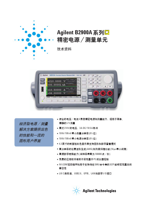
脉冲宽度 50 µs ~ 99999.9 s 50 µs ~ 99999.9 s 50 µs ~ 99999.9 s
50 µs ~ 2.5 ms 50 µs ~ 10 ms 50 µs ~ 1 ms
最大占空比 99.9999 % 99.9999 % 99.9999 % 2.5 % 2.5 % 2.5 %
最大电压和电流
直流或脉冲 1 仅脉冲 1
最大电压 210 V 21 V 6V 200 V 6V
最大电流
0.105 A 1.515 A2 3.03 A2 1.515 A 10.5 A
电流 [A]
电流 [A]
电压 [V]
电压 [V]
直流或脉冲 1
仅脉冲 1
1. 在“脉冲源补充特征”中查看“最大脉冲宽度和占空比”以了解适宜的最大电压和电流。 2. 最大电流限制 : 对于 21 V/I.5I5 A 和 6 V/3.03 A 两种量程,使用双通道时,最大电流以下表中的数值为限。
仅使用单通道时,最大电流没有限制。
最大电流限制
通道 1 电压 ± (0 V< V ≤6 V) ± (0 V< V ≤6 V) ± (6 V < V ≤ 21 V) ± (6 V < V ≤ 21 V)
通道 2 电压 ± (0 V < V ≤ 6 V) ± (6 V < V ≤ 21 V) ± (0 V < V ≤ 6 V) ± (6 V < V ≤ 21 V)
噪声 10 Hz ~ 20 MHz ( 电压源 ): 3 mVrms, 20 V 量程。 电压源过冲 :
< ± (0.1 % + 10 mV)。 步进为量程的 10 % ~ 90 %, 电阻负载。 电流源过冲 :
安捷伦E4991A(射频阻抗、材料分析仪)替代:4291A
图 7. 分段扫描列表
可以使用多种测量夹具
图 7-1. 用分段扫描方法得到的测量结果
保存测量结果和数据
● 内置 3.5 英寸软盘驱动器,内置硬盘。 ● 可以保存 VBA 程序,校准数据, 测量结果的数据。 ● 对于使用自动化工具的用户,支持 CITIFILE 格式的数据。
网络接口
● 控制其它仪表或简化共享数据的过程。 ● 使用异地用户接口软件 与 PC 相连接。
图 1. 片状电感的 Ls-Q 特性的测量结果 表 2. Q 值的测量精度 (典型值)
Q 值测量精度
测量频率
表 3. E4991A 和网路分析仪的各项关键特性的比较
E4991A
网络分析仪
测量的器件的类型 1 端口器件, 例如电感器、 电容器, 以及其它器件
2 端口器件, 例如滤波器、 放大器, 以及其它器件
图 5. 使用 16200B 直流偏置适配器扩展 E4991A 的 直流偏置范围
提取器件的等效电路参数
E 4 9 9 1 A 的 等 效 电 路 分 析 功 能 比起标准的两参数模型来能给工程 师们提供更为详细的电路模型。 E4991A 提供了 5 种不同类型的多参 数模型来满足对不同类型的器件 — 例如陶瓷电容器或晶体谐振器等 — 进行分析的需要。您可以根据等效 参数值通过仿真得出一个阻抗轨 迹,然后把仿真结果与实际测量得 到的轨迹进行对比。所提取的参数 还可以应用到自动电路设计 (EDA) 工 具中来提高器件建模的精确度。
对于应用于移动通信设备中的 器件来说,他们的品质因数 (Q 值)和 等效串联电阻 (ESR) 都是极为重要的 参数,测量这两个参数需要极高的 精度。在安捷伦推出 E4991A 之前, 在 2 GHz 以上的测量频率范围内一直 没有一个很好解决方案。用 E4991A 测量 Q 值和 ESR 比起用传统的矢量网 络分析仪测量精度大有提高,这是 因为 E4991A 采用了增强型的 RF I-V 测 量技术来测量被测器件 (DUT) 的电压 和电流,同时还采用了使用 小损耗 电容器对夹具误差进行校准的创新 技术。
- 1、下载文档前请自行甄别文档内容的完整性,平台不提供额外的编辑、内容补充、找答案等附加服务。
- 2、"仅部分预览"的文档,不可在线预览部分如存在完整性等问题,可反馈申请退款(可完整预览的文档不适用该条件!)。
- 3、如文档侵犯您的权益,请联系客服反馈,我们会尽快为您处理(人工客服工作时间:9:00-18:30)。
E4991B 操作 – 保存数据
是德科技(中国)有限公司 以是为本 以德致远 专注测量75载
1/15/2016
Page 25
16092A SMD 夹具补偿开路/ 短路
Open 开路
是德科技(中国)有限公司 以是为本 以德致远 专注测量75载
Short 短路
1/15/2016
Page 26
E4991B/ 16092A 磁芯阻抗测量
是德科技(中国)有限公司 以是为本 以德致远 专注测量75载
1/14/2016
Page 5
Keysight 16192A SMD 夹具
是德科技(中国)有限公司 以是为本 以德致远 专注测量75载
1/14/2016
Page 6
Keysight 16196C SMD 夹具
是德科技(中国)有限公司 以是为本 以德致远 专注测量75载
1/15/2016
Page 41
16196C SMD 夹具, 补偿开路/ 短路标准件
Open Short 开路 短路
是德科技(中国)有限公司 以是为本 以德致远 专注测量75载
1/15/2016
Page 42
16196C SMD 夹具 – 开路补偿
Fit the cap in place with the mark toward the front, and turn it to the right until it is locked.
Page 9
Keysight 16197A SMD 夹具
是德科技(中国)有限公司 以是为本 以德致远 专注测量75载
1/14/2016
Page 10
E4991B/ 16092A/ 16192A/ 16196C/ 16197A SMD 夹具
是德科技(中国)有限公司 以是为本 以德致远 专注测量75载
E4991B/ 16192A 0805 SMD 电感测量 – 2.2uH
L C R |Z|
是德科技(中国)有限公司 以是为本 以德致远 专注测量75载
1/15/2016
Page 40
E4991B/ 16192A 0805 SMD 电感测量 – 2.2uH
L
是德科技(中国)有限公司 以是为本 以德致远 专注测量75载
选择测试参数,设置测试频率、电平等。
对校准和夹具补偿进行设置 进行 Open/ Short/ Load/ Low-Loss C 校准 进行 Open/ Short 补偿 进行测试,根据需要显示测量结果
是德科技(中国)有限公司 以是为本 以德致远 专注测量75载
1/15/2016
Page 13
E4991B 测量设定
1/15/2016
Page 20
E4991B 校准 – APC7 同轴测试接口
Open 开路
Short 短路
Load 负载
Low Loss C 空气电容
1/15/2016
是德科技(中国)有限公司 以是为本 以德致远 专注测量75载
Page 21
E4991B 夹具补偿 - 开路/ 短路
是德科技(中国)有限公司 以是为本 以德致远 专注测量75载
Hale Waihona Puke 1/15/2016Page 22
E4991B 操作 – 保存/ 调用设定
是德科技(中国)有限公司 以是为本 以德致远 专注测量75载
1/15/2016
Page 23
E4991B 操作 – 保存/ 调用设定
是德科技(中国)有限公司 以是为本 以德致远 专注测量75载
1/15/2016
Page 24
是德科技(中国)有限公司 以是为本 以德致远 专注测量75载
1/15/2016
Page 44
16196C SMD 夹具 – 把 SMD 器件 垂直放进孔内
Fit the cap in place with the mark toward the front, and turn it to the right until it is locked.
1/14/2016
Page 16
E4991B 夹具定义选择和设定
16092A 16192A 16197A 16196C
是德科技(中国)有限公司 以是为本 以德致远 专注测量75载
1/14/2016
Page 17
E4991B 校准 – APC7 同轴测试接口
16195A
是德科技(中国)有限公司 以是为本 以德致远 专注测量75载
1/15/2016
Page 29
E4991B/ 16092A 磁芯阻抗测量 - |Z|
是德科技(中国)有限公司 以是为本 以德致远 专注测量75载
1/15/2016
Page 30
E4991B/ 16092A 磁芯电感测量 - LS
是德科技(中国)有限公司 以是为本 以德致远 专注测量75载
1/15/2016
0402 0603 0805 1206
Open 开路
是德科技(中国)有限公司 以是为本 以德致远 专注测量75载
Short 短路
1/15/2016
Page 53
E4991B/ 16197A 0402 SMD 电阻测量 – 30mOhm
是德科技(中国)有限公司 以是为本 以德致远 专注测量75载
1/15/2016
1/15/2016
Page 56
其他 E4991B 实用功能 – 对数幅度
是德科技(中国)有限公司 以是为本 以德致远 专注测量75载
1/15/2016
Page 57
其他 E4991B 实用功能 – 自动缩放所有迹线
自动缩放 所有迹线 把所有迹线 放在显示图 的中间
是德科技(中国)有限公司 以是为本 以德致远 专注测量75载
1/15/2016
Page 18
16195A 校准标准件
Open 开路
Short 短路
是德科技(中国)有限公司 以是为本 以德致远 专注测量75载
Load 负载
Low Loss C 空气电容
1/15/2016
Page 19
E4991B 校准 – APC7 同轴测试接口
是德科技(中国)有限公司 以是为本 以德致远 专注测量75载
频率 点数/ 扫频
平均
对数扫频
是德科技(中国)有限公司 以是为本 以德致远 专注测量75载
1/14/2016
Page 14
E4991B 测量设定
显示
标记
标记寻索
是德科技(中国)有限公司 以是为本 以德致远 专注测量75载
1/14/2016
Page 15
E4991B 测量设定 – 迹线参数
参数
是德科技(中国)有限公司 以是为本 以德致远 专注测量75载
Page 31
E4991B/ 16092A 磁芯阻抗测量
比较不同 磁芯阻抗 值 |Z|
是德科技(中国)有限公司 以是为本 以德致远 专注测量75载
1/15/2016
Page 32
E4991B/ 16092A 磁芯阻抗测量数据
是德科技(中国)有限公司 以是为本 以德致远 专注测量75载
1/15/2016
1/14/2016
Page 7
Keysight 16196C SMD 夹具电极结构
是德科技(中国)有限公司 以是为本 以德致远 专注测量75载
1/14/2016
Page 8
Keysight 16196C SMD 夹具部件
是德科技(中国)有限公司 以是为本 以德致远 专注测量75载
1/14/2016
1/15/2016
Page 58
其他 E4991B 实用功能 – 分析
极限测试 等效电路
公式编辑
是德科技(中国)有限公司 以是为本 以德致远 专注测量75载
E4991B 阻抗分析仪 1MHz – 3GHz 与 16092A/ 16192A/ 16196C/ 16197A SMD 夹具 阻抗测量
January 14, 2016
是德科技(中国)有限公司 以是为本 以德致远 专注测量75载
E4991B 精密 阻抗分析仪 前面板
是德科技(中国)有限公司 以是为本 以德致远 专注测量75载
L C R |Z|
是德科技(中国)有限公司 以是为本 以德致远 专注测量75载
1/15/2016
Page 47
E4991B/ 16196C 0201 SMD 电容测量 – 0.5pF
L C R |Z|
是德科技(中国)有限公司 以是为本 以德致远 专注测量75载
1/15/2016
Page 48
E4991B/ 16196C 0201 SMD 电容测量 – 0.5pF
1/14/2016
Page 2
E4991B 精密 阻抗分析仪
是德科技(中国)有限公司 以是为本 以德致远 专注测量75载
1/14/2016
Page 3
E4991B 精密 阻抗分析仪 – 技术指标
是德科技(中国)有限公司 以是为本 以德致远 专注测量75载
1/14/2016
Page 4
Keysight 16092A SMD 夹具
16192A SMD 夹具补偿开路/ 短路块
Open
是德科技(中国)有限公司 以是为本 以德致远 专注测量75载
Short
1/15/2016
Page 38
E4991B/ 16192A 0805 SMD 2.2uH
是德科技(中国)有限公司 以是为本 以德致远 专注测量75载
1/14/2016
Page 39
是德科技(中国)有限公司 以是为本 以德致远 专注测量75载