(完整word)红外遥控协议分析之:NEC协议
nec协议

竭诚为您提供优质文档/双击可除nec协议篇一:necprotocolnec协议necprotocoltomyknowledgetheprotocolidescribeherewasdevelopedby nec.iveseenverysimilarprotocoldescriptionsontheinte rnet,andtheretheprotocoliscalledjapaneseFormat.idoadmitthatidontknowexactlywhodevelopedit.whatidok nowisthatitisusedinmylateVcRproducedbysanyoandwasma rketedunderthenameofFisher.necmanufacturedtheremote controlic.thisdescriptionwastakenfromtheVcRsservicemanual.tho sewerethedays,whenservicemanualswerefulledwithusefu linformation!Features8bitaddressand8bitcommandlengthaddressandcommandare transmittedtwiceforreliabilitypulsedistancemodulati oncarrierfrequencyof38khzbittimeof1.125msor2.25ms modulationthenecprotocolusespulsedistanceencodingpulseisofathebits.each560μslong38khzcarrierburst(about21cycles).alogical"1"ta kes2.25mstotransmit,whilealogical"0"isonlyhalfoftha t,being1.125ms.therecommendedcarrierduty-cycleis1/4 or1/3.protocolthepictureaboveshowsatypicalpulsetrainofthenecproto col.withthisprotocolthelsbistransmittedfirst.inthis caseaddress$59andcommand$16istransmitted.amessageisstartedbya9msagcburst,whichwasusedtosetth egainoftheearlieriRreceivers.thisagcburstisthenfoll owedbya4.5msspace,whichisthenfollowedbytheaddressan dcommand.addressandcommandaretransmittedtwice.these condtimeallbitsareinvertedandcanbeusedforverificati onofthereceivedmessage.thetotaltransmissiontimeisco nstantbecauseeverybitisrepeatedwithitsinvertedlengt h.ifyourenotinterestedinthisreliabilityyoucanignore theinvertedvalues,oryoucanexpandtheaddressandcomman dto16bitseach!acommandistransmittedonlyonce,evenwhenthekeyonthere motecontrolremainspressed.every110msarepeatcodeistr ansmittedforaslongasthekeyremainsdown.thisrepeatcod eissimplya9msagcpulsefollowedbya2.25msspaceanda560μsburst.extendednecprotocolthenecprotocolissowidelyusedthatsoonallpossibleaddr esseswereusedup.bysacrificingtheaddressredundancyth eaddressrangewasextendedfrom256possiblevaluestoappr oximately65000differentvalues.thiswaytheaddressrang ewasextendedfrom8bitsto16bitswithoutchanginganyothe rpropertyoftheprotocol.thecommandredundancyisstillp reserved.thereforeeachaddresscanstillhandle 256differentcommands.keepinmindthat256addressvaluesoftheextendedprotocol areinvalidbecausetheyareinfactnormalnecprotocoladdr esses.wheneverthelowbyteistheexactinverseofthehighb yteitisnotavalidextendedaddress.externallinksexamplecommandsthetablebelowliststhemessagessentbytheremotecontrol ofmylateFisher530VcR(itserveduswellduringits20years longlife).篇二:红外遥控协议分析之:nec协议红外遥控编码传输协议生产厂家对红外遥控的编码做了严格的规范,目前国内外主流的红外遥控编码传输协议有十多种,如nec、philipsRc-5、philipsRc-6、philipsRc-mm、philipsRecs80、Rca、x-sat、itt、jVc、sharp、nokianRc17和sonysiRc等。
红外遥控原理与nec协议介绍

红外遥控原理与nec协议介绍
红外遥控原理与NEC协议介绍
在现代家居中,我们经常使用的电器设备多数都配备了红外遥控功能,这是一种非常方便的控制方式,它使得我们可以在不接触设备的情况下,方便地控制它们的开关、调节等操作。
那么,红外遥控是如何实现的呢?NEC协议又是什么?
红外遥控原理
红外遥控所用的信号是红外线,光波的频率高于红外线的频率,因此红外线是我们肉眼无法看到的。
当我们按下遥控器上的按钮后,遥控器内部的红外LED会发出一个特定频率的光波,这个光波会通过空气传递到电器设备中的红外接收器(IR Receiver)。
红外接收器会将接
收到的光波转化为电信号,并将其传递给设备的中央处理器,中央处理器便会根据接收到的电信号执行相应的操作。
NEC协议介绍
NEC是红外遥控信号最为常用的协议之一,它是由日本NEC公司开发的。
NEC协议采用了脉冲编码调制技术(Pulse Coded Modulation, PCM),将发送的数据进行脉冲编码,以使接收端可以正确地解码。
NEC
协议的传输速率为38kHz,每个数据包由4个字节组成,其中第一个字节表示设备地址,第二个字节表示设备地址的反码,第三个字节表示数据码,第四个字节表示数据码的反码。
NEC协议可以支持多达256个设备地址,因此可以同时控制多个设备。
总结
红外遥控技术在现代家居中得到广泛应用,它是一种方便、快捷的控制方式,使得我们可以在不接触设备的情况下控制它们。
NEC协议是红外遥控信号最为常用的协议之一,它采用了脉冲编码调制技术,能够支持多达256个设备地址,因此能够满足多设备控制的需求。
红外 协议
红外协议红外协议是一种应用于红外通信的通信规约,用于红外遥控和红外通讯等场景中。
红外协议主要分为红外遥控协议和红外通信协议两部分。
红外遥控协议是指将遥控设备发送的红外信号编码成特定的协议格式,经过红外传感器接收并解码后,再由目标设备根据协议规则执行相应的操作。
常见的红外遥控协议有NEC、RC-5、RC-6等。
NEC红外协议是一种最常见的红外遥控协议,通常用于电视遥控器、空调遥控器等。
NEC协议通过调制红外载频信号来表示数字信号。
每个数字信号由9ms的起始位和4.5ms的起始位隔开,然后由16位地址码、16位数据码和8位反码构成。
地址码用于区分不同的遥控器设备,数据码表示遥控器键值。
接收设备在解码后,通过判断地址码和数据码来判断是哪个键被按下。
RC-5红外协议也是一种常见的红外遥控协议,常用于DVD遥控器、音响遥控器等家电设备中。
RC-5协议将每个红外信号分为两个连续的半周期。
每个半周期由1.778ms的载频信号和1.778ms的无载频信号组成。
一个完整的信号由13位二进制数据构成,其中1位为起始位,5位为地址码,6位为命令码,1位为反码。
接收设备通过解码操作,根据地址码和命令码执行相应的功能。
RC-6红外协议是RC-5的升级版,具有更高的功能扩展性和更低的误码率。
RC-6协议将红外信号延长到2.667ms的载频信号和2.667ms的无载频信号。
一个完整的信号由20位二进制数据构成,其中1位为起始位,2位为系统码,5位为地址码,8位为命令码,1位为反码,3位为扩展码。
接收设备在解码后,根据地址码和命令码进行区分和执行命令。
红外通信协议是指将红外信号用于设备之间的通讯,实现数据的传输和交互。
常用的红外通信协议有IrDA(红外数据通信协议)和红外遥测通信协议。
IrDA红外通信协议是一种用于近距离高速红外通信的协议。
它采用了扩频技术和差分编码技术,能够在红外载频信号中传输数字数据。
IrDA协议规定了通信双方的通信速率、数据格式、时序等参数,保证了数据的可靠传输和解码。
常用红外遥控协议

常用红外遥控协议一、NEC协议NEC ProtocolTo my knowledge the protocol I describe here was developed by NEC. I've seen very similar protocol descriptions on the internet, and there the protocol is called Japanese Format.I do admit that I don't know exactly who developed it. What I do know is that it is used in my late VCR produced by Sanyo and was marketed under the name of Fisher. NEC manufactured the remote control IC.This description was taken from the VCR's service manual. Those were the days, when service manuals were fulled with useful information!Features•8 bit address and 8 bit command length•Address and command are transmitted twice for reliability•Pulse distance modulation•Carrier frequency of 38kHz•Bit time of 1.125ms or 2.25msModulationThe NEC protocol uses pulse distance encoding of the bits. Each pulse is a 560µs long 38kHz carrier burst (about 21 cycles). A logical "1" takes 2.25ms to transmit, while a logical "0" is only half of that, being 1.125ms. The recommended carrier duty-cycle is 1/4 or 1/3.ProtocolThe picture above shows a typical pulse train of the NEC protocol. With this protocol the LSB is transmitted first. In this case Address $59 and Command $16 is transmitted. A message is started by a 9ms AGC burst, which was used to set the gain of the earlier IR receivers. This AGC burst is then followed by a 4.5ms space, which is then followed by the Address and Command. Address and Command are transmitted twice. The second time all bits are inverted and can be used for verification of the received message. The total transmission time is constant because every bit is repeated with its inverted length. If you're not interested in this reliability you can ignore the inverted values, or you can expand the Address and Command to 16 bits each!A command is transmitted only once, even when the key on the remote control remains pressed. Every 110ms a repeat code is transmitted for as long as the key remains down. This repeat code is simply a 9ms AGC pulse followed by a 2.25ms space and a 560µs burst.Extended NEC protocolThe NEC protocol is so widely used that soon all possible addresses were used up. By sacrificing the address redundancy the address range was extended from 256 possible values to approximately 65000 different values. This way the address range was extended from 8 bits to 16 bits without changing any other property of the protocol.The command redundancy is still preserved. Therefore each address can still handle 256 different commands.Keep in mind that 256 address values of the extended protocol are invalid because they are in fact normal NEC protocol addresses. Whenever the low byte is the exact inverse of the high byte it is not a valid extended address.二、RC5遥控协议Philips RC-5 ProtocolThe RC-5 code from Philips is possibly the most used protocol by hobbyists, probably because of the wide availability of cheap remote controls.The protocol is well defined for different device types ensuring compatibility with your whole entertainment system. Lately Philips started using a new protocol called RC-6 which has more features.Features• 5 bit address and 6 bit command length (7 command bits for RC5X)•Bi-phase coding (aka Manchester coding)•Carrier frequency of 36kHz•Constant bit time of 1.778ms (64 cycles of 36 kHz)ModulationThe protocol uses bi-phase modulation (or so-called Manchester coding) of a 36kHz IR carrier frequency. All bits are of equal length of 1.778ms in this protocol, with half of the bit time filled with a burst of the 36kHz carrier and the other half being idle. A logical zerois represented by a burst in the first half of the bit time. A logical one is represented by a burst in the second half of the bit time. The pulse/pause ratio of the 36kHz carrier frequency is 1/3 or 1/4 which reduces power consumption.ProtocolThe drawing below shows a typical pulse train of an RC-5 message. This example transmits command $35 to address $05.The first two pulses are the start pulses, and are both logical "1". Please note that half a bit time is elapsed before the receiver will notice the real start of the message. Extended RC-5 uses only one start bit. Bit S2 is transformed to command bit 6, providing for a total of 7 command bits. The value of S2 must be inverted to get the 7th command bit though!The 3rd bit is a toggle bit. This bit is inverted every time a key is released and pressed again. This way the receiver can distinguish between a key that remains down, or is pressed repeatedly.The next 5 bits represent the IR device address, which is sent with MSB first. The address is followed by a 6 bit command, again sent with MSB first.A message consists of a total of 14 bits, which adds up to a total duration of 25 ms. Sometimes a message may appear to be shorter because the first half of the start bit S1 remains idle. And if the last bit of the message is a logic "0" the last half bit of the message is idle too.As long as a key remains down the message will be repeated every 114ms. The toggle bit will retain the same logical level during all of these repeated messages. It is up to the receiver software to interpret this auto repeat feature.三、RC6遥控协议Philips RC-6 ProtocolRC-6 is, as may be expected, the successor of the RC-5 protocol. Like RC-5 the new RC-6 protocol was also defined by Philips. It is a very versatile and well defined protocol.Because of this versatility its original definition is many pages long. Here on my page I will only summarize the most important properties of this protocol.Features•Different modes of operation, depending on the intended use•Dedicated Philips modes and OEM modes•Variable command length, depending on the operation mode•Bi-phase coding (aka Manchester coding)•Carrier frequency of 36kHz•Manufacturer PhilipsModulationRC-6 signals are modulated on a 36 kHz Infra Red carrier. The duty cycle of this carrier has to be between 25% and 50%.Data is modulated using Manchester coding. This means that each bit (or symbol) will have both a mark and space in the output signal. If the symbol is a "1" the first half of the bit time is a mark and the second half is a space. If the symbol is a "0" the first half of the bit time is a space and the second half is a mark.Please note that this is the opposite of the RC-5 protocol!The main timing unit is 1t, which is 16 times the carrier period (1/36k * 16 = 444µs). With RC-6 a total of 5 different symbols are defined:•The leader pulse, which has a mark time of 6t (2.666ms) and a space time of 2t(0.889ms). This leader pulse is normally used to set the gain of the IR receiver unit.•Normal bits, which have a mark time of 1t (0.444ms) and space time of 1t(0.444ms). A "0" and "1" are encoded by the position of the mark and space in thebit time.•Trailer bits, which have a mark time of 2t (0.889ms) and a space time of 2t(0.889ms). Again a "0" and "1" are encoded by the position of the mark and spacein the bit time.The leader and trailer symbols are only used in the header field of the messages, which will be explained in more detail below.RC-6 Mode 0I can only describe operation mode 0 because I have never actually seen other modes in use than the one my Philips TV understands. The way I understand it the other modes can vary extremely from mode 0.Mode 0 is a dedicated Philips Consumer Electronics mode. It allows control of up to 256 independent devices, with a total of 256 commands per device.The command is a concatenation of different information. I will cover these different components from left to right.Header fieldThe Header field consists of 3 different components.•First the leader symbol LS is transmitted. Its purpose is to adjust the gain of the IR receiving unit.•This leader symbol is followed by a start bit SB which always has the value "1".Its purpose is to calibrate the receiver's timing.•The mode bits mb2 ... mb0 determine the mode, which is 0 in this case, thus all three bits will be "0".•Finally the header is terminated by the trailer bit TR. Please note that the bit time of this symbol is twice as long as normal bits! This bit also serves as thetraditional toggle bit, which will be inverted whenever a key is released. Thisallows the receiver to distinguish between a new key or a repeated key.Control FieldThis field holds 8 bits which are used as address byte. This means that a total of 256 different devices can be controlled using mode 0 of RC-6.The msb is transmitted first.Information FieldThe information field holds 8 bits which are used as command byte. This means that each device can have up to 256 different commands.The msb is transmitted first.Signal Free TimeThe Signal Free time is a period in which no data may be transmitted (by any device). It is important for the receiver to detect the signal free time at the end of a message to avoid incorrect reception.The signal free time is set to 6t, which is 2.666ms.四、天威定义遥控协议1、数据格式如下:2、电平定义:3、载波定义:4、说明:引导码+设备码+键码+循环延时引导码= 3640us (高电平)+ 1800us(低电平)设备码= 32位:格式:用户码0(T)8位+ 用户码1(W)8位+ 用户码2(S)8位+ 用户码3(X)8位键码= 16位:格式:数据码0(8位)+数据码1(8位)“0”= 380us (高电平)+ 380us(低电平)“1”= 380us (高电平)+ 1350us(低电平)循环延时=50ms误差:5%“高电平”为红外线载波调制,“低电平”为无红外线载波调制五、Sharp协议Sharp ProtocolI only have little information on this protocol. It is used in VCRs that are produced by Sharp, that is why I gave it the name Sharp protocol.Features•8 bit command, 5 bit address length•Pulse distance modulation•Carrier frequency of 38kHz•Bit time of 1ms or 2msModulationThe Sharp protocol uses a pulse distance encoding of the bits. Each pulse is a 320µs long 38kHz carrier burst (about 12 cycles). A logical "1" takes 2ms to transmit, while a logical "0" is only 1ms. The recommended carrier duty-cycle is 1/4 or 1/3.ProtocolIn the picture above you see a typical pulse train sending the command $11 and address $03. The Address is sent first and consists of 5 bits. Next comes the 8 bit command. In both cases the LSB of the data is sent first.I don't exactly know the purpose of the Expansion and Check bits that follow the command. Both bits were fixed in the example that I had at hand.I can only guess that the Check bit is used to find out whether we are receiving a normal or inverted message.One complete command sequence consist of 2 messages. The first transmission is exactly as described above. The second transmission follows the first one after a delay of 40ms, and basically contains the same information. The only difference is that all bits, except those from the address field, are inverted. This way the receiver can verify if the received message is reliable or not.。
红外遥控协议_红外编解码彻底解析

10
buf1=RECEIVE;
//
}
else{
switch(state1){
case 10:sbuf2=sbuf1>>4;
//
sbuf2=~sbuf2;
//
if((sbuf2&0x0f)!=(sbuf1&0x0f)) //
{
//
if(sbuf1==TAIL)
//
{
//
buf1=RECEIVE; //
“1”
0.56ms,
1.
9ms
4.5ms
0.52ms, 0.68ms
4.5ms 1.04ms
“0”
64 128
“0” “1”
PWM 64 128?
2
MCS-51 CPU CPU
500ms
CPU microchip pic16
128
PWM
120ms “”
winbond w741 1us
holtek ht48 256
void send_ack_iic(void);
void send_nack_iic(void);
bit receive_ack_iic(void);
void start_iic(void);
void stop_iic(void);
void write_key_data(unsigned char a);
static unsigned char sbuf1,sbuf2,rsbuf1,rsbuf2; //sbuf1,sbuf2
rsbuf1,rsbuf2
EA="0";
//
if(RI){
RI="0";
NEC协议的红外遥控程序(任意IO口)
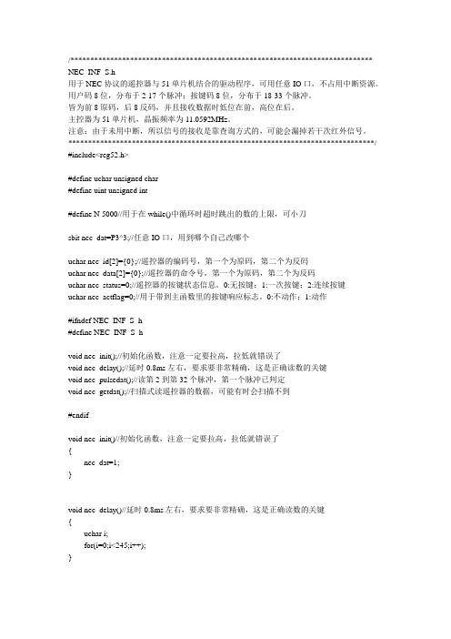
/**************************************************************************** NEC_INF_S.h用于NEC协议的遥控器与51单片机结合的驱动程序,可用任意IO口,不占用中断资源。
用户码8位,分布于2-17个脉冲;按键码8位,分布于18-33个脉冲。
皆为前8原码,后8反码,并且接收数据时低位在前,高位在后。
主控器为51单片机,晶振频率为11.0592MHz。
注意:由于未用中断,所以信号的接收是靠查询方式的,可能会漏掉若干次红外信号。
*****************************************************************************/ #include<reg52.h>#define uchar unsigned char#define uint unsigned int#define N 5000//用于在while()中循环时超时跳出的数的上限,可小刀sbit nec_dat=P3^3;//任意IO口,用到哪个自己改哪个uchar nec_id[2]={0};//遥控器的编码号,第一个为原码,第二个为反码uchar nec_data[2]={0};//遥控器的命令号,第一个为原码,第二个为反码uchar nec_status=0;//遥控器的按键状态信息。
0:无按键;1:一次按键;2:连续按键uchar nec_actflag=0;//用于带到主函数里的按键响应标志。
0:不动作;1:动作#ifndef NEC_INF_S_h#define NEC_INF_S_hvoid nec_init();//初始化函数,注意一定要拉高,拉低就错误了void nec_delay();//延时0.8ms左右,要求要非常精确,这是正确读数的关键void nec_pulsedat();//读第2到第32个脉冲,第一个脉冲已判定void nec_getdat();//扫描式读遥控器的数据,可能有时会扫描不到#endifvoid nec_init()//初始化函数,注意一定要拉高,拉低就错误了{nec_dat=1;}void nec_delay()//延时0.8ms左右,要求要非常精确,这是正确读数的关键{uchar i;for(i=0;i<245;i++);}/*void nec_act()//按键响应程序,根据自己需要写{nec_getdat();//先扫描一遍红外信号if(nec_actflag==1)//如果是正确的红外信号才处理,否则跳过{if(nec_data[0]==~nec_data[1])//验证所接收数据是否正确{switch(nec_data[0])//自己写所需要的程序段{case 69:/*点亮二极管,让蜂鸣器发声,什么都行,写在这里*/ break;case 70: /*以下都一样,对应的遥控器按键见图1-1*/ break;case 71: break;case 68:break;case 64:break;case 67:break;case 7:break;case 21:break;case 9:break;case 22:break;case 25:break;case 13:break;case 12:break;case 24:break;case 94:break;case 8:break;case 28:break;case 90:break;case 66:break;case 82:break;case 74:break;}}nec_actflag=0;}}*/void nec_pulsedat()//读第2到第32个脉冲,第一个脉冲已判定{uchar i=0;uint num=0;for(i=1;i<32;i++){num=0;while((nec_dat==0)&&(num<N))num++;nec_delay();{if((i>=1)&&(i<=7))nec_id[0]=nec_id[0]|(0x01<<i);if((i>=8)&&(i<=15))nec_id[1]=nec_id[1]|(0x01<<(i-8));if((i>=16)&&(i<=23))nec_data[0]=nec_data[0]|(0x01<<(i-16));if((i>=24)&&(i<=31))nec_data[1]=nec_data[1]|(0x01<<(i-24));num=0;while((nec_dat==1)&&(num<N))num++;}else{if((i>=1)&&(i<=7))nec_id[0]=nec_id[0]&(~(0x01<<i));if((i>=8)&&(i<=15))nec_id[1]=nec_id[1]&(~(0x01<<i-8));if((i>=16)&&(i<=23))nec_data[0]=nec_data[0]&(~(0x01<<i-16));if((i>=24)&&(i<=31))nec_data[1]=nec_data[1]&(~(0x01<<i-24));}}}void nec_getdat()//扫描式读遥控器的数据,可能有时会扫描不到{uint num=0;if(nec_dat==1){num=0;while((nec_dat==1)&&(num<N))num++;}nec_delay();if(nec_dat==0){nec_delay();if(nec_dat==0){nec_delay();if(nec_dat==0){nec_delay();if(nec_dat==0){nec_status=1;num=0;while((nec_dat==0)&&(num<N))num++;num=0;while((nec_dat==1)&&(num<N))num++;}}}}if(nec_status==1){num=0;while((nec_dat==0)&&(num<N))num++;if(nec_dat==1){nec_delay();nec_delay();nec_delay();if(nec_dat==1)nec_status=2;else{nec_id[0]=0x01;nec_pulsedat();}}else{nec_id[0]=0x00;nec_pulsedat();}nec_actflag=1;//一次按键的响应程序}if(nec_status==2){//持续按键的响应程序}nec_status=0;//必须归零,非常重要}图1-1 红外遥控器按键对应的接收码图1-2 本程序使用的遥控器注意:本程序适用于NEC协议的红外遥控器,但是每一款遥控器的按键码可能不同,需要自己找到自己手头上遥控器的按键码资料来对程序进行改动。
nec遥控协议

原码,第二个为反码
ucharnec_status=0;//遥控器的按键状态信息。0:无按
键;1:一次按键;2:连续按键
ucharnec_actflag=0;//用于带到主函数里的按键响应
标志。0:不动作;1:动作
#ifndefnec_inF_s_h
#definenec_inF_s_h
voidnec_init();//初始化函数,注意一定要拉高,拉
就错误了
(
nec_dat=1;
}
voidnec_delay()//延时0.8ms左右,要求要非常精确,
这是正确读数的关键
(
uchari;
for(i=0;i }
/*voidnec_act()//按键响应程序,根据自己需要写
(
nec_getdat() ; //先扫描一遍红外信号
if(nec_actflag==1)//如果是正确的红外信号才处理,
(
num=0;while((nec_dat==0)
if(nec_dat==1)
(
nec_delay();nec_delay();nec_delay();
if(nec_dat==1)nec_status=2;
else
(
nec_id[0]=0x01;
nec红外协议

nec红外协议NEC红外协议。
NEC红外协议是一种用于红外遥控器通信的协议标准,广泛应用于家电、电子设备等领域。
它采用了38kHz的载波频率,通过调制不同的脉宽来实现数据的传输,具有传输距离远、抗干扰能力强等优点。
本文将对NEC红外协议的原理、格式、编码方式等进行详细介绍,以便对该协议有更深入的了解。
NEC红外协议的原理是通过调制38kHz的载波信号来传输数据。
在NEC协议中,逻辑“0”和逻辑“1”分别用不同的脉宽来表示,通常逻辑“0”用560us的脉宽表示,而逻辑“1”用1690us的脉宽表示。
通过这种方式,接收端可以根据脉宽的不同来解析出发送端发送的数据,从而实现通信的目的。
NEC红外协议的格式通常包括引导脉冲、地址码、反码、命令码等部分。
其中,引导脉冲是一个9ms的高电平脉冲和4.5ms的低电平脉冲交替组成,用于唤醒接收器;地址码用来表示遥控器的地址信息;反码是地址码的反码,用于提高数据传输的可靠性;命令码用来表示具体的操作命令,比如开关机、音量调节等。
通过这样的格式组织,NEC红外协议可以实现对各种遥控器指令的准确传输。
NEC红外协议的编码方式是采用了32位的编码格式,其中包括8位的地址码、8位的地址反码、8位的命令码和8位的命令反码。
这种编码方式可以保证数据的准确性和可靠性,同时也便于接收端对数据进行解析和识别。
通过这种编码方式,NEC红外协议可以实现对各种遥控器指令的精准传输。
总的来说,NEC红外协议作为一种广泛应用的红外遥控器通信协议,具有传输距离远、抗干扰能力强、编码方式简单等优点。
通过对NEC红外协议的原理、格式、编码方式等方面的介绍,相信读者对该协议有了更深入的了解,可以更好地应用于实际的产品开发和设计中。
总结一下,NEC红外协议在红外遥控器通信领域有着重要的地位,其原理简单明了,格式清晰规范,编码方式可靠性高。
相信随着科技的不断发展,NEC红外协议将会有更广泛的应用和发展。
- 1、下载文档前请自行甄别文档内容的完整性,平台不提供额外的编辑、内容补充、找答案等附加服务。
- 2、"仅部分预览"的文档,不可在线预览部分如存在完整性等问题,可反馈申请退款(可完整预览的文档不适用该条件!)。
- 3、如文档侵犯您的权益,请联系客服反馈,我们会尽快为您处理(人工客服工作时间:9:00-18:30)。
红外遥控编码传输协议
生产厂家对红外遥控的编码做了严格的规范,目前国内外主流的红外遥控编码传输协议有十多种,如NEC、Philips RC-5、Philips RC-6、Philips RC-MM、Philips RECS80、 RCA、X-Sat、ITT、JVC、Sharp、Nokia NRC17和Sony SIRC等。
国内最常用的规范有两种:NEC和Sony SIRC。
这两种规范的调制方式分别为:PPM(脉冲间隔调制)和PWM(脉冲宽度调制)。
谈到这两个概念,我需要具体讲解一下,因为我在网上查阅相关资料时甚是郁闷,好多说法相互矛盾。
有说NEC属于PWM的因为它的脉宽不同,PPM的脉宽是固定的。
而细心地朋友如果探究到NEC的典型芯片的芯片手册时,会发现上面这种说法是错误的。
比如UPD6121这款红外远程控制芯片的调制方式为PPM。
后来终于在一家国外的网站上找到了能够自圆其说的解释。
个人认为比较正确,拿来和大家分享。
要想认清红外遥控编码传输协议的具体内容,我想还是先捡其重点来讲一下,编码规范中最重要的当属调制这部分了。
而主流的调制方式有两种分别为PPM和PWM,当然其他还有好几种,这里先不讲解,免得糊涂了。
本文就先介绍下PPM和PWM的区别。
PPM(Pulse Position Modulation),其实更加准确的说法应该是PDM(Pulse Distance Modulation)即脉冲间隔调制:
上图为典型编码规范NEC协议的调制图,为PPM调制。
可以看出不管是“0”还是“1”,有高频调制波的地方(下文称其为脉冲)其宽度都是相同的位560us,而脉冲间的间隔则是不同的:“1”时为(2.25ms-560us),“0”时为(1.12ms-560us)。
由此得来PPM的称号。
再来看下PWM的调制波形吧:
显然可以看出,“1”的脉冲宽度为1.2ms,“0”的为600us。
而脉冲间隔不管是“0”还是“1”,均为600us。
从而PPM和PWM的两个概念认识清楚!当然不同规范中PPM和PWM 这两种调制方式的脉宽及脉冲间隔可能不同,上面两个图只是示例而已。
红外遥控协议分析之:NEC协议
NEC协议特点:
8位地址和8位命令,为提高可靠性,地址和命令都分别传输2次,第2次为反码传输
脉冲间隔调制:38kHz载波频率
每一位时间为1.12ms(0)或2.25ms(1)
调制采用脉冲间隔时间调制每一位。
每一个脉冲都是560uS长度的38kHz载波脉冲,占空比为1/4或1/3(约21个周期)。
逻辑1:2.25ms 逻辑0:1.12ms
上图是NEC协议的一个典型脉冲发送图。
此协议LSB最低位先传送。
例子:
此图传送的地址是$59、命令是$16。
一个信息发送是由9ms的AGC自动增益控制脉冲开头,在早期的IR红外接收器中用来设置增益。
接着是4.5ms空闲,然后是地址、命令。
地址和命令都传送2次,第二次的地址和命令是反码,可以用来校验接收到的信息。
总的传输时间是固定的,因为每一位都有反码传送。
如果遥控器上的按键一直按着,这个命令也只发送一次,但是会每110ms发送一次重复码,直到遥控器按键释放。
重复码比较简单:一个9mS的AGC脉冲、2.25mS间隔、560uS 脉冲:
整体效果:。