机械外文翻译中英文
机械工程外文翻译(适用于毕业论文外文翻译+中英文对照)
Mechanical engineering1.The porfile of mechanical engineeringEngingeering is a branch of mechanical engineerig,itstudies mechanical and power generation especially power and movement.2.The history of mechanical engineering18th century later periods,the steam engine invention hasprovided a main power fountainhead for the industrialrevolution,enormously impelled each kind of mechznicalbiting.Thus,an important branch of a newEngineering –separated from the civil engineering tools andmachines on the branch-developed together with Birmingham andthe establishment of the Associantion of Mechanical Engineersin 1847 had been officially recognized.The mechanicalengineering already mainly used in by trial and error methodmechanic application technological development into professional engineer the scientific method of which in theresearch,the design and the realm of production used .From themost broad perspective,thedemend continuously to enhance theefficiencey of mechanical engineers improve the quality of work,and asked him to accept the history of the high degreeof education and training.Machine operation to stress not only economic but also infrastructure costs to an absolute minimun.3.The field of mechanical engineeringThe commodity machinery development in the develop country,in the high level material life very great degree is decided each kind of which can realize in the mechanical engineering.Mechanical engineers unceasingly will invent the machine next life to produce the commodity,unceasingly will develop the accuracy and the complexity more and more high machine tools produces the machine.The main clues of the mechanical development is:In order to enhance the excellent in quality and reasonable in price produce to increase the precision as well as to reduce the production cost.This three requirements promoted the complex control system development.The most successful machine manufacture is its machine and the control system close fusion,whether such control system is essentially mechanical or electronic.The modernized car engin production transmission line(conveyer belt)is a series of complex productions craft mechanization very good example.The people are in the process of development in order to enable further automation of the production machinery ,the use of a computer to store and handle largevolumes of data,the data is a multifunctional machine tools necessary for the production of spare parts.One of the objectives is to fully automated production workshop,threerotation,but only one officer per day to operate.The development of production for mechanical machinery must have adequate power supply.Steam engine first provided the heat to generate power using practical methods in the old human,wind and hydropower,an increase of engin .New mechanical engineering industry is one of the challenges faced by the initial increase thermal effciency and power,which is as big steam turbine and the development of joint steam boilers basically achieved.20th century,turbine generators to provide impetus has been sustained and rapid growth,while thermal efficiency is steady growth,and large power plants per kW capital consumption is also declining.Finally,mechanical engineers have nuclear energy.This requires the application of nuclear energy particularly high reliability and security, which requires solving many new rge power plants and the nuclear power plant control systems have become highly complex electroonics,fluid,electricity,water and mechanical parts networks All in all areas related to the mechanical engineers.Small internal combustion engine,both to the type(petrol and diesel machines)or rotary-type(gas turbines and Mong Kerr machine),as well as their broad application in the field of transport should also due to mechanical enginerrs.Throughout the transport,both in the air and space,or in the terrestrial and marine,mechanial engineers created a variety of equipment and power devices to their increasing cooperation with electrical engineers,especially in the development of appropration control systems.Mechanical engineers in the development of military weapons technology and civil war ,needs a similar,though its purpose is to enhance rather than destroy their productivity.However.War needs a lot of resources to make the area of techonlogy,many have a far-reaching development in peacetime efficiency.Jet aircraft and nuclear reactors are well known examples.The Biological engineering,mechanical engineering biotechnology is a relatively new and different areas,it provides for the replacement of the machine or increase the body functions as well as for medical equipment.Artficial limbs have been developed and have such a strong movement and touch response function of the human body.In the development of artificial organ transplant is rapid,complex cardiac machines and similar equipment to enable increasingly complexsurgery,and injuries and ill patients life functions can be sustained.Someenviromental control mechanical engineers through the initial efforts to drainage or irrigation pumping to the land and to mine and ventilation to control the human environment.Modern refrigeration and air-conditioning plant commonaly used reverse heat engine,where the heat from the engine from cold places to more external heat.Many mechanical engineering products,as well as other leading technology development city have side effects on the environment,producingnoise,water and air pollution caused,destroyed land and landscape.Improve productivity and diver too fast in the commodity,that the renewable natural forces keep pace.For mechanical engineers and others,environmental control is rapidly developing area,which includes a possible development and production of small quantities of pollutants machine sequnce,and the development of new equipment and teachnology has been to reduce and eliminate pollution.4.The role of mechanical engineeringThere are four generic mechanical engineers in common to the above all domains function.The 1st function is the understanding and the research mechanical sciencefoundation.It includes the power and movement of the relationship dynamics For example,in the vibration and movement of the relationship;Automaticcontrol;Study of the various forms of heart,energy,power relations between the thermodynamic;Fluidflows; Heat transfer; Lubricant;And material properties.The 2nd function will be conducts the research,thedesing and the development,this function in turn attempts to carry on the essential change to satisfy current and the future needs.This not only calls for a clear understanding of mechanical science,and have to break down into basic elements of a complex system capacity.But also the need for synthetic and innovative inventions.The 3rd function is produces the product and the power,includeplan,operation and maintenance.Its goal lies in the maintenance either enhances the enterprise or the organization longer-tern and survivabilaty prestige at the same time,produces the greatest value by the least investments and the consumption.The 4th function is mechanical engineer’s coordinated function,including the management,theconsultation,as well as carries on the market marking in certain situation.In all these function,one kind unceasingly to use thescience for a long time the method,but is not traditional or the intuition method tendency,this is a mechanical engineering skill aspect which unceasingly grows.These new rationalization means typical names include:The operations research,the engineering economics,the logical law problem analysis(is called PABLA) However,creativity is not rationalization.As in other areas,in mechanicalengineering, to take unexpected and important way to bring about a new capacity,still has a personal,markedcharacteristice.5.The design of mechanical engineeringThe design of mechanical is the design has the mechanical property the thing or the system,suchas:the instrument and the measuring appliance in very many situations,the machine design must use the knowledge of discipline the and so on mathematics,materials science and mechanics.Mechanical engineering desginincludeing all mechanical desgin,but it was a study,because it also includes all the branches of mechsnicalengineering,such as thermodynamics all hydrodynamics in the basic disciplines needed,in the mechanical engineering design of the initial stude or mechanical design.Designstages.The entire desgin process from start to finish,in the process,a demand that is designed forit and decided to do the start.After a lot of repetition,the final meet this demand by the end of the design procees and the plan.Designconsiderations.Sometimes in a system is to decide which parts needs intensity parts of geometric shapes and size an important factor in this context that we must consider that the intensity is an important factor in the design.When we use expression design considerations,we design parts that may affect the entire system design features.In the circumstances specified in the design,usually for a series of such functions must be taken into account.Howeever,to correct purposes,we should recognize that,in many cases the design of important design considerations are not calculated or test can determine the components or systems.Especiallystudents,wheen in need to make important decisions in the design and conduct of any operation that can not be the case,they are often confused.These are not special,they occur every day,imagine,forexample,a medical laboratory in the mechanical design,from marketing perspective,people have high expectations from the strength and relevance of impression.Thick,and heavy parts installed together:to produce a solid impression machines.And sometimes machinery and spare parts from the design style is the point and not theother point of view.Our purpose is to make those you do not be misled to believe that every design decision will need reasonable mathematical methods.Manufacturing refers to the raw meterials into finished products in the enterprise.Create three distinct phases.Theyare:input,processingexprot.The first phase includes the production of all products in line with market needs essential.First there must be the demand for the product,the necessary materials,while also needs such as energy,time,human knowledge and technology resourcess . Finall,the need for funds to obtain all the other resources. Lose one stage after the second phase of the resources of the processes to be distributed.Processing of raw materials into finished products of these processes.To complete the design,based on the design,and then develop plans.Plan implemented through various production processes.Management of resources and processes to ensure efficiency and productivity.Forexample,we must carefully manage resources to ensure proper use of funds.Finally,people are talking about the product market was cast.Stage is the final stage of exporting finished or stage.Once finished just purchased,it must be delivered to the users.According to productperformance,installation and may have to conduct further debugging in addition,someproducts,especially those very complex products User training is necessary.6.The processes of materials and maunfacturingHere said engineering materials into two main categories:metals and non-ferrous,high-performance alloys and power metals.Non-metallic futher divided into plastice,syntheticrubber,composite materials and ceramics.It said the production proccess is divided into several major process,includingshape,forging,casting/founding,heattreatment,fixed/connections ,measurement/ quality control and materalcutting.These processes can be further divide into each other’s craft.Various stages of the development of the manufacturing industry Over the years,the manufacturing process has four distinct stages of development, despite the overlap.These stages are:The first phase is artisanal,the second Phase is mechanization.The third phase is automation the forth Phase is integrated.When mankind initial processing of raw materials into finished products will be,they use manual processes.Each with their hands and what are the tools manusllyproduced.This is totally integrated production take shape.A person needsindentification,collectionmaterials,the design of a product to meet that demand,the production of such products and use it.From beginning to end,everything is focused on doing the work of the human ter in the industrial revolution introduced mechanized production process,people began to use machines to complete the work accomplished previously manual. This led to the specialization.Specialization in turn reduce the manufacture of integrated factors.In this stage of development,manufacturing workers can see their production as a whole represent a specific piece of the part of the production process.Onecan not say that their work is how to cope with the entire production process,or how they were loaded onto a production of parts finished.Development of manufacting processes is the next phase of the selection process automation.This is a computer-controlled machinery and processes.At this stage,automation island began to emerge in the workshop lane.Each island represents a clear production process or a group of processes.Although these automated isolated island within the island did raise the productivity of indivdualprocesses,but the overall productivity are often not change.This is because the island is not caught in other automated production process middle,but not synchronous withthem .The ultimate result is the efficient working fast parked through automated processes,but is part of the stagnation in wages down,causingbottlenecks.To better understand this problem,you can imagine the traffic in the peak driving a red light from the red Service Department to the next scene. Occasionally you will find a lot less cars,more than being slow-moving vehicles,but the results can be found by the next red light Brance.In short you real effect was to accelerate the speed of a red Department obstruction offset.If you and other drivers can change your speed and red light simultaneously.Will advance faster.Then,all cars will be consistent,sommthoperation,the final everyone forward faster.In the workshop where the demand for stable synchronization of streamlined production,and promoted integration of manufacturing development.This is a still evolving technology.Fully integrated in the circumstances,is a computer-controllrd machinery and processing.integrated is completed through computer.For example in the preceding paragraph simulation problems,the computer will allow all road vehicles compatible with the change in red.So that everyone can steady traffic.Scientific analysis of movement,timing and mechanics ofthe disciplines is that it is composed of two pater:statics and dynamics.Statics analyzed static system that is in the system,the time is not taken into account,research and analysis over time and dynamics of the system change.Dynameics from the two componets.Euler in 1775 will be the first time two different branches: Rigid body movement studies can conveniently divided into two parts:geometric and mechanics.The first part is without taking into account the reasons for the downward movement study rigid body from a designated location to another point of the movement,and must use the formula to reflect the actual,the formula would determine the rigid body every point position. Therefore,this study only on the geometry and,morespecifically,on the entities from excision.Obviously,the first part of the school and was part of a mechanical separation from the principles of dynamics to study movement,which is more than the two parts together into a lot easier.Dynamics of the two parts are subsequently divided into two separate disciplines,kinematic and dynamics,a study of movement and the movement strength.Therefore,the primary issue is the design of mechanical systems understand its kinematic.Kinematic studies movement,rather than a study ofits impact.In a more precise kinematic studies position,displacement,rotation, speed,velocity and acceleration of disciplines,foresample,or planets orbiting research campaing is a paradigm.In the above quotation content should be pay attention that the content of the Euler dynamics into kinematic and rigid body dynamics is based on the assumption that they are based on research.In this very important basis to allow for the treatment of two separate disciplines.For soft body,soft body shape and even their own soft objects in the campaign depends on the role of power in their possession.In such cases,should also study the power and movement,and therefore to a large extent the analysis of the increased complexity.Fortunately, despite the real machine parts may be involved are more or less the design of machines,usually with heavy material designed to bend down to the lowest parts.Therefore,when the kinematic analysis of the performance of machines,it is often assumed that bend is negligible,spare parts are hard,but when the load is known,in the end analysis engine,re-engineering parts to confirm this assnmption.机械工程1.机械工程简介机械工程是工程学的一个分支,它研究机械和动力的产,尤其是力和动力。
机械外文翻译中英文
英文资料Limits and TolerancesThe breakage of the machine spare parts ,generally always from the surface layer beginning of .The function of the product ,particularly its credibility and durable ,be decided by the quantity of spare parts surface layer to a large extent. Purpose that studies the machine to process the surface quantity be for control the machine process medium various craft factor to process the surface quantity influence of regulation, in order to make use of these regulations to control to process the process, end attain to improve the surface quantity, the exaltation product use the function of purpose .The machine processes the surface quantity to use the influence of the function to the machine(A) The surface quantity to bear to whet the sexual influence1.Rough degree of surface to bear to whet the sexual influenceA just process vice-of two contact surfaces of good friction, the first stage is rough only in the surface of the peak department contact ,the actual contact area is much smaller than theoretical contact area, in contact with each other the peak of the units have very great stress, to produce actual contact with the surface area of plastic deformation, deformation and peak between the Department of shear failure, causing serious wear.Parts wear may generally be divided into three stages, the initial stage of wear and tear, normal wear and tear all of a sudden intense phase of stage wear.Parts of the surface roughness of the surface wear big impact. In general the smaller the value of surface roughness, wear better. However, surface roughness value is too small, lubricants difficult to store, contact between the adhesive-prone elements, wear it to increase. Therefore, the surface roughness of a best value, the value and parts of the work related to increased work load, the initial wear increased, the best rough surface is also increased.2.Cold Working hardening the surface of the wear resistanceProcessing the Cold Work hardening the surface of the friction surface layer of metal microhardness increase, it will generally improve the wear resistance. Cold Working but not a higher degree of hardening, wear resistance for the better, because too much will lead to hardening of the Cold Working excessive loose organization ofmetal, even a crack and peeling off the surface of the metal, declined to wear resistance.(B)The surface quality of the impact of fatigue strengthMetal hand alternating loads of fatigue after the damage occurred in parts often Chilled layer below the surface and, therefore parts of the surface quality of fatigue very influential.1.Surface roughness on the impact of fatigue strengthIn alternating load, the surface roughness of the Au-site easily lead to stress concentration, a fatigue crack, the higher the value of surface roughness, surface traces of Yu Shen Wen, Wen at the end of the radius smaller, anti-fatigue damage at the end of the more capacity Worse.2.Residual stress, fatigue Cold Work hardening of the impactResidual stress on the impact of large parts fatigue. Surface layer of residual stress fatigue crack will expand and accelerate the fatigue damage the surface layer and the residual stress can prevent fatigue crack growth, delaying the formation of fatigue damage.(C)The surface quality of the corrosion resistance of the impactParts of the corrosion resistance to a large extent depends on the surface roughness. The higher the value of surface roughness, Au Valley accumulate on the more corrosive substances. Corrosion resistance of the more worse.Surface layer of residual stress will produce stress corrosion cracking, lower parts of the wear-resistance, and the residual stress is to prevent stress corrosion cracking.(D) The surface quality with qualityRough surface will affect the value of the size of the co-ordination with the surface quality. The gap with rough value will increase wear and tear, increased space, with the requirements of the destruction of nature. For Fit, the assembly part of the process of convex surface-crowded peak times, the actual reduction of the surplus and reduce the support of the connection between the strength.DimensioningThe design of a machine includes many factors other than those of determining the loads and stresses and selecting the proper materials. Before construction or manufacture can begin, it is necessary to have complete assembly and detail drawings to convey all necessary information to the shop men. The designer frequently is called upon to check the drawings before they are sent to the shop. Much experience andfamiliarity with manufacturing processes are needed before one can become conversant with all phases of production drawings.Drawings should be carefully checked to see that the dimensioning is done in a manner that will be most convenient and understandable to the production departments. It is obvious that a drawing should be made in such a way that it has one and only one interpretation. In particular, shop personnel should not be required to make trigonometric or other involved calculations before the production machines can be set up.Dimensioning is an involved subject and long experience is required for its mastery.Tolerances must be placed on the dimensions of a drawing to limit the permissible variations in size because it is impossible to manufacture a part exactly to a given dimension. Although small tolerances give higher quality work and a better operating mechanism, the cost of manufacture increases rapidly as the tolerances are reduced, as indicated by the typical curve of Fig 14.1. It is therefore important that the tolerances be specified at the largest values that the operating or functional considerations permit.Tolerances may be either unilateral or bilateral. In unilateral dimensioning, one tolerance is zero, and all the variations are given by the other tolerance. In bilateral dimensioning, a mean dimension is used which extends to the midpoint of the tolerance zone with equal plus and minus variations extending each way from this dimension.The development of production processes for large-volume manufacture at low cost has been largely dependent upon interchangeability of component parts. Thus the designer must determine both the proper tolerances for the individual parts, The manner of placing tolerances on drawings depends somewhat on the kind of product or type of manufacturing process. If the tolerance on a dimension is not specifically stated, the drawing should contain a blanket note which gives the value of the tolerance for such dimensions. However, some companies do not use blanket notes on the supposition that if each dimension is considered individually, wider tolerance than those called for in the note could probably be specified. In any event it is very important that a drawing be free from ambiguities and be subject only to a single interpretation.Dimension and ToleranceIn dimensioning a drawing, the numbers placed in the dimension lines represent dimension that are only approximate and do not represent any degree of accuracy unless so stated by the designer.To specify a degree of accuracy, it is necessary to add tolerance figures to the dimension. Tolerance is the amount of variation permitted in the part or the total variation allowed in a given dimension. A shaft might have a nominal size of 2.5 in. (63.5mm), but for practical reasons this figure could not be maintained in manufacturing without great cost. Hence, a certain tolerance would be added and , if a variation of ±0.003 in.(±0.08mm) could be permitted, the dimension would be stated 2.500±0.003(63.5±0.008mm).Dimensions given close tolerances mean that the part must fit properly with some other part. Both must be given tolerances in keeping with the allowance desired, the manufacturing processes available, and the minimum cost of production and assembly that will maximize profit. Generally speaking, the cost of a part goes up as the tolerance is decreased. If a part has several or more surfaces to be machined, the cost can be excessive when little deviation is allowed from the nominal size.Allowance, which is sometimes confused with tolerance, has an altogether different meaning.It is the minimum clearance space intended between mating parts and representsthe condition of tightest permissible fit. If a shaft, size 1.4980.0000.003+-, is to fit a hole ofsize 1.5000.0030.000+-, the minimum size hole is 1.500 and the maximum size shaft is 1.498.Thus the allowance is 0.002 and the maximum clearance is 0.008 as based on the minimum shaft size and maximum hole dimension.Tolerances may be either unilateral or bilateral. Unilateral tolerance means that any variation is made in only one direction from the nominal or basic dimension.Referring to the previous example, the hole is dimensioned 1.5000.0030.000+-, whichrepresents a unilateral tolerance. If the dimensions were given as 1.500±0.003, the tolerance would be bilateral; that is , it would vary both over and under the nominal dimension. The unilateral system permits changing the tolerance while still retaining the same allowance or type of fit. With the bilateral system, this is not possible without also changing the nominal size dimension of one or both of the two mating parts. In mass production, where mating parts must be interchangeable, unilateral tolerances are customary. To have an interference or fore fit between mating parts, the tolerances must be such as to create a zero or negative allowance.Tolerances Limits and FitsThe drawing must be a true and complete statement of the designer’s expr essed in such a way that the part is convenient to manufacture. Every dimension necessary to define the product must be stated once and repeated in different views. Dimensions relating to one particular feature, such as the position and size of hole, where possible, appear on the same view.There should be no more dimensions than are absolutely necessary, and no feature should be located by more than one dimension in any direction. It may be necessary occasionally to give an auxiliary dimension for reference, possibly for inspection. When this is so, the dimension should be enclosed in a bracket and marked for reference. Such dimensions are not governed by general tolerances.Dimensions that affect the function of the part should always be specified and not left as the sum or other dimensions. If this is not done, the total permissible variation on that dimension will form the sum or difference of the other dimensions and their tolerance, and this with result in these tolerances having to be made unnecessarily tight. The overall dimension should always appear.All dimensions must be governed by the general tolerance on the drawing unless otherwise stated. Usually, such a tolerance will be governed by the magnitude of the dimension. Specific tolerances must always be stated on dimensions affecting or interchangeability.A system of tolerances is necessary to allow for the variations in accuracy that are bound to occur during manufacture, and still provide for interchangeability and correct function of the part.A tolerance is the difference in a dimension in order to allow for unavoidable imperfections in workmanship. The tolerance range will depend on the accuracy of the manufacturing organization, the machining process and the magnitude of the dimension. The greater the tolerance range is disposed on both sides of the nominal dimension. A unilateral tolerance is one where the tolerance zone is on one side only of the nominal dimension, in which case the nominal dimension may from one of the limits.Limits are the extreme dimensions of the tolerance zone. For example, nominal dimension30mm tolerance 30.0230.000++ limits 30.02530.000Fits depend on the relationship between the tolerance zones of two mating parts,and may be broadly classified into a clearance fit with positive allowance, a transition fit where the allowance may be either positive or negative (clearance or interference) , an interference fit where the allowance is always negative.Type of Limits and FitsThe ISO system of Limits and Fits, widely used in a number of leading metric countries, is considerably more complex than the ANSI system.In this system, each part has a basic size. Each limit of part, high and sign being obtained by subtracting the basic size form the limit in question. The difference between the two limits of size of a part is called the tolerance, an absolute without sign.There are three classes of fits: 1) clearance fits, 2) transition fits ( the assembly may have either clearance or interference ), and 3) interference fits .Either a shaft-basis system or a hole-basis system may be used. For any given basic size, a range of tolerance and deviations may be specified with respect to be line of zero deviation, called the zero line. The tolerance is a function of the basic size and is designated by a number symbol, called the grade-thus the tolerance grade. The position of the tolerance with respect to the zero line also a function of the basic size-is indicated by a letter symbol(or two letter), a capital letter for holes and a lowercase letter for shafts. Thus the specification for a hole and shaft having a basic size of 45mm might be45H8/g7.Twenty standard grades of tolerance are provided, called IT 01,IT 0 ,IT 1-18, providing numerical values for each nominal diameter, in arbitrary steps up to 500mm (for example 0-3,3-6,6-10…, 400-500mm). The value of the tolerance unit, I, for grades 5-16 is=+0.0.001i DWhere i is in microns and D in millimeters.Standard shaft and hole deviations similarly are provided by sets of formulas, However, for practical, both tolerances and deviations are provided in three sets of rather complex tables. Additional tables gives the values for basic sizes above 500mm and for “Commonly Used Shafts and Holes” in two categories ---“General Purpose” and “Fine Mecbanisms and Horology”.中文翻译极限与误差机械零件的破坏,一般总是从表层开始的。
机械类外文文献及翻译
机械类外文文献及翻译(文档含中英文对照即英文原文和中文翻译)原文:GEAR AND SHAFT INTRODUCTIONAbstract:The important position of the wheel gear and shaft can't falter in traditional machine and modern machines.The wheel gear and shafts mainly install the direction that delivers the dint at the principal axis box. The passing to process to make them can is divided into many model numbers, using for many situations respectively. So we must be the multilayers to the understanding of the wheel gear and shaft in many ways .Key words: Wheel gear; ShaftIn the force analysis of spur gears, the forces are assumed to act in a single plane. We shall study gears in which the forces have three dimensions. The reason for this, in the case of helical gears, is that the teeth are not parallel to the axis of rotation. And in the case ofbevel gears, the rotational axes are not parallel to each other. There are also other reasons, as we shall learn.Helical gears are used to transmit motion between parallel shafts. The helix angle is the same on each gear, but one gear must have a right-hand helix and the other a left-hand helix. The shape of the tooth is an involute helicoid. If a piece of paper cut in the shape of a parallelogram is wrapped around a cylinder, the angular edge of the paper becomes a helix. If we unwind this paper, each point on the angular edge generates an involute curve. The surface obtained when every point on the edge generates an involute is called an involute helicoid.The initial contact of spur-gear teeth is a line extending all the way across the face of the tooth. The initial contact of helical gear teeth is a point, which changes into a line as the teeth come into more engagement. In spur gears the line of contact is parallel to the axis of the rotation; in helical gears, the line is diagonal across the face of the tooth. It is this gradual of the teeth and the smooth transfer of load from one tooth to another, which give helical gears the ability to transmit heavy loads at high speeds. Helical gears subject the shaft bearings to both radial and thrust loads. When the thrust loads become high or are objectionable for other reasons, it may be desirable to use double helical gears. A double helical gear (herringbone) is equivalent to two helical gears of opposite hand, mounted side by side on the same shaft. They develop opposite thrust reactions and thus cancel out the thrust load. When two or more single helical gears are mounted on the same shaft, the hand of the gears should be selected so as to produce the minimum thrust load.Crossed-helical, or spiral, gears are those in which the shaft centerlines are neither parallel nor intersecting. The teeth of crossed-helical fears have point contact with each other, which changes to line contact as the gears wear in. For this reason they will carry out very small loads and are mainly for instrumental applications, and are definitely not recommended for use in the transmission of power. There is on difference between a crossed heli : cal gear and a helical gear until they are mounted in mesh with each other. They are manufactured in the same way. A pair of meshed crossed helical gears usually have the same hand; that is ,a right-hand driver goes with a right-hand driven. In the design of crossed-helical gears, the minimum sliding velocity is obtained when the helix angle areequal. However, when the helix angle are not equal, the gear with the larger helix angle should be used as the driver if both gears have the same hand.Worm gears are similar to crossed helical gears. The pinion or worm has a small number of teeth, usually one to four, and since they completely wrap around the pitch cylinder they are called threads. Its mating gear is called a worm gear, which is not a true helical gear. A worm and worm gear are used to provide a high angular-velocity reduction between nonintersecting shafts which are usually at right angle. The worm gear is not a helical gear because its face is made concave to fit the curvature of the worm in order to provide line contact instead of point contact. However, a disadvantage of worm gearing is the high sliding velocities across the teeth, the same as with crossed helical gears.Worm gearing are either single or double enveloping. A single-enveloping gearing is onein which the gear wraps around or partially encloses the worm.. A gearing in which each element partially encloses the other is, of course, a double-enveloping worm gearing. The important difference between the two is that area contact exists between the teeth of double-enveloping gears while only line contact between those of single-enveloping gears. The worm and worm gear of a set have the same hand of helix as for crossed helical gears, but the helix angles are usually quite different. The helix angle on the worm is generally quite large, and that on the gear very small. Because of this, it is usual to specify the lead angle on the worm, which is the complement of the worm helix angle, and the helix angle on the gear; the two angles are equal for a 0-deg. Shaft angle.When gears are to be used to transmit motion between intersecting shaft, some of bevel gear is required. Although bevel gear are usually made for a shaft angle of 0 deg. They may be produced for almost any shaft angle. The teeth may be cast, milled, or generated. Only the generated teeth may be classed as accurate. In a typical bevel gear mounting, one of the gear is often mounted outboard of the bearing. This means that shaft deflection can be more pronounced and have a greater effect on the contact of teeth. Another difficulty, which occurs in predicting the stress in bevel-gear teeth, is the fact the teeth are tapered.Straight bevel gears are easy to design and simple to manufacture and give very good results in service if they are mounted accurately and positively. As in the case of squr gears, however, they become noisy at higher values of the pitch-line velocity. In these cases it is often go : od design practice to go to the spiral bevel gear, which is the bevel counterpart of thehelical gear. As in the case of helical gears, spiral bevel gears give a much smoother tooth action than straight bevel gears, and hence are useful where high speed are encountered.It is frequently desirable, as in the case of automotive differential applications, to have gearing similar to bevel gears but with the shaft offset. Such gears are called hypoid gears because their pitch surfaces are hyperboloids of revolution. The tooth action between such gears is a combination of rolling and sliding along a straight line and has much in common with that of worm gears.A shaft is a rotating or stationary member, usually of circular cross section, having mounted upon it such elementsas gears, pulleys, flywheels, cranks, sprockets, and other power-transmission elements. Shaft may be subjected to bending, tension, compression, or torsional loads, acting singly or in combination with one another. When they are combined, one may expect to find both static and fatigue strength to be important design considerations, since a single shaft may be subjected to static stresses, completely reversed, and repeated stresses, all acting at the same time.The word “shaft” covers numerous v ariations, such as axles and spindles. Anaxle is a shaft, wither stationary or rotating, nor subjected to torsion load. A shirt rotating shaft is often called a spindle.When either the lateral or the torsional deflection of a shaft must be held to close limits, the shaft must be sized on the basis of deflection before analyzing the stresses. The reason for this is that, if the shaft is made stiff enough so that the deflection is not too large, it is probable that the resulting stresses will be safe. But by no means should the designer assume that they are safe; it is almost always necessary to calculate them so that he knows they are within acceptable limits. Whenever possible, the power-transmission elements, such as gears or pullets, should be located close to the supporting bearings, This reduces the bending moment, and hence the deflection and bending stress.Although the von Mises-Hencky-Goodman method is difficult to use in design of shaft, it probably comes closest to predicting actual failure. Thus it is a good way of checking a shaft that has already been designed or of discovering why a particular shaft has failed in service. Furthermore, there are a considerable number of shaft-design problems in which the dimension are pretty well limited by other considerations, such as rigidity, and it is only necessary for the designer to discover something about the fillet sizes, heat-treatment,and surface finish and whether or not shot peening is necessary in order to achieve the required life and reliability.Because of the similarity of their functions, clutches and brakes are treated together. In a simplified dynamic representation of a friction clutch, or brake, two in : ertias I and I traveling at the respective angular velocities W and W, one of which may be zero in the case of brake, are to be brought to the same speed by engaging the clutch or brake. Slippage occurs because the two elements are running at different speeds and energy is dissipated during actuation, resulting in a temperature rise. In analyzing the performance of these devices we shall be interested in the actuating force, the torque transmitted, the energy loss and the temperature rise. The torque transmitted is related to the actuating force, the coefficient of friction, and the geometry of the clutch or brake. This is problem in static, which will have to be studied separately for eath geometric configuration. However, temperature rise is related to energy loss and can be studied without regard to the type of brake or clutch because the geometry of interest is the heat-dissipating surfaces. The various types of clutches and brakes may be classified as fllows:. Rim type with internally expanding shoes. Rim type with externally contracting shoes. Band type. Disk or axial type. Cone type. Miscellaneous typeThe analysis of all type of friction clutches and brakes use the same general procedure. The following step are necessary:. Assume or determine the distribution of pressure on the frictional surfaces.. Find a relation between the maximum pressure and the pressure at any point. Apply the condition of statical equilibrium to find (a) the actuating force, (b) the torque, and (c) the support reactions.Miscellaneous clutches include several types, such as the positive-contact clutches, overload-release clutches, overrunning clutches, magnetic fluid clutches, and others.A positive-contact clutch consists of a shift lever and two jaws. The greatest differences between the various types of positive clutches are concerned with the design of the jaws. To provide a longer period of time for shift action during engagement, the jaws may be ratchet-shaped, or gear-tooth-shaped. Sometimes a great many teeth or jaws are used, and they may be cut either circumferentially, so that they engage by cylindrical mating, or on the faces of the mating elements.Although positive clutches are not used to the extent of the frictional-contact type, they do have important applications where synchronous operation is required.Devices such as linear drives or motor-operated screw drivers must run to definite limit and then come to a stop. An overload-release type of clutch is required for these applications. These clutches are usually spring-loaded so as to release at a predetermined toque. The clicking sound which is heard when the overload point is reached is considered to be a desirable signal.An overrunning clutch or coupling permits the driven member of a machine to “freewheel” or “overrun” bec ause the driver is stopped or because another source of power increase the speed of the driven. This : type of clutch usually uses rollers or balls mounted between an outer sleeve and an inner member having flats machined around the periphery. Driving action is obtained by wedging the rollers between the sleeve and the flats. The clutch is therefore equivalent to a pawl and ratchet with an infinite number of teeth.Magnetic fluid clutch or brake is a relatively new development which has two parallel magnetic plates. Between these plates is a lubricated magnetic powder mixture. An electromagnetic coil is inserted somewhere in the magnetic circuit. By varying the excitation to this coil, the shearing strength of the magnetic fluid mixture may be accurately controlled. Thus any condition from a full slip to a frozen lockup may be obtained.齿轮和轴的介绍摘要:在传统机械和现代机械中齿轮和轴的重要地位是不可动摇的。
机械专业中英文对照翻译大全171页word
机械专业英语词汇中英文对照翻译一览表陶瓷 ceramics合成纤维 synthetic fibre 电化学腐蚀 electrochemical corrosion车架 automotive chassis悬架 suspension转向器 redirector变速器 speed changer板料冲压 sheet metal parts孔加工 spot facing machining车间 workshop工程技术人员 engineer气动夹紧 pneuma lock数学模型 mathematical model画法几何 descriptive geometry机械制图 Mechanical drawing投影 projection视图 view剖视图 profile chart标准件 standard component零件图 part drawing装配图 assembly drawing尺寸标注 size marking技术要求 technical requirements刚度 rigidity内力 internal force位移 displacement截面 section疲劳极限 fatigue limit断裂 fracture塑性变形 plastic distortion脆性材料 brittleness material刚度准则 rigidity criterion垫圈 washer垫片 spacer直齿圆柱齿轮 straight toothed spur gear 斜齿圆柱齿轮 helical-spur gear直齿锥齿轮 straight bevel gear运动简图 kinematic sketch齿轮齿条 pinion and rack蜗杆蜗轮 worm and worm gear虚约束 passive constraint曲柄 crank摇杆 racker凸轮 cams共轭曲线 conjugate curve范成法 generation method定义域 definitional domain值域 range导数\\微分 differential coefficient求导 derivation定积分 definite integral不定积分 indefinite integral曲率 curvature偏微分 partial differential毛坯 rough游标卡尺 slide caliper千分尺 micrometer calipers攻丝 tap二阶行列式 second order determinant 逆矩阵 inverse matrix线性方程组 linear equations概率 probability随机变量 random variable排列组合 permutation and combination 气体状态方程 equation of state of gas动能 kinetic energy势能 potential energy机械能守恒 conservation of mechanical energy动量 momentum桁架 truss轴线 axes余子式 cofactor逻辑电路 logic circuit触发器 flip-flop脉冲波形 pulse shape数模 digital analogy液压传动机构 fluid drive mechanism机械零件 mechanical parts淬火冷却 quench淬火 hardening回火 tempering调质 hardening and tempering磨粒 abrasive grain结合剂 bonding agent砂轮 grinding wheel后角 clearance angle龙门刨削 planing主轴 spindle主轴箱 headstock卡盘 chuck加工中心 machining center车刀 lathe tool车床 lathe钻削镗削 bore车削 turning磨床 grinder基准 benchmark钳工 locksmith锻 forge压模 stamping焊 weld拉床 broaching machine拉孔 broaching装配 assembling铸造 found流体动力学 fluid dynamics流体力学 fluid mechanics加工 machining液压 hydraulic pressure切线 tangent机电一体化 mechanotronics mechanical-electrical integration气压 air pressure pneumatic pressure稳定性 stability介质 medium液压驱动泵 fluid clutch液压泵 hydraulic pump阀门 valve失效 invalidation强度 intensity载荷 load应力 stress安全系数 safty factor可靠性 reliability螺纹 thread螺旋 helix键 spline销 pin滚动轴承 rolling bearing滑动轴承 sliding bearing弹簧 spring制动器 arrester brake十字结联轴节 crosshead联轴器 coupling链 chain皮带 strap精加工 finish machining粗加工 rough machining变速箱体 gearbox casing腐蚀 rust氧化 oxidation磨损 wear耐用度 durability随机信号 random signal离散信号 discrete signal超声传感器 ultrasonic sensor 集成电路 integrate circuit 挡板 orifice plate残余应力 residual stress套筒 sleeve扭力 torsion冷加工 cold machining电动机 electromotor汽缸 cylinder过盈配合 interference fit热加工 hotwork摄像头 CCD camera倒角 rounding chamfer优化设计 optimal design工业造型设计 industrial moulding design有限元 finite element滚齿 hobbing插齿 gear shaping伺服电机 actuating motor铣床 milling machine钻床 drill machine镗床 boring machine步进电机 stepper motor丝杠 screw rod导轨 lead rail组件 subassembly可编程序逻辑控制器 Programmable Logic Controller PLC 电火花加工 electric spark machining电火花线切割加工 electrical discharge wire - cutting相图 phase diagram热处理 heat treatment固态相变 solid state phase changes有色金属 nonferrous metal陶瓷 ceramics合成纤维 synthetic fibre电化学腐蚀 electrochemical corrosion车架 automotive chassis悬架 suspension转向器 redirector变速器 speed changer板料冲压 sheet metal parts孔加工 spot facing machining车间 workshop工程技术人员 engineer气动夹紧 pneuma lock数学模型 mathematical model画法几何 descriptive geometry机械制图 Mechanical drawing投影 projection视图 view剖视图 profile chart标准件 standard component零件图 part drawing装配图 assembly drawing尺寸标注 size marking技术要求 technical requirements刚度 rigidity内力 internal force位移 displacement截面 section疲劳极限 fatigue limit断裂 fracture塑性变形 plastic distortion脆性材料 brittleness material刚度准则 rigidity criterion垫圈 washer垫片 spacer直齿圆柱齿轮 straight toothed spur gear 斜齿圆柱齿轮 helical-spur gear直齿锥齿轮 straight bevel gear运动简图 kinematic sketch齿轮齿条 pinion and rack蜗杆蜗轮 worm and worm gear虚约束 passive constraint曲柄 crank摇杆 racker凸轮 cams共轭曲线 conjugate curve范成法 generation method定义域 definitional domain值域 range导数\\微分 differential coefficient 求导 derivation定积分 definite integral不定积分 indefinite integral曲率 curvature偏微分 partial differential毛坯 rough游标卡尺 slide caliper千分尺 micrometer calipers攻丝 tap二阶行列式 second order determinant 逆矩阵 inverse matrix线性方程组 linear equations概率 probability随机变量 random variable排列组合 permutation and combination气体状态方程 equation of state of gas动能 kinetic energy势能 potential energy机械能守恒 conservation of mechanical energy 动量 momentum桁架 truss轴线 axes余子式 cofactor逻辑电路 logic circuit触发器 flip-flop脉冲波形 pulse shape数模 digital analogy液压传动机构 fluid drive mechanism机械零件 mechanical parts淬火冷却 quench淬火 hardening回火 tempering调质 hardening and tempering磨粒 abrasive grain结合剂 bonding agent砂轮 grinding wheel Assembly line 组装线Layout 布置图Conveyer 流水线物料板Rivet table 拉钉机Rivet gun 拉钉枪Screw driver 起子Pneumatic screw driver 气动起子worktable 工作桌OOBA 开箱检查fit together 组装在一起fasten 锁紧(螺丝)fixture 夹具(治具)pallet 栈板barcode 条码barcode scanner 条码扫描器fuse together 熔合fuse machine热熔机repair修理operator作业员QC品管supervisor 课长ME 制造工程师MT 制造生技cosmetic inspect 外观检查inner parts inspect 内部检查thumb screw 大头螺丝lbs. inch 镑、英寸EMI gasket 导电条front plate 前板rear plate 后板chassis 基座bezel panel 面板power button 电源按键reset button 重置键Hi-pot test of SPS 高源高压测试Voltage switch of SPS 电源电压接拉键sheet metal parts 冲件plastic parts 塑胶件SOP 制造作业程序material check list 物料检查表work cell 工作间trolley 台车carton 纸箱sub-line 支线left fork 叉车personnel resource department 人力资源部production department生产部门planning department企划部QC Section品管科stamping factory冲压厂painting factory烤漆厂molding factory成型厂common equipment常用设备uncoiler and straightener整平机punching machine 冲床robot机械手hydraulic machine油压机lathe车床planer |plein|刨床miller铣床grinder磨床linear cutting线切割electrical sparkle电火花welder电焊机staker=reviting machine铆合机position职务president董事长general manager总经理special assistant manager特助factory director厂长department director部长deputy manager | =vice manager副理section supervisor课长deputy section supervisor =vice section superisor副课长group leader/supervisor组长line supervisor线长assistant manager助理to move, to carry, to handle搬运be put in storage入库pack packing包装to apply oil擦油to file burr 锉毛刺final inspection终检to connect material接料to reverse material 翻料wet station沾湿台Tiana天那水cleaning cloth抹布to load material上料to unload material卸料to return material/stock to退料scraped |\\'skr?pid|报废scrape ..v.刮;削deficient purchase来料不良manufacture procedure制程deficient manufacturing procedure制程不良oxidation |\\' ksi\\'dei?n|氧化scratch刮伤dents压痕defective upsiding down抽芽不良defective to staking铆合不良embedded lump镶块feeding is not in place送料不到位stamping-missing漏冲production capacity生产力education and training教育与训练proposal improvement提案改善spare parts=buffer备件forklift叉车trailer=long vehicle拖板车compound die合模die locker锁模器pressure plate=plate pinch压板bolt螺栓administration/general affairs dept总务部automatic screwdriver电动启子thickness gauge厚薄规gauge(or jig)治具power wire电源线buzzle蜂鸣器defective product label不良标签identifying sheet list标示单location地点present members出席人员subject主题conclusion结论decision items决议事项responsible department负责单位pre-fixed finishing date预定完成日approved by / checked by / prepared by核准/审核/承办PCE assembly production schedule sheet PCE组装厂生产排配表model机锺work order工令revision版次remark备注production control confirmation生产确认checked by初审approved by核准department部门stock age analysis sheet 库存货龄分析表on-hand inventory现有库存available material良品可使用obsolete material良品已呆滞to be inspected or reworked 待验或重工total合计cause description原因说明part number/ P/N 料号type形态item/group/class类别quality品质prepared by制表 notes说明year-end physical inventory difference analysis sheet 年终盘点差异分析表physical inventory盘点数量physical count quantity帐面数量difference quantity差异量cause analysis原因分析raw materials原料materials物料finished product成品semi-finished product半成品packing materials包材good product/accepted goods/ accepted parts/good parts良品defective product/non-good parts不良品disposed goods处理品warehouse/hub仓库on way location在途仓oversea location海外仓spare parts physical inventory list备品盘点清单spare molds location模具备品仓skid/pallet栈板tox machine自铆机wire EDM线割EDM放电机coil stock卷料sheet stock片料tolerance工差score=groove压线cam block滑块pilot导正筒trim剪外边pierce剪内边drag form压锻差pocket for the punch head挂钩槽slug hole废料孔feature die公母模expansion dwg展开图radius半径shim(wedge)楔子torch-flame cut火焰切割set screw止付螺丝form block折刀stop pin定位销round pierce punch=die button圆冲子shape punch=die insert异形子stock locater block定位块under cut=scrap chopper清角active plate活动板baffle plate挡块cover plate盖板male die公模female die母模groove punch压线冲子air-cushion eject-rod气垫顶杆spring-box eject-plate弹簧箱顶板bushing block衬套insert 入块club car高尔夫球车capability能力parameter参数factor系数phosphate皮膜化成viscosity涂料粘度alkalidipping脱脂main manifold主集流脉bezel斜视规blanking穿落模dejecting顶固模demagnetization去磁;消磁high-speed transmission高速传递heat dissipation热传 rack上料degrease脱脂rinse水洗alkaline etch龄咬desmut剥黑膜D.I. rinse纯水次Chromate铬酸处理Anodize阳性处理seal封孔revision版次part number/P/N料号good products良品scraped products报放心品defective products不良品finished products成品disposed products处理品barcode条码flow chart流程表单assembly组装stamping冲压molding成型spare parts=buffer备品coordinate座标dismantle the die折模auxiliary fuction辅助功能poly-line多义线heater band 加热片thermocouple热电偶sand blasting喷沙grit 砂砾derusting machine除锈机degate打浇口dryer烘干机induction感应induction light感应光response=reaction=interaction感应ram连杆edge finder巡边器concave凸convex凹short射料不足nick缺口speck瑕??shine亮班splay 银纹gas mark焦痕delamination起鳞cold slug冷块blush 导色gouge沟槽;凿槽satin texture段面咬花witness line证示线patent专利grit沙砾granule=peuet=grain细粒grit maker抽粒机cushion缓冲magnalium镁铝合金magnesium镁金metal plate钣金lathe车 mill锉plane刨grind磨drill铝boring镗blinster气泡fillet镶;嵌边through-hole form通孔形式voller pin formality滚针形式cam driver铡楔shank摸柄crank shaft曲柄轴augular offset角度偏差velocity速度production tempo生产进度现状torque扭矩spline=the multiple keys花键quenching淬火tempering回火annealing退火carbonization碳化tungsten high speed steel钨高速的moly high speed steel钼高速的organic solvent有机溶剂bracket小磁导liaison联络单volatile挥发性resistance电阻ion离子titrator滴定仪beacon警示灯coolant冷却液crusher破碎机阿基米德蜗杆 Archimedes worm安全系数 safety factor; factor of safety安全载荷 safe load凹面、凹度 concavity扳手 wrench板簧 flat leaf spring半圆键 woodruff key变形 deformation摆杆 oscillating bar摆动从动件 oscillating follower摆动从动件凸轮机构 cam with oscillating follower 摆动导杆机构 oscillating guide-bar mechanism摆线齿轮 cycloidal gear摆线齿形 cycloidal tooth profile摆线运动规律 cycloidal motion摆线针轮 cycloidal-pin wheel包角 angle of contact保持架 cage背对背安装 back-to-back arrangement背锥 back cone ; normal cone背锥角 back angle背锥距 back cone distance比例尺 scale比热容 specific heat capacity闭式链 closed kinematic chain闭链机构 closed chain mechanism臂部 arm变频器 frequency converters变频调速 frequency control of motor speed变速 speed change变速齿轮 change gear change wheel变位齿轮 modified gear变位系数 modification coefficient标准齿轮 standard gear标准直齿轮 standard spur gear表面质量系数 superficial mass factor表面传热系数 surface coefficient of heat transfer表面粗糙度 surface roughness并联式组合 combination in parallel并联机构 parallel mechanism并联组合机构 parallel combined mechanism 并行工程 concurrent engineering并行设计 concurred design, CD不平衡相位 phase angle of unbalance不平衡 imbalance (or unbalance)不平衡量 amount of unbalance不完全齿轮机构 intermittent gearing波发生器 wave generator波数 number of waves补偿 compensation参数化设计 parameterization design, PD残余应力 residual stress操纵及控制装置 operation control device槽轮 Geneva wheel槽轮机构 Geneva mechanism ; Maltese cross 槽数 Geneva numerate槽凸轮 groove cam侧隙 backlash差动轮系 differential gear train差动螺旋机构 differential screw mechanism差速器 differential常用机构 conventional mechanism; mechanism in common use 车床 lathe承载量系数 bearing capacity factor承载能力 bearing capacity成对安装 paired mounting尺寸系列 dimension series齿槽 tooth space齿槽宽 spacewidth齿侧间隙 backlash齿顶高 addendum齿顶圆 addendum circle齿根高 dedendum齿根圆 dedendum circle齿厚 tooth thickness齿距 circular pitch齿宽 face width齿廓 tooth profile齿廓曲线 tooth curve齿轮 gear齿轮变速箱 speed-changing gear boxes齿轮齿条机构 pinion and rack齿轮插刀 pinion cutter; pinion-shaped shaper cutter 齿轮滚刀 hob ,hobbing cutter齿轮机构 gear齿轮轮坯 blank齿轮传动系 pinion unit齿轮联轴器 gear coupling齿条传动 rack gear齿数 tooth number齿数比 gear ratio齿条 rack齿条插刀 rack cutter; rack-shaped shaper cutter齿形链、无声链 silent chain齿形系数 form factor齿式棘轮机构 tooth ratchet mechanism插齿机 gear shaper重合点 coincident points重合度 contact ratio冲床 punch传动比 transmission ratio, speed ratio传动装置 gearing; transmission gear传动系统 driven system传动角 transmission angle传动轴 transmission shaft串联式组合 combination in series串联式组合机构 series combined mechanism 串级调速 cascade speed control创新 innovation creation创新设计 creation design垂直载荷、法向载荷 normal load唇形橡胶密封 lip rubber seal磁流体轴承 magnetic fluid bearing从动带轮 driven pulley从动件 driven link, follower从动件平底宽度 width of flat-face从动件停歇 follower dwell从动件运动规律 follower motion从动轮 driven gear粗线 bold line粗牙螺纹 coarse thread大齿轮 gear wheel打包机 packer打滑 slipping带传动 belt driving带轮 belt pulley带式制动器 band brake单列轴承 single row bearing单向推力轴承 single-direction thrust bearing单万向联轴节 single universal joint单位矢量 unit vector当量齿轮 equivalent spur gear; virtual gear当量齿数 equivalent teeth number; virtual number of teeth当量摩擦系数 equivalent coefficient of friction当量载荷 equivalent load刀具 cutter导数 derivative倒角 chamfer导热性 conduction of heat导程 lead导程角 lead angle等加等减速运动规律 parabolic motion; constant acceleration and deceleration motion等速运动规律 uniform motion; constant velocity motion等径凸轮 conjugate yoke radial cam等宽凸轮 constant-breadth cam等效构件 equivalent link等效力 equivalent force等效力矩 equivalent moment of force等效量 equivalent等效质量 equivalent mass等效转动惯量 equivalent moment of inertia等效动力学模型 dynamically equivalent model底座 chassis低副 lower pair点划线 chain dotted line(疲劳)点蚀 pitting垫圈 gasket垫片密封 gasket seal碟形弹簧 belleville spring顶隙 bottom clearance定轴轮系 ordinary gear train; gear train with fixed axes 动力学 dynamics动密封 kinematical seal动能 dynamic energy动力粘度 dynamic viscosity动力润滑 dynamic lubrication动平衡 dynamic balance动平衡机 dynamic balancing machine动态特性 dynamic characteristics动态分析设计 dynamic analysis design动压力 dynamic reaction动载荷 dynamic load端面 transverse plane端面参数 transverse parameters端面齿距 transverse circular pitch端面齿廓 transverse tooth profile端面重合度 transverse contact ratio端面模数 transverse module端面压力角 transverse pressure angle锻造 forge对称循环应力 symmetry circulating stress对心滚子从动件 radial (or in-line ) roller follower对心直动从动件 radial (or in-line ) translating follower对心移动从动件 radial reciprocating follower对心曲柄滑块机构 in-line slider-crank (or crank-slider) mechanism 多列轴承 multi-row bearing多楔带 poly V-belt多项式运动规律 polynomial motion多质量转子 rotor with several masses惰轮 idle gear额定寿命 rating life额定载荷 load ratingII 级杆组 dyad发生线 generating line发生面 generating plane法面 normal plane法面参数 normal parameters法面齿距 normal circular pitch法面模数 normal module法面压力角 normal pressure angle法向齿距 normal pitch法向齿廓 normal tooth profile法向直廓蜗杆 straight sided normal worm法向力 normal force反馈式组合 feedback combining反向运动学 inverse ( or backward) kinematics 反转法 kinematic inversion反正切 Arctan范成法 generating cutting仿形法 form cutting方案设计、概念设计 concept design, CD防振装置 shockproof device飞轮 flywheel飞轮矩 moment of flywheel非标准齿轮 nonstandard gear非接触式密封 non-contact seal非周期性速度波动 aperiodic speed fluctuation非圆齿轮 non-circular gear粉末合金 powder metallurgy分度线 reference line; standard pitch line分度圆 reference circle; standard (cutting) pitch circle 分度圆柱导程角 lead angle at reference cylinder分度圆柱螺旋角 helix angle at reference cylinder分母 denominator分子 numerator分度圆锥 reference cone; standard pitch cone分析法 analytical method封闭差动轮系 planetary differential复合铰链 compound hinge复合式组合 compound combining复合轮系 compound (or combined) gear train复合平带 compound flat belt复合应力 combined stress复式螺旋机构 Compound screw mechanism杆组 Assur group干涉 interference刚度系数 stiffness coefficient刚轮 rigid circular spline钢丝软轴 wire soft shaft刚体导引机构 body guidance mechanism 刚性冲击 rigid impulse (shock)刚性转子 rigid rotor刚性轴承 rigid bearing刚性联轴器 rigid coupling高度系列 height series高速带 high speed belt高副 higher pair格拉晓夫定理 Grashoff`s law根切 undercutting公称直径 nominal diameter高度系列 height series功 work工况系数 application factor工艺设计 technological design工作循环图 working cycle diagram工作载荷 external loads工作空间 working space工作应力 working stress工作阻力 effective resistance工作阻力矩 effective resistance moment公法线 common normal line公共约束 general constraint公制齿轮 metric gears功率 power功能分析设计 function analyses design共轭齿廓 conjugate profiles共轭凸轮 conjugate cam构件 link鼓风机 blower固定构件 fixed link; frame固体润滑剂 solid lubricant关节型操作器 jointed manipulator惯性力 inertia force惯性力矩 moment of inertia ,shaking moment 惯性力平衡 balance of shaking force惯性力完全平衡 full balance of shaking force惯性力部分平衡 partial balance of shaking force 惯性主矩 resultant moment of inertia惯性主失 resultant vector of inertia冠轮 crown gear广义机构 generation mechanism广义坐标 generalized coordinate轨迹生成 path generation轨迹发生器 path generator滚刀 hob滚道 raceway滚动体 rolling element滚动轴承 rolling bearing滚动轴承代号 rolling bearing identification code 滚针 needle roller滚针轴承 needle roller bearing滚子 roller滚子轴承 roller bearing滚子半径 radius of roller滚子从动件 roller follower滚子链 roller chain滚子链联轴器 double roller chain coupling滚珠丝杆 ball screw滚柱式单向超越离合器 roller clutch 过度切割 undercutting函数发生器 function generator函数生成 function generation含油轴承 oil bearing耗油量 oil consumption耗油量系数 oil consumption factor 赫兹公式 H. Hertz equation合成弯矩 resultant bending moment 合力 resultant force合力矩 resultant moment of force 黑箱 black box横坐标 abscissa互换性齿轮 interchangeable gears 花键 spline滑键、导键 feather key滑动轴承 sliding bearing滑动率 sliding ratio滑块 slider环面蜗杆 toroid helicoids worm环形弹簧 annular spring缓冲装置 shocks; shock-absorber灰铸铁 grey cast iron回程 return回转体平衡 balance of rotors混合轮系 compound gear train积分 integrate机电一体化系统设计mechanical-electrical integration system design机构 mechanism机构分析 analysis of mechanism机构平衡 balance of mechanism机构学 mechanism机构运动设计 kinematic design of mechanism机构运动简图 kinematic sketch of mechanism机构综合 synthesis of mechanism机构组成 constitution of mechanism机架 frame, fixed link机架变换 kinematic inversion机器 machine机器人 robot机器人操作器 manipulator机器人学 robotics技术过程 technique process技术经济评价 technical and economic evaluation技术系统 technique system机械 machinery机械创新设计 mechanical creation design, MCD机械系统设计 mechanical system design, MSD机械动力分析 dynamic analysis of machinery机械动力设计 dynamic design of machinery机械动力学 dynamics of machinery机械的现代设计 modern machine design机械系统 mechanical system机械利益 mechanical advantage机械平衡 balance of machinery机械手 manipulator机械设计 machine design; mechanical design机械特性 mechanical behavior机械调速 mechanical speed governors机械效率 mechanical efficiency机械原理 theory of machines and mechanisms机械运转不均匀系数 coefficient of speed fluctuation 机械无级变速 mechanical stepless speed changes基础机构 fundamental mechanism基本额定寿命 basic rating life基于实例设计 case-based design,CBD基圆 base circle基圆半径 radius of base circle基圆齿距 base pitch基圆压力角 pressure angle of base circle基圆柱 base cylinder基圆锥 base cone急回机构 quick-return mechanism急回特性 quick-return characteristics急回系数 advance-to return-time ratio急回运动 quick-return motion棘轮 ratchet棘轮机构 ratchet mechanism棘爪 pawl极限位置 extreme (or limiting) position极位夹角 crank angle between extreme (or limiting) positions计算机辅助设计 computer aided design, CAD计算机辅助制造 computer aided manufacturing, CAM计算机集成制造系统 computer integrated manufacturing system, CIMS 计算力矩 factored moment; calculation moment计算弯矩 calculated bending moment加权系数 weighting efficient加速度 acceleration加速度分析 acceleration analysis加速度曲线 acceleration diagram尖点 pointing; cusp尖底从动件 knife-edge follower间隙 backlash间歇运动机构 intermittent motion mechanism 减速比 reduction ratio减速齿轮、减速装置 reduction gear减速器 speed reducer减摩性 anti-friction quality渐开螺旋面 involute helicoid渐开线 involute渐开线齿廓 involute profile渐开线齿轮 involute gear渐开线发生线 generating line of involute 渐开线方程 involute equation渐开线函数 involute function渐开线蜗杆 involute worm渐开线压力角 pressure angle of involute渐开线花键 involute spline简谐运动 simple harmonic motion键 key键槽 keyway交变应力 repeated stress交变载荷 repeated fluctuating load交叉带传动 cross-belt drive交错轴斜齿轮 crossed helical gears胶合 scoring角加速度 angular acceleration角速度 angular velocity角速比 angular velocity ratio角接触球轴承 angular contact ball bearing角接触推力轴承 angular contact thrust bearing 角接触向心轴承 angular contact radial bearing 角接触轴承 angular contact bearing铰链、枢纽 hinge校正平面 correcting plane接触应力 contact stress接触式密封 contact seal阶梯轴 multi-diameter shaft结构 structure结构设计 structural design截面 section节点 pitch point节距 circular pitch; pitch of teeth节线 pitch line节圆 pitch circle节圆齿厚 thickness on pitch circle节圆直径 pitch diameter节圆锥 pitch cone节圆锥角 pitch cone angle解析设计 analytical design紧边 tight-side紧固件 fastener径节 diametral pitch径向 radial direction径向当量动载荷 dynamic equivalent radial load径向当量静载荷 static equivalent radial load径向基本额定动载荷 basic dynamic radial load rating 径向基本额定静载荷 basic static radial load tating 径向接触轴承 radial contact bearing径向平面 radial plane径向游隙 radial internal clearance径向载荷 radial load径向载荷系数 radial load factor径向间隙 clearance静力 static force静平衡 static balance静载荷 static load静密封 static seal局部自由度 passive degree of freedom矩阵 matrix矩形螺纹 square threaded form锯齿形螺纹 buttress thread form矩形牙嵌式离合器 square-jaw positive-contact clutch 绝对尺寸系数 absolute dimensional factor绝对运动 absolute motion绝对速度 absolute velocity均衡装置 load balancing mechanism抗压强度 compression strength开口传动 open-belt drive开式链 open kinematic chain开链机构 open chain mechanism可靠度 degree of reliability可靠性 reliability可靠性设计 reliability design, RD空气弹簧 air spring空间机构 spatial mechanism空间连杆机构 spatial linkage空间凸轮机构 spatial cam空间运动副 spatial kinematic pair空间运动链 spatial kinematic chain空转 idle宽度系列 width series框图 block diagram雷诺方程Reynolds‘s equation离心力 centrifugal force离心应力 centrifugal stress离合器 clutch离心密封 centrifugal seal理论廓线 pitch curve理论啮合线 theoretical line of action隶属度 membership力 force力多边形 force polygon力封闭型凸轮机构 force-drive (or force-closed) cam mechanism 力矩 moment力平衡 equilibrium力偶 couple力偶矩 moment of couple连杆 connecting rod, coupler连杆机构 linkage连杆曲线 coupler-curve连心线 line of centers链 chain链传动装置 chain gearing链轮 sprocket sprocket-wheel sprocket gear chain wheel 联组 V 带 tight-up V belt联轴器 coupling shaft coupling两维凸轮 two-dimensional cam临界转速 critical speed六杆机构 six-bar linkage龙门刨床 double Haas planer轮坯 blank轮系 gear train螺杆 screw螺距 thread pitch螺母 screw nut螺旋锥齿轮 helical bevel gear螺钉 screws螺栓 bolts。
机械专业外文翻译(中英文翻译)

Belt Conveying Systems Development of driving system Among the methods of material conveying employed,beltconveyors play a very important part in the reliablecarrying of material over long distances at competitivecost.Conveyor systems have become larger and more complex and drive systems have also been going through a process of evolution and will continue to do so.Nowadays,bigger belts require more power and have brought the need forlarger individual drives as well as multiple drives such as 3 drives of 750 kW for one belt(this is the case forthe conveyor drives in Chengzhuang Mine).The ability to control drive acceleration torque is critical to beltconveyors’ performance.An efficient drive system should be able to provide smooth,soft starts while maintaining belt tensions within the specified safe limits.For load sharing on multiple drives.torque and speed control are also important considerations in the drive system’sdesign. Due to the advances in conveyor drive controltechnology,at present many more reliable.Cost-effective and performance-driven conveyor drive systems covering a wide range of power are available for customers’choices[1].1 Analysis on conveyor drive technologies1.1 Direct drivesFull-voltage starters.With a full-voltage starter design,the conveyor head shaft is direct-coupled to the motor through the gear drive.Direct full-voltage starters are adequate forrelatively low-power, simple-profile conveyors.With directfu11-voltage starters.no control is provided for various conveyor loads and.depending on the ratio between fu11-and no-1oad power requirements,empty starting times can be three or four times faster than full load.The maintenance-free starting system is simple,low-cost and very reliable.However, they cannot control starting torque and maximum stall torque;therefore.they are limited to the low-power, simple-profile conveyor belt drives.Reduced-voltage starters.As conveyor power requirements increase,controlling the applied motor torque during the acceleration period becomes increasingly important.Because motor torque 1s a function of voltage,motor voltage must be controlled.This can be achieved through reduced-voltage starters by employing a silicon controlled rectifier(SCR).A common starting method with SCR reduced-voltage starters is to apply low voltage initially to take up conveyor belt slack.and then to apply a timed linear ramp up to full voltage and belt speed.However, this starting method will not produce constant conveyor belt acceleration.When acceleration is complete.the SCRs,which control the applied voltage to the electric motor. are locked in full conduction, providingfu11-line voltage to the motor.Motors with higher torque and pull—up torque,can provide better starting torque when combined with the SCR starters, which are available in sizes up to 750 KW.Wound rotor induction motors.Wound rotor induction motors are connected directly to the drive system reducer and are amodified configuration of a standard AC induction motor.By inserting resistance in series with the motor’s rotor windings.the modified motor control system controls motor torque.For conveyor starting,resistance is placed in series with the rotor for low initial torque.As the conveyor accelerates,the resistance is reduced slowly to maintain a constant acceleration torque.On multiple-drive systems.an external slip resistor may be left in series with the rotor windings to aid in load sharing.The motor systems have a relatively simple design.However, the control systems for these can be highly complex,because they are based on computer control of the resistance switching.Today,the majority of control systems are custom designed to meet a conveyor system’s particular specifications.Wound rotor motors are appropriate for systems requiring more than 400 kW .DC motor.DC motors.available from a fraction of thousands of kW ,are designed to deliver constant torque below base speed and constant kW above base speed to the maximum allowable revolutions per minute(r/min).with the majority of conveyor drives, a DC shunt wound motor is used.Wherein the motor’s rotating armature is connected externally.The most common technology for controlling DC drives is a SCR device. which allows for continual variable-speed operation.The DC drive system is mechanically simple, but can include complex custom-designed electronics to monitor and control the complete system.This system option is expensive in comparison to other soft-start systems.but it isa reliable, cost-effective drive in applications in which torque,1oad sharing and variable speed are primary considerations.DC motors generally are used with higher-power conveyors,including complex profile conveyors with multiple-drive systems,booster tripper systems needing belt tension control and conveyors requiring a wide variable-speed range.1.2 Hydrokinetic couplingHydrokinetic couplings,commonly referred to as fluid couplings.are composed of three basic elements; the driven impeller, which acts as a centrifugal pump;the driving hydraulic turbine known as the runner and a casing that encloses the two power components.Hydraulic fluid is pumped from the driven impeller to the driving runner, producing torque at the driven shaft.Because circulating hydraulicfluid produces the torque and speed,no mechanical connection is required between the driving and driven shafts.The power produced by this coupling is based on the circulated fluid’s amount and density and the torque in proportion to input speed.Because the pumping action within the fluid coupling depends on centrifugal forces.the output speed is less than the input speed.Referred to as slip.this normally is between l% and 3%.Basic hydrokinetic couplings are available in configurations from fractional to several thousand kW .Fixed-fill fluid couplings.Fixed-fill fluid couplings are the most commonly used soft-start devices for conveyors with simpler belt profiles and limited convex/concave sections.They are relatively simple,1ow-cost,reliable,maintenance free devices that provide excellent soft starting results to themajority of belt conveyors in use today.Variable-fill drain couplings.Drainable-fluid couplings work on the same principle as fixed-fill couplings.The coupling’s impellers are mounted on the AC motor and the runners on the driven reducer high-speed shaft.Housing mounted to the drive base encloses the working circuit.The coupling’s rotating casing contains bleed-off orifices that continually allow fluid to exit the working circuit into a separate hydraulic reservoir.Oil from the reservoir is pumped through a heat exchanger to a solenoid-operated hydraulic valve that controls the filling of the fluid coupling.To control the starting torque of a single-drive conveyor system,the AC motor current must be monitored to provide feedback to the solenoid control valve.Variable fill drain couplings are used in medium to high-kW conveyor systems and are available in sizes up to thousands of kW .The drives can be mechanically complex and depending on the control parameters.the system can be electronically intricate.The drive system cost is medium to high, depending upon size specified.Hydrokinetic scoop control drive.The scoop control fluid coupling consists of the three standard fluid coupling components:a driven impeller, a driving runner and a casing that encloses the working circuit.The casing is fitted with fixed orifices that bleed a predetermined amount of fluid into a reservoir.When the scoop tube is fully extended into the reservoir, the coupling is l00 percent filled.The scoop tube, extending outside the fluid coupling,is positioned using anelectric actuator to engage the tube from the fully retracted to the fully engaged position.This control provides reasonably smooth acceleration rates.to but the computer-based control system is very complex.Scoop control couplings are applied on conveyors requiring single or multiple drives from l50 kW to 750 kW.1.3 Variable-frequency control(VFC)Variable frequency control is also one of the direct drive methods.The emphasizing discussion about it here is because that it has so unique characteristic and so good performance compared with other driving methods for belt conveyor. VFC devices Provide variable frequency and voltage to the induction motor, resulting in an excellent starting torque and acceleration rate for belt conveyor drives.VFC drives.available from fractional to several thousand(kW ), are electronic controllers that rectify AC line power to DC and,through an inverter, convert DC back to AC with frequency and voltage contro1.VFC drives adopt vector control or direct torque control(DTC)technology,and can adopt different operating speeds according to different loads.VFC drives can make starting or stalling according to any given S-curves.realizing the automatic track for starting or stalling curves.VFC drives provide excellent speed and torque control for starting conveyor belts.and can also be designed to provide load sharing for multiple drives.easily VFC controllers are frequently installed on lower-powered conveyor drives,but when used at the range of medium-high voltage in the past.the structure of VFC controllers becomes verycomplicated due to the limitation of voltage rating of power semiconductor devices,the combination of medium-high voltage drives and variable speed is often solved with low-voltage inverters using step-up transformer at the output,or with multiple low-voltage inverters connected in series.Three-level voltage-fed PWM converter systems are recently showing increasing popularity for multi-megawatt industrial drive applications because of easy voltage sharing between the series devices and improved harmonic quality at the output compared to two-level converter systems With simple series connection of devices.This kind of VFC system with three 750 kW /2.3kV inverters has been successfully installed in ChengZhuang Mine for one 2.7-km long belt conveyor driving system in following the principle of three-level inverter will be discussed in detail.2 Neutral point clamped(NPC)three-level inverter using IGBTsThree-level voltage-fed inverters have recently become more and more popular for higher power drive applications because of their easy voltage sharing features.1ower dv/dt per switching for each of the devices,and superior harmonic quality at the output.The availability of HV-IGBTs has led to the design of a new range of medium-high voltage inverter using three-level NPC topology.This kind of inverter can realize a whole range with a voltage rating from 2.3 kV to 4.1 6 kV Series connection of HV-IGBT modules is used in the 3.3 kV and 4.1 6 kV devices.The 2.3 kV inverters need only one HV-IGBT per switch[2,3].2.1 Power sectionTo meet the demands for medium voltage applications.a three-level neutral point clamped inverter realizes the power section.In comparison to a two-level inverter.the NPC inverter offers the benefit that three voltage levels can be supplied to the output terminals,so for the same output current quality,only 1/4 of the switching frequency is necessary.Moreover the voltage ratings of the switches in NPC inverter topology will be reduced to 1/2.and the additional transient voltage stress on the motor can also be reduced to 1/2 compared to that of a two-level inverter.The switching states of a three-level inverter are summarized in Table 1.U.V and W denote each of the three phases respectively;P N and O are the dc bus points.The phase U,for example,is in state P(positive bus voltage)when the switches S1u and S2u are closed,whereas it is in state N (negative bus voltage) when the switches S3u and S4u are closed.At neutral point clamping,the phase is in O state when either S2u or S3u conducts depending on positive or negative phase current polarity,respectively.For neutral point voltage balancing,the average current injected at O should be zero.2.2 Line side converterFor standard applications.a l2-pulse diode rectifier feeds the divided DC-link capacitor.This topology introduces low harmonics on the line side.For even higher requirements a 24-pulse diode rectifier can be used as an input converter.For more advanced applications where regeneration capability is necessary, an active front.end converter can replace thediode rectifier, using the same structure as the inverter.2.3 Inverter controlMotor Contro1.Motor control of induction machines is realized by using a rotor flux.oriented vector controller.Fig.2 shows the block diagram of indirect vector controlled drive that incorporates both constant torque and high speed field-weakening regions where the PW M modulator was used.In this figure,the command fluxis generated as function of speed.The feedback speed is added with the feed forward slip command signal. the resulting frequency signal is integrated and thenthe unit vector signals(cosand sin)are generated.The vector rotator generates the voltageand anglecommands for the PW M as shown.PWM Modulator.The demanded voltage vector is generated using an elaborate PWM modulator.The modulator extends the concepts of space-vector modulation to the three-level inverter.The operation can be explained by starting from a regularly sampled sine-triangle comparison from two-level inverter.Instead of using one set of reference waveforms and one triangle defining the switching frequency, the three-level modulator uses two sets of reference waveforms U r1 and U r2 and just one triangle.Thus, each switching transition isused in an optimal way so that several objectives are reached at the same time.Very low harmonics are generated.The switching frequency is low and thus switching losses are minimized.As in a two-level inverter, a zero-sequence component can be added to each set of reference waveform s in order to maximize the fundamental voltage component.As an additional degree of freedom,the position of the reference waveform s within the triangle can be changed.This can be used for current balance in the two halves of the DC-1ink.3 Testing resultsAfter Successful installation of three 750 kW /2.3 kV three-level inverters for one 2.7 km long belt conveyor driving system in Chengzhuang Mine.The performance of the whole VFC system was tested.Fig.3 is taken from the test,which shows the excellent characteristic of the belt conveyor driving system with VFC controller.Fig.3 includes four curves.The curve 1 shows the belt tension.From the curve it can be find that the fluctuation range of the belt tension is very smal1.Curve 2 and curve 3 indicate current and torque separately.Curve 4 shows the velocity of the controlled belt.The belt velocity havethe“s”shape characteristic.A1l the results of the test showa very satisfied characteristic for belt driving system.4 ConclusionsAdvances in conveyor drive control technology in recent years have resulted in many more reliable.Cost-effective and performance-driven conveyor drive system choices for users.Among these choices,the Variable frequency control (VFC) method shows promising use in the future for long distancebelt conveyor drives due to its excellent performances.The NPC three-level inverter using high voltage IGBTs make the Variable frequency control in medium voltage applications become much more simple because the inverter itself can provide the medium voltage needed at the motor terminals,thus eliminating the step-up transformer in most applications in the past.The testing results taken from the VFC control system with NPC three.1evel inverters used in a 2.7 km long belt conveyor drives in Chengzhuang Mine indicates that the performance of NPC three-level inverter using HV-IGBTs together with the control strategy of rotor field-oriented vector control for induction motor drive is excellent for belt conveyor driving system.中文译文:带式输送机及其牵引系统在运送大量的物料时,带式输送机在长距离的运输中起到了非常重要的竞争作用。
机械外文翻译中英文
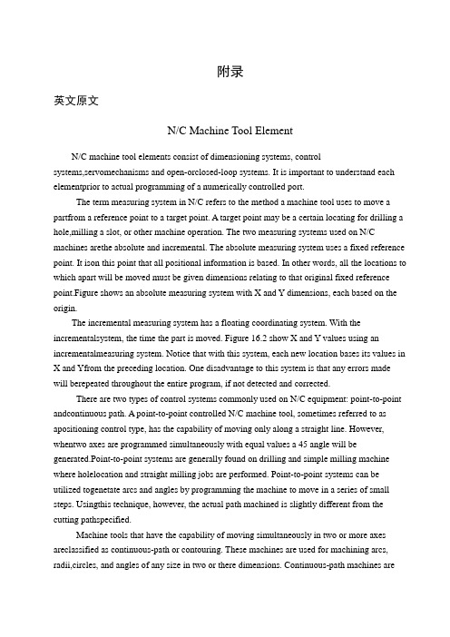
附录英文原文N/C Machine Tool ElementN/C machine tool elements consist of dimensioning systems, controlsystems,servomechanisms and open-orclosed-loop systems. It is important to understand each elementprior to actual programming of a numerically controlled port.The term measuring system in N/C refers to the method a machine tool uses to move a partfrom a reference point to a target point. A target point may be a certain locating for drilling a hole,milling a slot, or other machine operation. The two measuring systems used on N/C machines arethe absolute and incremental. The absolute measuring system uses a fixed reference point. It ison this point that all positional information is based. In other words, all the locations to which apart will be moved must be given dimensions relating to that original fixed reference point.Figure shows an absolute measuring system with X and Y dimensions, each based on the origin.The incremental measuring system has a floating coordinating system. With the incrementalsystem, the time the part is moved. Figure 16.2 show X and Y values using an incrementalmeasuring system. Notice that with this system, each new location bases its values in X and Yfrom the preceding location. One disadvantage to this system is that any errors made will berepeated throughout the entire program, if not detected and corrected.There are two types of control systems commonly used on N/C equipment: point-to-point andcontinuous path. A point-to-point controlled N/C machine tool, sometimes referred to as apositioning control type, has the capability of moving only along a straight line. However, whentwo axes are programmed simultaneously with equal values a 45 angle will be generated.Point-to-point systems are generally found on drilling and simple milling machine where holelocation and straight milling jobs are performed. Point-to-point systems can be utilized togenetate arcs and angles by programming the machine to move in a series of small steps. Usingthis technique, however, the actual path machined is slightly different from the cutting pathspecified.Machine tools that have the capability of moving simultaneously in two or more axes areclassified as continuous-path or contouring. These machines are used for machining arcs, radii,circles, and angles of any size in two or there dimensions. Continuous-path machines aremoreexpensive than point-to-point systems and generally require a computer to aid programming when machining complex contours.N/C servomechanisms are devices used for producing accurate movement of a table or slid along an axis. Two types of servos are commonly used on N/C equipment: electric stepping motors and hydraulic motors. Stepping motor servos are frequently used on less expensive N/C equipment. These motors are generally high-torque power servos and mounted directly to a lead screw of a table or tool slide. Most stepping motors are actuated by magnetic pulses from the stator and rotor assemblies. The net result of this action is that one rotation of the motor shaft produces 200 steps. Connection the motor shaft to a 10-pitch lead screw allows 0.0005-in. movements to be made. Hydraulic servos produce a fluid pressure that flows through gears or pistons to effect shaft rotation. Mechanical motion of lead screws and slides is accomplished through various values and controls from these hydraulic motors. However, they are more expensive and noisy. Most larger N/C machines use hydraulic servos.N/C machines that use an open-loop system contain no-feedback signal to ensure that a machine axis has traveled the required distance. That is, if the input received was to move a particular table axis 1.000 in, the servo unit generally moves the table 1.000 in. There is no means for comparing the actual table movement with the input signal, howeve r, The only assurance that the table has actually moved 1.000 in. is the reliability of the servo system used.Open-loop systems are, of course, less expensive than closed-loop systems. A closed-loop system compares the actual output with the input signal and compensates for any errors. A feedback unit actually compares the amount the table has been moved with the input signal. Some feedback units used on closed-loop systems are transducers, electrical or magnetic scales, and synchros. Closed-loop systems greatly increase the reliability of N/C machines. Machining Centers Many of today’s more sophisticated lathes are called machining centers since they are capable of performing, in addition to the normal turning operations, certain milling and drilling operations. Basically, a machining center can be thought of as being a combination turret lathe and milling machine. Additional features are sometimes included by manufacturers to increase the versatility of their machines.Numerical ControlOne of the most fundamental concepts in the area of advanced manufacturing technologies is numerical control (NC). Prior to the advent of NC, all machine tools were manually operated and controlled .Among the many limitations associated with manual control machine tools, perhaps none is more prominent than the limitation of operator skills. With manual control, the quality of the product is directly related to and limited to the skills of the operator. Numerical control represents the first major step away from human control of machine tools.Numerical control means the control of machine tools and other manufacturing systems through the use of prerecorded, written symbolic instructions. Rather than operating a machine tool, an NC technician writes a program that issues operational instructions to the machine tool. For a machine tool to be numerically controlled, it must be interfaced with a device for accepting and decoding the programmed instructions, known as a reader.Numerical control was developed to overcome the limitation of human operators, and it has done so. Numerical control machines are more accurate than manually operated machines, they can produce parts more uniformly, they are faster, and the long-run tooling costs are lower. The development of NC led to the development of several other innovations in manufacturing technology:1. Electrical discharge machining.2. Laser cutting.3. Electron beam welding.Numerical control has also made machine tools more versatile than their manually operated predecessors. An NC machine tool can automatically produce a wide variety of parts, each involving an assortment of widely varied and complex machining processes. Numerical control has allowed manufacturers to undertake the production of products that would not have been feasible from an economic perspective using manually controlled machine tools and processes. Like so many advanced technologies, NC was born in the laboratories of the Massachusetts Institute of Technology. The concept of NC was developed in the early 1950s with funding provided by the U. S. Air force. In its earliest stages, NC machines were able to make straight cuts efficiently and effectively.However, curved paths were a problem because the machine tool had to be programmed to undertake a series of horizontal and vertical steps to produce a curve. The shorter is the straight lines making up the steps, the smoother is the curve. Each line segment in the steps had to be calculated.This problem led to the development in 1959 of the Automatically Programmed Too ls (APT) language. This is a special programming language for NC that uses statements similar to English language to define the part geometry, describe the cutting tool configuration, and specify the necessary motions. The development of the APT language was a major step forward in the further development of NC technology. The original NC systems were vastly different from those used today. The machines had hardwired logic circuits. The instructional programs were written on punched paper, which was later to be replaced by magnetic plastic tape. A tape reader was used to interpret the instructions written on the tape for the machine. Together, all of this represented a giant step forward in the control of machine tools. However, there were a numberof problems with NC at this point in its development.A major problem was the fragility of the punched paper tape medium. It was common for the paper tape containing the programmed instructions to break or tear during a machining process. This problem was exacerbated by the fact that each successive time a part was produced on a machine tool, the paper tape carrying the programmed instructions had to be rerun through the reader. If it was necessary to produce 100 copies of a given part, it was also necessary to run the paper tape through the reader 100 separate times. Fragile paper tapes simply could not withstand the rigors of a shop floor environment and this kind of repeated use.This led to the development of a special magnetic plastic tape. Whereas the paper tape carried the programmed instructions as a series of holes punched in the tape, the plastic tape carried the instructions as a series of holes punched in the tape, the plastic tape carried the instructions as a series of magnetic dots. The plastic tape was much stronger than the paper taps, which solved the problem of frequent tearing and breakage. However, it still left two other problems.The most important of these was that it was difficult or impossible to change the instructions entered on the tape. To make even the most minor adjustments in a program of instructions, it was necessary to interrupt machining operations and make a new tape .It was also still necessary to run the tape through the reader as many times as there were parts to be produced. Fortunately, computer technology became a reality and soon solved the problems of NC associated with punched paper and plastic tape.The development of a concept known as direct numerical control (DNC) solved the paper and plastic tape problems associated with numerical control by simply eliminating tape as the medium for carrying the programmed instructions. In direct numerical control .machine tools are tied, via a data transmission link, to a host computer. Programs for operating the machine tools are stored in the host computer and fed to the machine tool as needed via the data transmission linkage. Direct numerical control represented a major step forward over punched tape and plastic tape. However, it is subject to the same limitations as all technologies that depend on a host computer. When the lost computer goes down, the machine tools also experience downtime. This problem led to the development of computer numerical control.The development of the microprocessor allowed for the development of programmable logic controllers (PLCs) and microcomputers. These two technologies allowed for the development of computer numerical control (CNC).With CNC, each machine tool has a PLC or a microcomputer that serves the same purpose. This allows programs to be input and stored at each individual machine tool. It also allows programs to be developed off-line and downloaded at the individual machine tool. CNC solved the problems associated with downtime of the hostcomputer, but it introduced another known as data management. The same program might be loaded on ten different microcomputers with no communication among them. This problem is in the process of being solved by local area networks that connect microcomputers for better data management. Cutting Tool GeometryShape of cutting tools, particularly the angles, and tool material are very important factors. Angles determine greatly not only tool life but finish quality as well. General principles upon which cutting tool angles are based do not depend on the particular tool, Basically, the same considerations hold true whether a lathe tool, a milling cutter, a drill, or even a grinding wheel are being designed. Since, however the lathe tool, depicted in Fig. 18.1, might be easiest to visualize, its geometry is discussed.Tool features have been identified by many names. The technical literature is full of confusing terminology. Thus in the attempt to cleat up existing disorganized conceptions and nomenclature, this American Society of Mechanical Engineers published AS A Standard B5-22-1950. What follows is based on it.A single-point tool is a cutting tool having one face and one continuous cutting edge, Tool angles identified in Fig. 18.2 are as follows:Tool angle 1, on front view, is the back-rank angle. It is the angle between the tool face and a line parallel to the tool base of the shank in a longitudinal plane perpendicular to the tool base. When this angle is downward from front to rear of the cutting edge, the rake is positive; when upward from front to black, the rake is negative. This angle is most significant in the machining process, because it directly affects the cutting force, finish, and tool life.The side-rake angle, numbered 2, measures the slope of the face on a cross plane perpendicular to the tool base. It, also, is an important angle, because it directs chip flow to the side of the tool post and permits the tool to feed more easily into the work.The end-relief angle is measured between a line perpendicular to the base and the end flank immediately below the end cutting edge; it is numbered 3 in the figure. It provides clearance between work and tool so that its cut surface can flow by with minimum rubbing against the tool. To save time, a portion of the end flank of the tool may sometimes be lest unground, having been previously forged to size. In such case, this end-clearance angle, numbered 4, measured to the end flank surface below the ground portion, would be larger than the relief angle.Often the end cutting edge is oblique to the flank. The relief angle is then best measured in a plane normal to the end cutting edge angle. Relief is also expressed as viewed from side and end of the tool.The side-relief angle, indicated as 5, is measured between the side flank, just below thecutting edge, and a line through the cutting edge perpendicular to the base of the tool. This clearance permits the tool to advance more smoothly into the work.Angle 6 is the end-cutting-edge angle measured between the end cutting edge and a line perpendicular to the side of the tool shank. This angle prevents rubbing of the cut surface and permits longer tool file.The side-cutting-edge angle, numbered 7, is the angle between the side cutting edge and the side of the tool shank. The true length of cut is along this edge. Thus the angel determines the distribution of the cutting forces. The greater the angle, the longer the tool life; but the possibility of charter increases. A compromise must, as usual, be reached.The nose angle, number 8, is the angle between the two component cutting edges. If the corner is rounded off, the arc size is defined by the nose radius 9. The radius size influences finish and chatter.Sand CastingThe first stage in the production of sand castings must be the design and manufacture of a suitable pattern. Casting patterns are generally made from hard word and the pattern has to be made larger than the finished casting size to allow for the shrinkage that takes place during solidification and cooling. The extent of this shrinkage varies with the type of metal or alloy to be cast. For all but the simplest shapes the pattern will be made in two or more pieces to facilitate moulding. If a hollow casting is to be made the pattern design will include extension pieces so that spaces to accept the sand core are moulded into sand. These additional spaces in the mould are termed core prints.Sand moulds for the production of small and medium-sized castings are made in a moulding box. The mould is made in two or more parts in order that the pattern may be removed.The drag half of the mould box is placed on a flat firm board and the drag half of the pattern placed in position. Facing sand is sprinkled over the pattern and then the mould box is filled with moulding sand. The sand is rammed firmly around the pattern. This process of filling and ramming may be done by hand but mould production is automated in a large foundry with the mould boxes moving along a conveyor, firstly to be filled with sand from hoppers and then to pass under mechanical hammers for ramming. When ramming of the sand is complete, excess sand is removed to leave a smooth surface flush with the edges of the moulding box.The completed drag is now turned over and the upper, or cope, portion of the moulding box positioned over it. The cope half of the pattern is placed in position, correct alignment being ensured by means of small dowel pins. Patterns for the necessary feeder, runner and risers are also placed so as to give an even distribution of metal into the mould cavity. The rise rs should coincide with the highest readily escape from the mould. The sizes of risers should be such thatthe metal in them does not freeze too rapidly. An important function of a riser is to act as reservoir of liquid metal to feed solidification within the mould. A thin coating of dry parting sand is sprinkled into mould at this stage. This is to prevent the cope and drag sticking together when the cope half is moulded. The cope is now filled with moulding sand and this is rammed firmly into shape in the same manner as in the making of the drag.After the ramming of sand in the cope is completed the two halves of the moulding box are carefully separated. At this stage venting of the moulding box are carefully separated. At this stage venting of the mould can be done, if necessary, to increase the permeability of the mould. After venting the patterns are carefully removed from both cope and drag, and a gate or gates are carefully cut to connect the runner channel with the main cavity. Gates should be sited to allow or entry into mould with a minimum of turbulence. Any loose sand is gently blown away and if a core is to be used it the cope upon the drag and it is then ready for use. Liquid metal is poured smoothly into the mould via the feeder. Pouring ceases when liquid metal appears at the top of the risers and the feeder channel is also full.When the metal that has been poured into a sand mould has fully solidified the mould is broken and casting is removed. The casting still has the runner and risers attached to it and there will be sand adhering to portions of the surface. Runners and risers are cut off and returned to the melting furnace. Sand cores are broken and adherent sand is cleaned from the surface by vibration or by sand blasting with dry sand. Any fins or metal flash formed at mould parting lines are removed by grinding and the castings are then ready for inspection.The main Elements of Horizontal Milling MachinesColumn and base The column and base form the foundation of the complete machine. Both are made from cast iron, designed with thick sections to ensure complete rigidity and freedom form vibration. The base, upon which the column is mounted, is also the cutting-fluid reservoir and contains the pump to circulate the fluid to cutting area.The column contains the spindle, accurately located in precision bearings. The spindle id driven through a gearbox from a vee-belt drive from the electric motor housed at the base of column. The gearbox enables a range of spindle speeds to be selected. In the model shown, twelve spindle speeds from 32 to 1400rev/min are available. The front of column carries the guideways upon which the knee is located and guided in a vertical direction.KneeThe knee, mounted on the column guideways, provides the vertical movement of the table. Power feed is available, through a gearbox mounted on the side, from a separate built-in motor, providing a range of twelve feed rates from 6 to 250mm/min. Drive is through a leadscrew, whose bottom end is fixed to machine base. Provision is made to raise and lower the knee byhand through a leadscrew and nut operates by a handwheel at the front. The knee has guideways on its top surface giving full-width support to the saddle and guiding it in a transverse direction. lock is provided to clamp the knee in any vertical position on the column.SaddleThe saddle, mounted on the knee guideways, providers the transverse movement of the table. Power feed is provided through the gearbox on the knee. A range of twelve feeds is available, from 12 to 500mm/min. Alternative hand movement is provided through a leadscrew and nut by a hand heel at the front of the knee.Camping of saddle to the knee is achieved by two clamps on the side of the saddle.The saddle has dovetail gun its upper surface, at right angles to the knee guideways, to provide a guide to the table in a longitudinal direction.TableThe table provides the surface upon which all workpieces and workholding equipment are located and clamped. A series of tee slots is provided for this purpose. The dovetail guides on undersurface locate in the guideways on the saddle, giving straight-line movement to the table in longitudinal direction at right angles to the saddle movement.Power feed is provided from the knee gearbox, through the saddle, to the table leadscrew. Alternative hand feed is provided by a handwheel at each end of the table. Stops at the front of the table can be set to disengage the longitudinal feed automatically in each direction. Spindle The spindle, accurately mounted in precision bearings, provides the drive for the milling cutters. Cutters can be mounted straight on the spindle nose or in curter-holding devices which in turn are mounted in the spindle, held in position by a drawbolt passing the hold spindle. Spindles of milling machines have a standard spindle nose to allow for easy interchange of cutters and cutter-holding devices. The bore of the nose is tapered to provide accurate location, the angle of taper being 1. The diameter of the taper depends on the size of the machine and may be 30,40,or 50 IST. Due to their steepness of angle, there tapers –known as non-stick or self-releasing- cannot be relied upon to transmit the drive to the cutter or cutter-holding device. Two driving keys are provided to transmit the drive.Overarm and arbor supportDue to the length of arbors used, support is required at the outer end to prevent deflection when cutting takes place. Support is provided by an arbor-support bracket, clamped to an overarm which is mounted on top of the column in a dovetail slide. The overarm is adjustable in or out for different lengths of arbor, or can be fully pushed in when arbor support is not required. Two clamping bolts are support is located in the overarm dovetail and is locked by which the arbor runs during splindle rotation.中文译文数控机床的组成部分数控机床的组成部分包括测量系统、控制系统、伺服系统及开环或闭环系统,在对数控零件进行实际程序设计之前,了解各组成部分是重要的。
《机械外文翻译文献翻译液压传动》
英文原文Hydraulic SystemHydraulic presser drive and air pressure drive hydraulic fluid as the transmission is made according to the 17th century, Pascal's principle of hydrostatic pressure to drive the development of an emerging technology, the United Kingdo m in 1795 • Braman Joseph (Joseph Braman ,1749-1814), in London water as a medium to form hydraulic press used in industry, the birth of the world's first hydraulic press. Media work in 1905 will be replaced by oil-water and further improved.Hydraulic transmission There are many outstanding advantages, it is widely used, such as general industr- ial use of plastics processing machinery, the pressure of machinery, machine tools, etc.; operating machinery engineering machinery, construction machinery, agricultural machinery, automobiles, etc.; iron and steel indu- stry metallurgical machinery, lifting equipment, such as roller adjustment device; civil water projects with flo- od control and dam gate devices, bed lifts installations, bridges and other manipulation of institutions; speed turbine power plant installations, nuclear power plants, etc.; ship from the deck heavy machinery (winch), the bow doors, bulkhead valve, stern thruster, etc.; special antenna technology giant with control devices, measu- rement buoys, movements such as rotating stage; military-industrial control devices used in artillery, ship anti- rolling devices, aircraft simulation, aircraft retractable landing gear and rudder control devices and other devi- ces.A complete hydraulic system consists of five parts, namely, power components, the implementation of co- mponents, control components, auxiliary components and hydraulic oil.The role of dynamic components of the original motive fluid into mechanical energy to the pressure that the hydraulic system of pumps, it is to power the entire hydraulic system. The structure of the form of hydra- ulic pump gears are generally pump, vane pump and piston pump.Implementation of components (such as hydraulic cylinders and hydraulic motors) which is the pressure of the liquid can be converted to mechanical energy to drive the load for a straight line reciprocating movement or rotational movement.Control components (that is, the various hydraulic valves) in the hydraulic system to control and regulate the pressure of liquid, flow rate and direction. According to the different control functions, hydraulic pressure control valve can be divided into valves, flow control valves and directional control valve. Pressure control valves are divided into benefits flow valve (safety valve), pressure relief valve, sequence valve, pressure relays, etc.; flow control valves including throttle, adjusting the valves, flow diversion valve sets, etc.; directional control valve includes a one-way valve , one-way fluid control valve, shuttle valve, valve and so on. Under the control of different ways, can be divided into the hydraulic valve control switch valve, control valve and set the value of the ratio control valve.Auxiliary components, including fuel tanks, oil filters, tubing and pipe joints, seals, pressure gauge, oil level, such as oil dollars.Hydraulic oil in the hydraulic system is the work of the energy transfer medium, there are a variety of mineral oil, emulsion oil hydraulic molding Hop categories.The role of the hydraulic system is to help humanity work. Mainly by the implementation of components to rotate or pressure into a reciprocating motion.Hydraulic system and hydraulic power control signal is composed of two parts, the signal control of some parts of the hydraulic power used to drive the control valve movement.Part of the hydraulic power means that the circuit diagram used to show the different functions of the interrelationship between components. Containing the source of hydraulic pump, hydraulic motor and auxiliary components; hydraulic control part contains a variety of control valves, used to control the flow of oil, pressure and direction; operative or hydraulic cylinder with hydraulic motors, according to the actual requirements of their choice.In the analysis and design of the actual task, the general block diagram shows the actual operation of equi - pment. Hollow arrow indicates the signal flow, while the solid arrows that energy flow.Basic hydraulic circuit of the action sequence - Control components (two four-way valve) and the spring to reset for the implementation of components (double-acting hydraulic cylinder), as well as the extending and retracting the relief valve opened and closed . For the implementation of components and control components, presentations are based on the corresponding circuit diagram symbols, it also introduced ready made circuit diagram symbols.Working principle of the system, you can turn on all circuits to code. If the first implementation of components numbered 0, the control components associated with the identifier is 1. Out with the implementation of components corresponding to the identifier for the even components, then retracting and implementation of components corresponding to the identifier for the odd components. Hydraulic circuit carried out not only to deal with numbers, but also to deal with the actual device ID, in order to detect system failures.DIN ISO1219-2 standard definition of the number of component composition, which includes the following four parts: device ID, circuit ID, component ID and component ID. The entire system if only one device, device number may be omitted.Practice, another way is to code all of the hydraulic system components for numbers at this time, components and component code should be consistent with the list of numbers. This method is particularly applicable to complex hydraulic control system, each control loop are the corresponding number with the systemWith mechanical transmission, electrical transmission compared to the hydraulic drive has the following advantages:1, a variety of hydraulic components, can easily and flexibly to layout.2, light weight, small size, small inertia, fast response.3, to facilitate manipulation of control, enabling a wide range of stepless speed regulation (speed range of 2000:1).4, to achieve overload protection automatically.5, the general use of mineral oil as a working medium, the relative motion can be self-lubricating surface, long service life;6, it is easy to achieve linear motion /7, it is easy to achieve the automation of machines, when the joint control of the use of electro-hydraulic, not only can achieve a higher degree of process automation, and remote control can be achieved.The shortcomings of the hydraulic system:1, as a result of the resistance to fluid flow and leakage of the larger, so less efficient. If not handled properly, leakage is not only contaminated sites, but also may cause fire and explosion.2, vulnerable performance as a result of the impact of temperature change, it would be inappropriate in the high or low temperature conditions.3, the manufacture of precision hydraulic components require a higher, more expensive and hence the price. 4, due to the leakage of liquid medium and the compressibility and can not be strictly the transmission ratio. 5, hydraulic transmission is not easy to find out the reasons for failure; the use and maintenance requirements for a higher level of technology.In the hydraulic system and its system, the sealing device to prevent leakage of the work of media within and outside the dust and the intrusion of foreign bodies. Seals played the role of components, namely seals. Medium will result in leakage of waste, pollution and environmental machinery and even give rise to malfunctioning machinery and equipment for personal accident. Leakage within the hydraulic system will cause a sharp drop in volumetric efficiency, amounting to less than the required pressure, can not even work. Micro-invasive system of dust particles, can cause or exacerbate friction hydraulic component wear, and further lead to leakage.Therefore, seals and sealing device is an important hydraulic equipment components. The reliability of its机械专业中英文文献翻译work and life, is a measure of the hydraulic system an important indicator of good or bad. In addition to the closed space, are the use of seals, so that two adjacent coupling surface of the gap between the need to control the liquid can be sealed following the smallest gap. In the contact seal, pressed into self-seal-style and self-styled self-tight seal (ie, sealed lips) two.The three hydraulic system diseases1, as a result of heat transmission medium (hydraulic oil) in the flow velocity in various parts of the existence of different, resulting in the existence of a liquid within the internal friction of liquids and pipelines at the sam- e time there is friction between the inner wall, which are a result of hydraulic the reasons for the oil tempera- ture. Temperature will lead to increased internal and external leakage, reducing its mechanical efficiency. At the same time as a result of high temperature, hydraulic oil expansion will occur, resulting in increased com- pression, so that action can not be very good control of transmission. Solution: heat is the inherent characte -ristics of the hydraulic system, not only to minimize eradication. Use a good quality hydraulic oil, hydraulic piping arrangement should be avoided as far as possible the emergence of bend, the use of high-quality pipe and fittings, hydraulic valves, etc.2, the vibration of the vibration of the hydraulic system is also one of its malaise. As a result of hydraulic oil in the pipeline flow of high-speed impact and the control valve to open the closure of the impact of the process are the reasons for the vibration system. Strong vibration control action will cause the system to error, the system will also be some of the more sophisticated equipment error, resulting in system failures. Solutions: hydraulic pipe should be fixed to avoid sharp bends. To avoid frequent changes in flow direction, can not avoid damping measures should be doing a good job. The entire hydraulic system should have a good damping measures, while avoiding the external local oscillator on the system.3, the leakage of the hydraulic system leak into inside and outside the leakage leakage. Leakage refers to the process with the leak occurred in the system, such as hydraulic piston-cylinder on both sides of the leakage, the control valve spool and valve body, such as between the leakage. Although no internal leakage of hydra- ulic fluid loss, but due to leakage, the control of the established movements may be affected until the cause system failures. Outside means the occurrence of leakage in the system and the leakage between the external environment. Direct leakage of hydraulic oil into the environment, in addition to the system will affect the working environment, not enough pressure will cause the system to trigger a fault. Leakage into the enviro- nment of the hydraulic oil was also the danger of fire. Solution: the use of better quality seals to improve the machining accuracy of equipment.Another: the hydraulic system for the three diseases, it was summed up: "fever, with a father拉稀" (This is the summary of the northeast people). Hydraulic system for the lifts, excavators, pumping station, dynamic, crane, and so on large-scale industry, construction, factories, enterprises, as well as elevators, lifting platforms, Deng Axle industry and so on.Hydraulic components will be high-performance, high-quality, high reliability, the system sets the direction of development; to the low power, low noise, vibration, without leakage, as well as pollution control, water-based media applications to adapt to environmental requirements, such as the direction of development; the development of highly integrated high power density, intelligence, mechatronics and micro-light mini-hydraulic components; active use of new techniques, new materials and electronics, sensing and other high-tech.Hydraulic coupling to high-speed high-power and integrated development of hydraulic transmission equ- ipment, development of water hydraulic coupling medium speed and the field of automotive applications to develop hydraulic reducer, improve product reliability and working hours MTBF; hydraulic torque converter to the development of high-power products, parts and components to improve the manufacturing process tech -nology to improve reliability, promote computer-aided technology, the development of hydraulic torque con- verter and power shift transmission technology supporting the use of ; Clutch fluid viscosity should increase the quality of products, the formation of bulk to the high-power and high-speed direction.Pneumatic Industry:Products to small size, light weight, low power consumption, integrated portfolio of development, the implementation of the various types of components, compact structure, high positioning accuracy of the direction of development; pneumatic components and electronic technology, to the intelligent direction of development; component performance to high-speed, high-frequency, high-response, high-life, high temp- erature, high voltage direction, commonly used oil-free lubrication, application of new technology, new technology and new materials.(1)used high-pressure hydraulic components and the pressure of continuous work to reach 40Mpa, the maximum pressure to achieve instant 48Mpa;(2) diversification of regulation and control;(3) to further improve the regulation performance, increase the efficiency of the powertrain;(4) development and mechanical, hydraulic, power transmission of the composite portfolio adjustment gear;(5) development of energy saving, energy efficient system function;(6) to further reduce the noise;(7) Application of Hydraulic Cartridge V alves thread technology, compact structure, to reduce the oil spill Water-based hydraulic systemsWater-based hydraulic systems traditionally have been used in hot-metal areas of steel mills. The obvious advantage of water systems in these industries is their fire resistance. Water-based hydraulic systems also have obvious cost advantages over oil-based fluid. First, non-toxic, biodegradable synthetic additives for water cost $5 to $6 per gallon. One gallon of concentrate can make 20 gallons of a 5% solution, so the cost of water-based hydraulic fluid actually can be less than 30 cents per gallon.Considering the costs associated with preventing and cleaning up environmental contamination, water-based hydraulic systems hold the potential for tremendous cost savings at the plant level. Oil that has leaked already becomes a very important problem. It must be collected, properly contained. Water containing synthetic additives, however, can by dumped into plant effluent systems.Cost savings at the plant level don't stop at the lower cost of the fluid and its disposal. Because water-based hydraulic fluid consists of 10 parts water and one part synthetic additive, 5 gallons of additive mixes with water to make 100 gallons of water-based fluid. A 50gallon container is certainly easier to handle than two 55-gallon drums, so warehousing is simpler, cleaner, and less cluttered. Transportation costs also are lower.Other potential plant-wide savings include improved safety for workers because the water-based fluid is non-toxic as well as non-flammable. These attributes can reduce plant insurance rates. Spills cost less to clean up because granular absorbents or absorbent socks are unnecessary. Water is "hot" againThe oil embargo in the 1970s sparked interest in water-based fluids as a less-costly alternative to oils. Even the most expensive water additives became attractive when designers learned that one gallon of concentrate would make 20 gallons of fluid.As oil prices gradually dropped, so did interest in water-based hydraulics. In retrospect, interest in water-based fluids centered around their cost saving potential. Most designers lost interest when they discovered that they could not just change the fluid in their systems from oil to water without making other substantial changes. They then become reluctant to accept other "disadvantages" - read substantial changes - of switching over to water-based hydraulics.What were viewed as disadvantages were really different rules that apply to water-based hydraulic systems? Designers probably resisted learning more about water-based hydraulics because they were intimated by all the work required to lean about how to design a new system or retrofit an older system. By closing their minds to this different technology, they missed the many other advantages of water-based fluid beyond initial cost. Now that environmental concerns have added disposal costs to the price of hydraulic fluids, water-based hydraulics has again become a hot topic.Fighting freezeWater-based hydraulic systems do, of course, have limits to their applications. One limitation is the potential of freezing. This possibility is probably the most significant blockade to more widespread application of机械专业中英文文献翻译water-based systems, especially in the mobile equipment industry. Longwall mining is by far the largest sector of mobile equipment that has been able to take advantage of water-based systems. Temperatures underground do not approach the freezing point of water, and fire resistance is essential. Mobile and even marine equipment used in temperate climates could cash in one the advantages of water based systems, but there is no guarantee that such equipment always will be used in above-freezing temperatures.Nevertheless, adding an anti-freeze to a water-based fluid can depress its freezing temperature to well below 32°F. Ethylene glycol - used in automotive anti-freeze - is toxic and is not biodegradable, so its use for anti-freeze in water-based hydraulic fluid would defeat the environmental advantage water-based fluid has. There is an alternative. Propylene glycol is not toxic and is biodegradable. It costs more than ethylene glycol and is not quite as effective antifreeze, so it must be used in slightly higher concentrations. Two more techniques to reduce freezing potential are to keep fluid circulating continuously and use hose where practical. Sealing the systemTwo more perceived problems with water hydraulic systems are bacterial infestation and difficulty in maintain proper concentrations. Sealing the system from atmosphere can hold bacterial growth in check. Addition of an anti-bacterial agent to the fluid can have a lasting effect on preventing bacterial buildup if air is excluded from the system.A sealed reservoir eliminates another problem suffered by many hydraulic systems: water ingression. This addresses another misconception about water-based systems: water-based systems not sealed from the atmosphere must be closely monitored to ensure that the additive concentration stays within tolerance. That is because water evaporates from the reservoir more readily than the additive does. Consequently, water evaporation causes the additive concentration to increase. When new fluid is added to a system, samples of the existing fluid must be taken to determine the concentration of additive in solution. These results then reveal the ratio of additive to fluid that must be added so that fluid concentration is correct.With a system that seals fluid from the atmosphere, the evaporation problem is virtually eliminated. Fluid that escapes by leakage is a solution containing water and additive. Therefore, the quantity of fluid in the system changes, but concentration does not. System fluid is replen ished simply by adding a pre-mixed solution of water and additive to the reservoir.中文原文液压传动液压传动和气压传动称为流体传动,是根据17世纪帕斯卡提出的液体静压力传动原理而发展起来的一门新兴技术,1795年英国约瑟夫•布拉曼(Joseph Braman,1749-1814),在伦敦用水作为工作介质,以水压机的形式将其应用于工业上,诞生了世界上第一台水压机。
机械加工——机械类外文翻译、中英文翻译

TOOL WEAR MECHANISMS ON THE FLANK SURFACE OF CUTTINGINSERTSFOR HIGH SPEED WET MACHINING5.1 IntroductionAlmost every type of machining such as turning, milling, drilling, grinding..., uses a cutting fluid to assist in the cost effective production of pa rts as set up standard required by the producer [1]. Using coolant with some cutting tools material causes severe failure due to the lack of their resistance to thermal shock (like AL2O3 ceramics), used to turn steel. Other cutting tools materials like cubic boron nitride (CBN) can be used without coolant, due to the type of their function. The aim of using CBN is to raise the temperature of the workpice to high so it locally softens and can be easily machined.The reasons behind using cutting fluids can be summarized as follows.® Extending the cutting tool life achieved by reducing heat generated and as a result less wear rate is achieved. It will also eliminate the heat from theshear zone and the formed chips.® Cooling the work piece of high quality materia l under operation plays an important role since thermal distortion of the surface and subsurfacedamage is a result of excessive heat that must be eliminated or largelyreduced to produce a high quality product.Reducing cutting forces by its lubricating e ffect at the contact interface region and washing and cleaning the cutting region during machining from small chips. The two main reasons for using cutting fluids are cooling and lubrication.Cutting Fluid as a Coolant:The fluid characteristics and condition of use determine the coolant action of the cutting fluid, which improves the heat transfer at the shear zone between the cutting edge, work piece, and cutting fluid. The properties of the coolant in this case must include a high heat capacity to carry away heat and good thermal conductivity to absorb the heat from the cutting region. The water-based coolant emulsion with its excellent high heat capacity is able to reduce tool wear [44]. Cutting Fluid as a Lubricant:The purpose is to reduce friction bet ween the cutting edge, rake face and the work piece material or reducing the cutting forces (tangential component). As the friction drops the heat generated isdropped. As a result, the cutting tool wear rate is reduced and the surface finish is improved.Cutting Fluid PropertiesFree of perceivable odorPreserve clarity throughout lifeKind and unirritated to skin and eyes.Corrosion protection to the machine parts and work piece.Cost effective in terms off tool life, safety, dilution ratio, and fluid lif e.[1]5.1.1 Cutting Fluid TypesThere are two major categories of cutting fluidsNeat Cutting OilsNeat cutting oils are poor in their coolant characteristics but have an excellent lubricity. They are applied by flooding the work area by a pump and re-circulated through a filter, tank and nozzles. This type is not diluted by water, and may contain lubricity and extreme-pressure additives to enhance their cutting performance properties. The usage of this type has been declining for their poor cooling ability, causing fire risk, proven to cause health and safety risk to the operator [1].® Water Based or Water Soluble Cutting FluidsThis group is subdivided into three categories:1.Emulsion ` mineral soluble' white-milky color as a result of emulsion of oil inwater. Contain from 40%-80% mineral oil and an emulsifying agent beside corrosion inhibitors, beside biocide to inhibit the bacteria growth.2.Micro emulsion `semi-synthetic' invented in 1980's, has less oil concentrationand/or higher emulsifier ratio 10%-40% oil. Due to the high levels ofemulsifier the oil droplet size in the fluid are smaller which make the fluid more translucent and easy to see the work piece during operation. Otherimportant benefit is in its ability to emulsify any leakage of oil from themachine parts in the cutting fluid, a corrosion inhibitors, and bacteria control.3.Mineral oil free `synthetic' is a mix of chemicals, water, bacteria control,corrosion inhibitors, and dyes. Does not contain any mineral oils, andprovides good visibility.23 to the work piece. bare in mind that the lack of mineral oil in this type of cuttingfluid needs to take more attention to machine parts lubrication since it should not leave an oily film on the machine parts, and might cause seals degradation due the lack of protection.5.1.2 Cutting Fluid SelectionMany factors influence the selection of cutting fluid; mainly work piece material, type of machining operation, machine tool parts, paints, and seals. Table 5-1 prepared at the machine tool industry res earch association [2] provides suggestions on the type of fluid to be used.5.1.3 Coolant ManagementTo achieve a high level of cutting fluids performance and costeffectiveness, a coolant recycling system should be installed in the factory. This system will reduce the amount of new purchased coolant concentrate and coolant disposable, which will reduce manufacturing cost. It either done by the company itself or be rented out, depends on the budget and management policy of the company [1].Table 5-1 Guide to the selection of cutting fluids for general workshop applications.Machining operation Workpiece materialFree machining and low - carbon Medium- Carbon steels High Carbon and alloy steels Stainlessand heattreated GrindingClear type soluble oil, semi synthetic or chemical Turning General purpose, soluble oil, semi synthetic or synthetic fluid Extreme-pressuresoluble oil,semi-synthetic orsyntheticfluid Milling General purpose, soluble oil, semi synthetic or synthetic Extreme- pressure soluble oil, semi- synthetic or synthetic Extreme-pressuresoluble oil,semi-synthetic orsyntheticfluid(neat cutting oilsmay beDrillingExtreme- pressure soluble oil, semi- synthetic or GearShapping Extreme-pressure soluble oil, Neat-cutting oils preferable HobbingExtreme-pressure soluble oil, semi-synthetic or synthetic fluid (neat cutting oils may be Neat-cutti ng oils BratchingExtreme-pressure soluble oil, semi-synthetic or synthetic fluid (neat Tapping Extreme-pressure soluble oil, semi-synthetic or Neat-cuttingpreferableNote: some entreis deliberately extend over two or more columns, indicating awide range of possible applications. Other entries are confined to aspecific class of work material.Adopt ed f rom Edw ard and Wri ght [2]5.2 Wear Mechanisms Under Wet High Speed M achiningIt is a common belief that coolant usage in metal cutting reduces cuttingtemperature and extends tools life. However, this researchshowed that this is not necessarily true to be generalized overcutting inserts materials. Similar research was ca rried out ondifferent cutting inserts materials and cutting conditionssupporting our results. Gu et al [36] have recorded adifference in tool wear mechanisms between dry and wetcutting of C5 milling inserts. Tonshoff et al [44] alsoexhibited different wear mechanisms on AL 2O 3/TiC inserts inmachining ASTM 5115, when using coolants emulsionscompared to dry cutting. In addition, Avila and Abrao [20]experienced difference in wear mechanisms activated at theflank side, when using different coolants in t estingAL 2O 3lTiC tools in machining AISI4340 steel. The wearmechanisms and the behavior of the cutting inserts studied inthis research under wet high speed-machining (WHSM)condition is not fully understood. Therefore, it was theattempt of this research to focus on the contributions incoating development and coating techniques of newlydeveloped materials in order to upgrade their performance attough machining conditions. This valuable research providesinsight into production timesavings and increase inprofitability. Cost reductions are essential in the competitiveglobal economy; thus protecting local markets and consistingin the search of new ones.5.3 Experimental Observations on Wear Mechanisms of Un-CoatedCemented Carbide Cutting Inserts in High Speed WetMachiningIn this section, the observed wear mechanisms are presented of uncoated cemented carbide tool (KC313) in machining ASTM 4140 steel under wet condition. The overall performance of cemented carbide under using emulsion coolant has been improved in terms of extending tool life and reducing machining cost. Different types of wear mechanisms were activated at flank side of cutting inserts as a result of using coolant emulsion during machining processes. This was due to the effect of coolant in reducing the average temperature of the cutting tool edge and shear zone during machining. As a result abrasive wear was reduced leading longer tool life. The materials of cutting tools behave differently to coolant because of their varied resistance to thermal shock. The following observations recorded the behavior of cemented carbide during high speed machining under wet cutting.Figure5-1 shows the flank side of cutting inserts used at a cutting speed of 180m/min. The SEM images were recorded after 7 minutes of machining. It shows micro-abrasion wear, which identified by the narrow grooves along the flank side in the direction of metal flow, supported with similar observations documented by Barnes and Pashby [41] in testing through-coolant-drilling inserts of aluminum/SiC metal matrix composite. Since the cutting edge is the weakest part of the cutting insert geometry, edge fracture started first due to the early non-smooth engagement between the tool and the work piece material. Also, this is due to stress concentrations that might lead to a cohesive failure on the transient filleted flank cutting wedge region [51, 52]. The same image of micro-adhesion wear can be seen at the side and tool indicated by the half cone27 shape on the side of cutting tool. To investigate further, a zoom in view was taken atthe flank side with a magnification of 1000 times and presented in Figure 5-2A. It shows clear micro-abrasion wear aligned in the direction of metal flow, where the cobalt binder was worn first in a hi gher wear rate than WC grains which protruded as big spherical droplets. Figure 5-2B provides a zoom-in view that was taken at another location for the same flank side. Thermal pitting revealed by black spots in different depths and micro-cracks, propagated in multi directions as a result of using coolant. Therefore, theii~ial pitting, micro-adhesion and low levels of micro-abrasion activated under wet cutting; while high levels of micro-abrasion wear is activated under dry cutting (as presented in the prev ious Chapter).Figure 5-3A was taken for a cutting insert machined at 150mlmin. It shows a typical micro-adhesion wear, where quantities of chip metal were adhered at the flank side temporarily. Kopac [53] exhibited similar finding when testing HSS-TiN drill inserts in drilling SAE1045 steel. This adhered metal would later be plucked away taking grains of WC and binder from cutting inserts material and the process continues. In order to explore other types of wear that might exist, a zoom-in view with magnification of 750 times was taken as shown in Figure5-3B. Figure 5-3B show two forms of wears; firstly, micro-thermal cracks indicated by perpendicular cracks located at the right side of the picture, and supported with similar findings of Deamley and Trent [27]. Secondly, micro-abrasion wear at the left side of the image where the WC grains are to be plucked away after the cobalt binder was severely destroyed by micro-abrasion. Cobalt binders are small grains and WC is the big size grains. The severe distort ion of the binder along with the WC grains might be due to the activation of micro-adhesion and micro-abrasionFigure 5-1 SEM image of (KC313) showing micro abrasion and micro-adhesion (wet).SEM micrographs of (KC313) at 180m/min showing micro-abrasion where cobalt binder was worn first leaving protruded WC spherical droplets (wet).(a)SEM micrographs of (KC313) at 180m/min showing thermal pitting (wet).Figure 5-2 Magnified views of (KC313) under wet cutting: (a) SEM micrographs of (KC313) at 180mlmin showing micro-abrasion where cobalt binderwas worn first leaving protruded WC spherical droplets (wet ), (b) SEMmicrographs of (KC313) at 180.m/min showing thermal pitting (wet ).SEM image showing micro-adhesion wear mechanism under 150m/min (wet).(a)SEM image showing micro-thermal cracks, and micro-abrasion.Figure 5-3 Magnified views of (KC313) at 150m/min (wet): (a) SEM image showing micro-adhesion wear mechanism under 150m/min (wet), (b) SEM image showing micro-fatigue cracks, and micro-abrasion (wet).Wear at the time of cutting conditions of speed and coolant introduction. Therefore, micro-fatigue, micro-abrasion, and micro-adhesion wear mechanisms are activated under wet condition, while high levels of micro-abrasion were observed under dry one.Next, Figure 5-4A was taken at the next lower speed (120m/min). It shows build up edge (BUE) that has sustained its existence throughout the life of the cutting tool, similar to Huang [13], Gu et al [36] and Venkatsh et al [55]. This BUE has protected the tool edge and extended its life. Under dry cutting BUE has appeared at lower speeds (90 and 60 m/min), but when introducing coolant BUE started to develop at higher speeds, This is due to the drop in shear zone temperature that affected the chip metal fl ow over the cutting tool edge, by reducing the ductility to a level higher than the one existing at dry condition cutting. As a result, chip metal starts accumulating easier at the interface between metal chip flow, cutting tool edge and crater surface to form a BUE. In addition to BUE formation, micro-abrasion wear was activated at this speed indicated by narrow grooves.To explore the possibility of other wear mechanisms a zoom-in view with a magnification of 3500 times was taken and shown in Figure 5-4B. Micro- fatigue is evident by propagated cracks in the image similar to Deamley and Trent [27] finding. Furthermore, Figure 5-4B shows indications of micro-abrasion wear, revealed by the abrasion of cobalt binder and the remains of big protruded WC grains. However, the micro-abrasion appeared at this speed of 120m/min is less severe than the same type of micro-wear observed at 150m/min speed, supported with Barnes [41] similar findings. Therefore, micro-abrasion, BUE and micro-fatigue were activated under wet condition while, adhesion, high levels micro-abrasion, and no BUE were under dry cutting.SEM i m a g e o f(KC313) showing build up e d g e under 120m/min (wet).(a)SEM i m a g e o f(KC3 13) showing micro-fatigue, and micro-abrasion (wet). Figure 5-4 SEM images of (KC313) at 120m/min (wet), (a) SEM image of (KC313). showing build up edge, (b) SEM image of(K C313) showing micro-fatigue and micro-abrasion33 Figure 5-5 is for a cutting tool machined at 90m/min, that presents a goodcapture of one stage of tool life after the BUE has been plucked away. The bottom part of the flank side shows massive metal adhesion from the work piece material. The upper part of the figure at the edge shows edge fracture. To stand over the reason of edge fracture, the zoom-in view with magnification of 2000 times is presented in Figure 5-6A. The micro-fatigue crack image can be seen as well as micro-attrition revealed by numerous holes, and supported with Lim et al [31] observations on HSS-TiN inserts. As a result of BUE fracture from the cutting tool edge, small quantities from the cutting tool material is plucked away leaving behind numerous holes. Figure 5-6B is another zoom-in view of the upper part of flank side with a magnification of 1000 times and shows micro-abrasion wear indicated by the narrow grooves. Furthermore, the exact type of micro-wear mechanism appeared at the flank side under 60 m/min. Therefore, in comparison with dry cutting at the cutting speed of 90 m/min and 60 m/min, less micro-abrasion, bigger BUE formation, and higher micro-attrition rate were activated.Figure 5-5 SEM image showing tool edge after buildup edge was plucked away.SEM image showing micro-fatigue crack, and micro-attrition.(a)SEM image showing micro-abrasion.Figure 5-6 SEM images of (KC313) at 90m/min:(a) SEM image showing micro-fatigue crack, and micro-attrition, (b) SEM image showingmicro-abrasion.5.4 Experimental Observations on Wear Mechanisms of Coated CementedCarbide with TiN-TiCN-TiN Coating in High Speed WetMachiningInvestigating the wear mechanisms of sandwich coating under wet cutting is presented in this section starting from early stages of wear. Figure 5-7 shows early tool wear starting at the cutting edge when cutting at 410m/min. Edge fracture can be seen, it has started at cutting edge due to non-smooth contact between tool, work piece, micro-abrasion and stress concentrations. To investigate further the other possible reasons behind edge fracture that leads to coating spalling, a zoom-in view with magnification of 2000 ti mes was taken and presented at Figure 5-8A. Coating fracture can be seen where fragments of TiN (upper coating) had been plucked away by metal chips. This took place as result of micro-abrasion that led to coating spalling. On the other hand, the edge is t he weakest part of the cutting insert geometry and works as a stress concentrator might lead to a cohesive failure on the transient filleted flank cutting wedge region [51, 52].Both abrasion wear and stress concentration factor leave a non-uniform edge configuration at the micro scale after machining starts. Later small metal fragments started to adhere at the developed gaps to be later plucked away by the continuous chip movement as shown in Figure 5-8A. Another view of edge fracture was taken of the same cutting tool with a magnification of 2000 times as shown in Figure 5-8B. It presents fracture and crack at the honed tool edge. A schematic figure indicated by Figure 5-9, presented the progressive coated cutting inserts failure starting at the insert edge. It was also noticed during the inserts test that failure takes place first at the inserts edge then progressed toward the flank side. Consequently, a study on optimizing the cutting edgeFigure 5-7 SEM image of (KC732) at 410m/min showing edge fractur e and micro-abrasion (wet).SEM image showing edge fracture.(a)SEM image showing fracture and crack at the honed insert edge.Figure 5-8 SEM of (KC732) at 410m/min and early wear stage (wet): (a) SEM image showing edge fracture, (b) SEM image showing fr acture and crack atthe honed insert edge.radius to improve coating adhesion, and its wear resistance, might be also a topic for future work.Figure 5-1.0A was taken after tool failure at a speed of 410m/min. It shows completely exposed substrate and severe sliding wear at the flank side. The coating exists at the crater surface and faces less wear than the flank side. Therefore it works as an upper protector for the cutting edge and most of the wear will take place at the flank side as sliding wear. Figu re 5-10B is a zoom-in view with magnification of 3500 times, and shows coating remaining at the flank side. Nonetheless, micro-abrasion and a slight tensile fracture in the direction of metalchip flow. Ezugwa et al [28] and Kato [32] have exhibited simila r finding. However, the tensile fracture in this case is less in severity than what had been observed at dry cutting. This is due to the contribution of coolant in dropping the cutting temperature, which has reduced the plastic deformation at high temperature as a result. Hence, in comparison with the dry cutting at the same speed, tensile fracture was available with less severity and micro-abrasion/sliding. However, in dry cutting high levels of micro-abrasion, high levels of tensile fracture and sliding wear occurred.Figure 5-11 was taken at early stages of wear at a speed of 360m/min. It shows sliding wear, coating spalling and a crack starting to develop between TiN and TiCN coating at honed tool edge. Figure5-12A shows nice presentation of what had been described earlier regarding the development of small fragments on the tool edge. The adhered metal fragments work along with micro-abrasion wear to cause coating spalling.SEM image showing sliding wear.(a)SEM image showing micro-abrasion and tensile fracture.Figure 5-10 SEM images of (KC732) at 410m/min after failure (wet): (a) SEM image showing sliding wear, (b) SEM image showing micro-abrasionand tensile fracture.Figure 5-11 SEM image at early stage of wear of 360m/min (wet) showing coating and spalling developing crack between TiN and TiCN layers.The size of the metal chip adhered at the edge is almost 15g. Since it is unstable it will be later plucked away taking some fragments of coatings with it and the process continues. Another zoom in view with a magnification of 5000 times for the same insert is shown in Figure 5-12B indicating a newly developed crack between the coating layers.Figure 5-13A is taken of the same insert after failure when machining at 360m/min and wet condition. Coating spalling, and sliding wear can be seen and indicated by narrow grooves. In addition, initial development of notch wear can be seen at the maximum depth of cut.Further investigation is carried out by taking a zoom in view with a magnification of 2000 times as shown in Figure 5-13B. A clear micro-abrasion wear and micro-fatigue cracks were developed as shown, which extended deeply through out the entire three coating layers deep until the substrate. Therefore, in comparison with dry cutting, micro-fatigue crack, less tensile fracture, less micro-abrasion wear were activated at wet cutting. While micro- fatigue crack, high levels of micro-abrasion, and high levels of tensile fracture are distinguish the type of wear under dry condition at the same cutting spee d.Next, Figure 5-14A is taken for cutting tools machined at 310m/min. The results are similar to the previous inserts machined at 360m/min, where adhesion of metal fragments occurred at the tool edge, sliding wear and coating spalling. In addition, the black spot appeared at the top of the figure on the crater surface is a void resulting from imperfections in the coating process. At this condition, the crater surface will be worn faster than the flank surface.SEM image showing adhered metal fragments at tool edge.(a)SEM image showing developed crack between coating layers.Figure 5-12 SEM image of (KC732) at early wear 360m/min (wet): (a) SEM image showing adhered metal fragments at tool edge, (b) SEM image showingdeveloped crack between coating layers.(a)SEM image showing coating spalling and sliding wear after tool failure(b)SEM image showing micro-abrasion, and micro-fatigue cracks developedbetween coating layersFigure 5-13 SEM image of KC732 after failure machined at 360m/min(b)(wet): (a) SEM image showing coating spalling and sliding wear after toolfailure, (b) SEM image showing micro-abrasion, and micro-fatiguecracks developed between coating layers.翻译:在高速潮湿机械加工条件下后刀面表层磨损机理5.1 介绍几乎每类型用机器制造譬如转动, 碾碎, 钻井, 研..., 使用切口流体协助零件的有效的生产当设定标准由生产商[ 1 ] 需要。
- 1、下载文档前请自行甄别文档内容的完整性,平台不提供额外的编辑、内容补充、找答案等附加服务。
- 2、"仅部分预览"的文档,不可在线预览部分如存在完整性等问题,可反馈申请退款(可完整预览的文档不适用该条件!)。
- 3、如文档侵犯您的权益,请联系客服反馈,我们会尽快为您处理(人工客服工作时间:9:00-18:30)。
机械外文翻译中英文附录附录1英文原文Rolling Contact BearingsThe concern of a machine designer with ball and roller bearings is fivefold as follows:(a) life in relation to load; (b)stiffness,ie.deflections under load; (c) friction; (d) wear; (e) noise. For moderate loads and speeds the correct selection of a standard bearing on the basis of a load rating will become important where loads are high,although this is usually of less magnitude than that of the shafts or other components associated with the bearing. Where speeds are high special cooling arrangements become necessary which may increase fricitional drag. Wear is primarily associated with the introduction of contaminants,and sealing arrangements must be chosen with regard to the hostility of the environment.Because the high quality and low price of ball and roller bearing depends on quantity production,the task of the machine designer becomes one of selection rather than design. Rolling-contact bearings are generally made with steel which is through-hardened to about900HV,although in many mechanisms special races are not provided and the interacting surfaces are hardened to about 600HV. It is not surprising that,owing to the high stresses involved,a predominant form of failureshould be metal fatigue, and a good deal of work is based on accept values of life and it is general practice in bearing industry to define the load capacity of the bearing as that value below which 90 percent of a batch will exceed life of one million revolutions.Notwithstanding the fact that responsibility for basic design ofball and roller bearings rests with the bearing manufacturer, the machine designer must form a correct appreciation of the duty to be performed by the bearing and be concerned not only with bearingselection but with the conditions for correct installation.The fit of the bearing races onto the shaft or onto the housings is of critical importance because of their combined effect on the internal clearance of the bearing as well as preserving the desired degree of interference fit. Inadequate interference can induce serious trouble from fretting corrosion. The inner race is frequently located axially by against a shoulder. A radius at this point is essential for the avoidance of stress concentration and ball races are provided with a radius or chamfer to follow space for this.Where life is not the determining factor in design, it is usual to determine maximum loading by the amount to which a bearing will deflect under load. Thus the concept of "static load-carrying capacity" is understood to mean the load that can be applied to a bearing, which is either stationary or subject to slight swiveling motions, without impairing its running qualities for subsequent rotational motion. This has been determined by practical experience as the load which whenapplied to a bearing results in a total deformation of 0.0025mm for a ball 25mm in diameter.The successful functioning of many bearings depends upon providing them with adequate protection against their environment, and in some circumstances the environment must be protected from lubricants or products of deterioration of the bearing design. Moreover, seals which are applied to moving parts for any purpose are of interest to tribologists because they are components of bearing systems and can only be designed satisfactorily on basis of the appropriate bearing theory.Notwithstanding their importance, the amount of research effort that has been devoted to the understanding of the behavior of seals has been small when compared with that devoted to other aspects of bearing technology.LathesLathes are widely used in industry to produce all kinds of machined parts. Some are general purpose machines, and others are used to perform highly specialized operations.Engine lathesEngine lathes, of course, are general-purpose machine used in production and maintenance shop all over the the world. Sized ranger from small bench models to huge heavy duty pieces of equipment. Many of the larger lathes come equipped with attachments not commonly found in the ordinary shop, such as automatic shop for the carriage.Tracer or Duplicating LathesThe tracer or duplicating lathe is designed o produce irregularly shaped parts automatically. The basic operation of this lathe is as fallows. A template of either a flat or three-dimensional shape isplaced in a holder. A guide or pointer then moves along this shape andits movement controls that of the cutting tool. The duplication may include a square or tapered shoulder, grooves, tapers, and contours. Work such as motor shafts, spindles, pistons, rods, car axles, turbine shafts, and a variety of other objects can be turned using this type of lathe.Turret LathesWhen machining a complex workpiece on a general-purpose lathe, agreat deal of time is spent changing and adjusting the several toolsthat are needed to complete the work. One of the first adaptations ofthe engine lathe which made it suitable to mass production was the addition of multi-tool in place of the tailstock. Although most turrets have six stations, some have as many as eight.High-production turret lathes are very complicated machines with a wide variety of power accessories. The principal feature of all turret lathes, however, is that the tools can perform a consecutive serials of operations in proper sequence. Once the tools have been set and adjusted, little skill is require to run out duplicate parts.Automatic Screw MachineScrew machines are similar in construction to turret lathes, except that their heads are designed to hold and feed long bars of stock.Otherwise, their is little different between them. Both are designed for multiple tooling, and both have adaptations for identical work. Originally, the turret lathe was designed as a chucking lathe for machining small casting, forgings, and irregularly shaped workpieces.The first screw machines were designed to feed bar stock and wire used in making small screw parts. Today, however, the turret lathe is frequently used with a collect attachment, and the automatic screw machine can be equipped with a chuck to hold castings.The single-spindle automatic screw machine, as its name implies, machines work on only one bar of stock at a time. A bar 16 to 20 feet long is feed through the headstock spindle and is held firmly by a collect. The machining operations are done by cutting tools mounted on the cross slide. When the machine is in operation, the spindle and the stock are rotated at selected speeds for different operations. If required, rapid reversal of spindle direction is also possible.In the single-spindle automatic screw machine, a specific length of stock is automatically fed through the spindle to a machining area. At this point, the turret and cross slide move into position and automatically perform whatever operations are required. After the machined piece is cut off, stock is again fed into the machining area and the entire cycle is repeated.Multiple-spindle automatic screw machines have from four to eight spindles located around a spindle carrier. Long bars of stock, supported at the rear of the machine,pass though these hollow spindles and aregripped by collects. With the single spindle machines, the turret indexes around the spindle. When one tool on the turret is working, the others are not. With a multiple spindle machine, however, the spindle itself index. Thus the bars of stock are carried to thevarious end working and side working tools. Each tool operates in only one position, but tolls operate simultaneously. Therefore, four to eight workpieces can be machined at the same time.Vertical Turret LathesA vertical turret is basically a turret lathe that has been stood on its headstock end. It is designed to perform a variety of turning operations. It consists of a turret, a revolving table, and a side head with a square turret for holding additional tools. Operations performed by any of the tools mounted on the turret or side head can be controlled through the use of stops.Machining CentersMany of today's more sophisticated lathes are called machining centers since they are capable of performing, in addition to the normal turning operations, certain milling and drilling operations. Basically, a machining center can be thought of as being a combination turret lathe and milling machine. Additional features are sometimes included by the versatility of their machines.Numerical ControlOne of the most fundamental concepts in the area of advanced manufacturing technologies is numerical control(NC). Prior to the adventof NC, all machine tools were manually operated and controlled. Among the many limitations associated with manual control machine tools, perhaps none is more prominent than limitation of operator skills. With manual control, the quality of the product is directly related to and limited to the skills of the operator. Numerical control represents the first major step away from human control of machine tools.Numerical control means the control of machine tools and other manufacturing systems through the use of prerecorded, written symbolic instructions. Rather than operating a machine tool, an NC technician tool to be numerically controlled, it must be interfaced with a device for accepting and decoding the programmed instructions, known as a reader.Numerical control was developed to overcome the limitation of human operators, and it has done so. Numerical control machines are more accurate than manually operated machines, they can produce parts more uniformly, they are faster, and the long-run tooling costs are lower. The development of NC led to the development of several other innovations in manufacturing technology:1. Electrical discharge machining.2. Laser cutting.3. Electron beam welding.Numerical control has also made machines tools more versatile than their manually operated predecessors. An NC machine tool can automatically produce a wide variety of parts, each involving anassortment of widely varied and complex machining processes. Numerical control has allowed manufacturers to undertake the production of products that would not have been feasible from an economic perspective using manually controlled machine tools and processes.Like so many advanced technologies, NC was born in the laboratories of the Masschusetts Institute of Technology. The concept of NC was developed in early 1950s with funding provided by the U.S.Air force. In its earliest stages, NC machines were able to make straight cuts efficiently and effectively.However,curved paths were a problem because the machine tool had to be programmed to undertake a series of horizontal and vertical steps to produce a curve. The shorter is straight lines making up the steps, the smoother is the curve. Each line segment in the steps had to be calculated.This problem led to the development in 1959 of the Automatically Programmed Tools(APT) language. This is a special programming language for NC that uses statements similar to English language to define the part geometry, describe the cutting tool configuration, and specify the necessary motions. The development of the APT language was a major step forward in the further development of NC technology. The original NC systems were vastly different from those used today. The machines had hardwired logic circuits. This instructional programs were written on punched paper, which was later to be replaced by magnetic plastic tape.A tape reader was used to interpret the instructions written on the tapefor the machine. Together, all of this represented a giant step forwardin the control of machine tools. However, there were a number ofproblems with NC at this point in its development.A major problem wad the fragility of the punched paper tape medium.It was common for the paper tape containing the programmed instructionsto break or tear during a machining process. This problem wasexacerbated by the fact that each programmed instructions had to bereturn through the reader. If it was necessary to produce 100 copies ofa given part,it was also necessary to run the paper tape through the reader 100 separate times. Fragile paper tapes simply could notwithstand the rigors of a shop floor environment and this kind ofrepeated use.This led to the development of a special magnetic plastic tape. Whereas the paper tape carried the programmed instructions as a seriesof holes punched in the tape, the plastic tapecarried the instructions as a series of magnetic dots. The plastictape was much stronger than the paper taps, which solved the problem of frequent tearing and breakage. However, it still left two other problems.The most important of these was that it was difficult or impossibleto change the instructions entered on the tape. To make even the most minor adjustments in a program of instructions, it necessary tointerrupt machining operations and make a new tape. It was also still necessary to run the tape through the reader as many times as there were parts to be produced. Fortunately, computer technology became a realityand soon solved the problem of NC associated with punched paper and plastic tape.The development of a concept known as direct numericalcontrol(DNC)solved the paper and plastic tape problems associated with numerical control by simply eliminating tape as the medium for carrying the programmed instructions. In direct numerical control machine tools are tied, via a data transmission link, to a host computer. Programs for operating the machine tools are stored in the host computer and fed to the machine tool as needed via the data transmission linkage. Direct numerical control represented a major step forward over punched tape and plastic tape. However, it is subject to the same limitations as all technologies that depend o a host computer. When the lost computer goes down, the machine tools also experience downtime. This problem led to the development of computer numerical control.The development of the microprocessor allowed for the development of programmable logic controllers(PNC)and microcomputer. These two technologies allowed for the development of computer numericalcontrol(CNC). With CNC, each machine tool has a PLC or a microcomputer that serves the same purpose. This allows programs to be input and stored at each individual machine tool. It also allows programs to be developed off-line and download at the individual machine tool. CNC solved the problems associated with downtime of the host computer, butit introduced another known as data management. The same program mightbe loaded on ten different being solved by local area networks that connect microcomputer for better data management.CNC machine tool feed motion systemsCNC machine tool feed motion systems, especially to the outline of the control of movement into the system, must be addressed to the movement into the position and velocity at the same time the realization of two aspects of automatic control, as compared with the general machine tools, require more feed system high positioning accuracy and good dynamic response. A typical closed-loop control of CNC machine tool feed system, usually by comparing thelocation of amplification unit, drive unit, mechanical transmission components, such as feedback and testing of several parts. Here as mechanical gear-driven source refers to the movement of the rotary table into a linear motion of the entire mechanical transmission chain, including the deceleration device, turning the lead screw nut become mobile and vice-oriented components and so on. To ensure that the CNC machine tool feed drive system, precision, sensitivity and stability, the design of the mechanical parts of the general requirement is to eliminate the gap, reducing friction, reducing the movement of inertia to improve the transmission accuracy and stiffness. In addition, the feeding system load changes in the larger, demanding response characteristics, so for the stiffness, inertia matching the requirements are very high.Linear Roller GuidesIn order to meet these requirements, the use of CNC machine tools in general low-friction transmission vice, such as anti-friction sliding rail, rail rolling and hydrostatic guideways, ball screws, etc.; transmission components to ensure accuracy, the use of pre-rational, the form of a reasonable support to enhance the stiffness of transmission; deceleration than the best choice to improve the resolution of machine tools and systems converted to the driveshaft on the reduction of inertia; as far as possible the elimination of drive space and reduce dead-zone inverse error and improve displacement precision.Linear Roller Guides outstanding advantage is seamless, and can impose pre-compression. By the rail body, the slider, ball, cage, end caps and so on. Also known as linear rolling guide unit. Use a fixed guide body without moving parts, the slider fixed on the moving parts. When the slider moves along the rail body, ball and slider in the guide of the arc between the straight and through the rolling bed cover of Rolling Road, from the work load to non-work load, and then rolling back work load, constant circulation, so as to guide and move the slider between the rolling into a ball.附录2中文翻译滚动轴承对于球轴承和滚子轴承,一个机械设计人员应该考虑下面五个方面:(a)寿命与载荷关系;(b)刚度,也就是在载荷作用下的变形;(c)摩擦;(d)磨损;(e)噪声。