Orion说明书
orion工具使用说明
ORACLE压力测试工具orion1,功能简介ORION (Oracle I/O Calibration Tool) 是校准用于 Oracle 数据库的存储系统 I/O 性能的独立工具。
校准结果对于了解存储系统的性能有很大帮助,不仅可以找出影响 Oracle 数据库性能的问题,还能测量新数据库安装的大小。
由于 ORION 是一个独立工具,用户不需要创建和运行 Oracle 数据库。
为了尽可能地模拟 Oracle 数据库,ORION 使用和 Oracle 相同的 I/O 软件集生成一个合成的 I/O 负载。
可以将 ORION 配置为生成很多 I/O 负载,包括一个模拟 OLTP 和数据仓库负载的 I/O 负载。
ORION 支持多种平台。
将来还会增加对更多平台的支持。
用户指南提供详细的使用文档,包括“入门”部分和疑难解答提示。
在 ORION 中调用“-help”选项可以直接获取关于如何使用 ORION 的摘要。
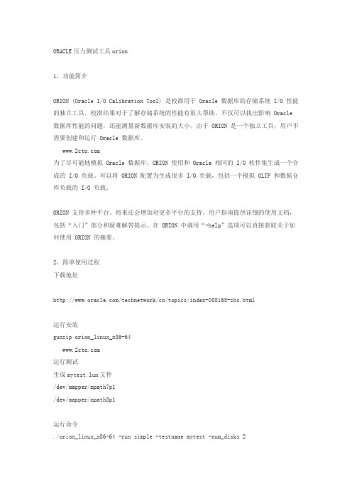
2,简单使用过程下载地址/technetwork/cn/topics/index-088165-zhs.html运行安装gunzip orion_linux_x86-64运行测试生成mytest.lun文件/dev/mapper/mpath7p1/dev/mapper/mpath8p1运行命令./orion_linux_x86-64 -run simple -testname mytest -num_disks 2其它方式的命令可以寻求帮助./orion_linux_x86-64 -help3,测试结果[root@dtydb5 tmp]# cat mytest_20120629_1519_summary.txt ORION VERSION 11.1.0.7.0Commandline:-run simple -testname mytest -num_disks 2This maps to this test:Test: mytestSmall IO size: 8 KBLarge IO size: 1024 KBIO Types: Small Random IOs, Large Random IOsSimulated Array Type: CONCATWrite: 0%Cache Size: Not EnteredDuration for each Data Point: 60 secondsSmall Columns:, 0Large Columns:, 0, 1, 2, 3, 4 Total Data Points: 15 Name: /dev/mapper/mpath7p1 Size: 536869863424 Name: /dev/mapper/mpath8p1 Size: 5368698634242 FILEs found.Maximum Large MBPS=183.53 @ Small=0 and Large=4 Maximum Small IOPS=851 @ Small=10 and Large=0Minimum Small Latency=11.38 @ Small=3 and Large=04,结果比较分析在压力测试的同时,通过IOSTAT命令也可以简单计算数值,由于采样原因,最大值稍有不同。
水冷说明书ORION中文

外观
各部名称
外观
9
各部名称
操作板的名称及机能
操作板的名称及机能
①数字显示部 ②冷却器运转灯
③
冷却器运转开关
④
复位开关
⑤设定开关
⑥温度调节开关
测定水温显示(通常显示) 警报(错误)显示(闪烁)
灯亮:运转
灯灭:停止 在运转或停止冷却器时按动。
在解除警报(错误)时按动。
轻轻按动:可确认设定水温。 按 2 秒以上:可变更设定水温。 *在数字显示部显示设定水温,灯闪烁。 改变设定水温时按动。
接触到设备内部,会导致触电。
产品和机械室内,不要淋水。
而且不要用水洗,否则会导致触电或火灾等。
不要损坏或加工电源线
电源线上放置重物,或过热,或牵拉,或挤压,都会导致电源线损坏,从 而引发触电或火灾等。
异常是要停止运转,向销售店或专业人员咨询。
异常状态下继续运转,会导致触电或火灾等。
漏电断电器工作时,请向专业人员咨询。
(参照「■泵的运转方法」) 5.循环水槽的水,排掉配管内的空气,之后水压计指示上升,压力稳定下来。 6.在压力稳定之后,通过旁通阀,调整到使用压力。
(参照「■送水压力的调整」)
●水位的确认
●水槽即使满水,也有时混入空气。这时候启动冷却器,可能不能冷却。 ●水槽内装有溢流开关,水位达到设定以下时,数字显示为「E03」,发出警报信号。
压送泵水回路(冷却水排放口及旁通阀)的全封闭运转是严格禁止的。全封闭运转的话,压 力会超过 1.2MPa,会使过滤损坏,而且由于泵的故障及泵体发热,会导致配管变形和水的泄 露。 3.对开关频繁低进行 ON/OFF 操作,有可能引发故障。停机之后再启动时,请经过 3 分钟以上 时间。在 3 分钟以内启动运转的话,安全装置起保护作用,还会导致压缩机故障。 4.泵的空运行也是严格禁止的。水槽内必须加水,在确认水位之后再实施运转。 5.排水之际,请将冻结放置模式 OFF。因为泵的空运转会导致故障。 6.水要经常保持清洁,每一个月进行一次水回路检查。必要时,情换水。 (请参照「冷凝器过滤清扫」) 7.对冷凝器过滤,每一个月清扫一次。 (请参照「冷凝器过滤清扫」)
Orion_2111LL中文操作说明书(1206)

Orion 2111LL操作指南目 录第一章概要....................................................I-1简介....................................................I-1特点....................................................I-2工作原理................................................I-3标定原理................................................I-5仪表结构图..............................................I-7术语表: 奥立龙 2111LL 钠表..............................I-8第二章 仪表的准备..............................................II-1仪表拆箱................................................II-1仪表的安装和管道的连接..................................II-2电气接线................................................II-4 安全须知............................................II-4 危险标签及其位置....................................II-5仪表接线................................................II-6接线端子定义............................................II-8试剂和扩散管的安装......................................II-9新钠电极的活化和安装....................................II-11温度补偿电极的安装......................................II-11新参比电极的安装........................................II-12第三章仪表的操作..............................................III-1仪表显示模块的说明......................................III-1仪表各按键的说明........................................III-2设置菜单中各项参数的设置................................III-3停机和启动的操作步骤....................................III-28第四章标定...................................................IV-1标定时各阀门的位置.....................................IV-1流通池的运行..........................................IV-2 清洗流通池.............................................IV-3空气调节...............................................IV-4标定前的注意事项.......................................IV-5进行DKA 标定...........................................IV-6使用其它浓度的标准液进行DKA 标定.......................IV-11准确度检查.............................................IV-12离线标定...............................................IV-13第五章 仪表的维护...............................................V-1每周维护.................................................V-1每月维护.................................................V-2每年的预防性维护.........................................V-5第六章 故障排除.................................................VI-1斜率问题.................................................VI-1序列号和软件版本号.......................................VI-3故障排除表...............................................VI-4错误/事件代码............................................VI-7主机复位.................................................VI-9附录....................................................A-1安装尺寸.................................................A-1默认的离子电极的参数.....................................A-2仪表的技术参数...........................................A-3移液枪的操作.............................................A-7移液枪的使用技巧.........................................A-8目录第一章 概 要本说明书包含了奥立龙2111LL微钠表的操作、维护及故障排除。
Orion Cobalt CO104D 子式音箱说明书

CO104D SubwooferMODELMCO104S CO104D CO124S CO124D CO154S CO154DWHAT’S IN THE BOXIncluded in this box are all the necessary mounting hardware and cables for your basic installation. Listed below is a detailed list of the components included in this system package.Quantity Description1 Installation and Operation Manual1 Orion™ Cobalt woofertemplate1MountingscrewsMountingINSTALLATIONThe performance of these Cobalt subwoofers is directly proportional to the quality of the installation. Care taken with the installation process will be rewarded by years of satisfying performance. If you are unsure of your installation abilities, please refer to your local authorized Orion dealer for assistance. Orion dealers are trained professionals dedicated to extracting the maximum performance out of your Orion system. If you decide to install this speaker system yourself, please read the entire section on sealed and vented enclosures before starting the installation.TOOLS OF THE TRADEListed are the majority of the tools required to perform the installation. Having the proper tools will make the installation much easier. It is very difficult when you get half way through the installation and discover that you require a specific tool to get yourself through a particular part of the installation. Some of these tools are necessities. Some make the job much easier.•Marking Pen•Electric Drill and assorted Bits•Phillips Screwdriver•Wire Strippers•Allen Wrenches•Volt/Ohm Meter (Optional)•Table Saw•Jig Saw•Wire Cutters•Wire CrimpersFINDING SPEAKER MOUNTING LOCATIONSChoosing the correct speaker locations will have the greatest effect on the sound quality of the system. Different considerations are needed when choosing the locations that best suit your needs. The locations must be large enough for the speakers to fit. Care is needed to ensure that the location you have chosen will not affect any of the mechanical or electrical operations of the vehicle.Determining the best location for the speakers will depend on your cosmetic needs and your vehicle's interior. If minimal intrusion in your vehicle is desired, factory speaker locations may be the ticket for you. These woofers are too large to fit most factory locations and typically need enclosures to perform correctly.FEATURES1 Polypropylene dust cap - moisture and UV resistant.2 Oversized NBR (Nitrile-butadiene Rubber) surround for linear controlled long excursion.3 Vented paper cone - moisture and UV resistant.4 Custom stamped steel frame.5 Vented Kapton voice coil former (10” & 12" uses 1.5" voice coil former, 15” use a 2" voice coil former).6 9mm steel front plate.7 Large 2 stack ceramic magnets.8 8mm steel back plate/pole piece T yoke assembly.9 0.75" vent. Part of the enhanced voice coil cooling system (forced convection).10 PVC magnet protector.11 High temperature Copper 4 ohm voice coil.12 Venting in voice coil former. Part of the enhanced voice coil cooling system (forced convection).13 Interlaced Conex spider with stitched and looped tinsel leads attached. 14 Push Terminals.15Reversible PVC mounting gasket.131215141110912365748WIRING CONFIGURA TIONSThe following illustrations provide guidelines on properly connecting your Orion Cobalt woofer to an Orion Cobalt amplifier for maximum performance.Recommended Amplifier PowerContinuous Power (RMS)Peak Power (Watts) 1 woofer 100 to 300 200 to 600 2 woofers 200 to 600 400 to 1200 3 woofers 300 to 900 600 to 1800 4 woofers400 to 1200800 to 2400Parallel—Two Speakers ( 4 ohm voice coils)Two 4 ohm voice coil woofers with the two woofers in parallel results in a 2 ohm load to the amplifier.1.Connect the speaker in parallel by connecting the two positive (+) terminals together and the two negative (-) terminals together.2.Wire the positive (+) terminals of the woofers to the positive (+) terminal on the amplifier. Wire the negative (-) terminals of the woofers to the negative (-) terminalon the amplifier.One Speaker (4 ohm voice coil)One 4 ohm voice coil woofer results in a 4 ohm load to the amplifier1.Connect the speaker by connecting the positive (+) terminal of the woofer to the positive (+) terminal on the amplifier. Wire the negative (-) terminal of the wooferto the negative (-) terminal on the amplifier.Series—Two Speakers (Single 4 ohm voice coils)Two single 4 ohm voice coil subwoofers with the voice coils connected in series to result in an 8 ohm load to the amplifier.1. Connect the woofers in series by connecting the negative (-) terminal of the first woofer voice coil to the positive (+) terminal of the second woofer voice coil.2. Wire the positive (+) terminal of the first woofer voice coil to the positive (+) terminal on the amplifier. Wire the negative (-) terminal of the second woofer voice coil to the negative (-) terminal on the amplifier.Series/Parallel - 4 Speakers (Single 4 Ohm Coils)4 single 4 ohm voice coil subwoofers with the voice coils of each pair of speaker wired in series and then all 4 speakers wired in parallel to result in a 4 ohm load on the amplifier.1.Connect the negative (-) terminal from speaker 1 to the negative terminal on speaker 3 and then hook that wire to the negative (-) terminal on the amplifier.2.Connect the positive (+) terminal from speaker 1 to the negative (-) terminal on speaker 23.Connect the positive (+) terminal from speaker 3 to the negative (-) terminal on speaker 44.Connect the positive (+) terminal from speaker 2 to the positive (+) terminal onspeaker 4 and then hook that wire to the positive (+) terminal on the amplifer.Parallel—Two Speakers (dual 4 ohm voice coils)Two dual 4 ohm voice coil woofers with voice coils in parallel and the two woofers in parallel results in a 1 ohm load to the amplifier.1. Connect the speaker in parallel by connecting the four positive (+) terminals together and the four negative (-) terminals together.2. Wire the positive (+) terminals of the woofers to the positive (+) terminal on the amplifier. Wire the negative (-) terminals of the woofers to the negative (-) terminalon the amplifier.Parallel - One Speaker (dual 4 ohm voice coils)One dual 4 ohm voice coil woofer with voice coils in parallel results in a 2 ohm load to the amplifier.1.Connect the speaker in parallel by connecting the two positive (+) terminals together and the two negative (-) terminals together.2.Wire both positive (+) terminals of the woofer to the positive (+) terminalon the amplifier. Wire both negative (-) terminals of the woofer to thenegative (-) terminal on the amplifier.Series-Parallel—Two Speakers (dual 4 ohm voice coils)Note: Verify and ensure that the woofer wiring is connected as shown with the negative connection from the first woofer coil connected to the positive connection of the second woofer coil.Two dual 4 ohm voice coil subwoofers with voice coils in series and then parallel the two series woofers results in an 4 ohm load to the amplifier1.Connect each woofer in series by connecting the negative (-) terminal of the first coil to the positive (+) terminal of the second coil.2.Wire the positive (+) terminal of each woofer's first coil to the positive (+) terminal on the amplifier. Wire the negative (-) terminal of each woofer's second coil to thenegative (-) terminal on the amplifier.Series-Parallel - Four Speakers (dual 4 Ohm voice coils)Note: Verify and ensure that the woofer wiring is connected as shown with the negative connection from the first woofer coil connected to the positive connection of the second woofer coil.Four dual 4 ohm voice coil woofers should be wired with the voice coils on each woofer in series and then parallel the four woofers for a resulting a 2 ohm load to the amplifier.1.Connect each woofer in series by connecting the negative (-) terminal of the first coil to the positive (+) terminal of the second coil.2.Wire the positive (+) terminal of each woofer's first coil to the positive (+) terminal on the amplifier. Wire the negative (-) terminal of each woofer's second coil to the negative (-) terminal on the amplifier.-ENCLOSURE RECOMMENDATIONSEnclosure Details1.External dimensions calculated for 3/4” building material2.Includes speaker displacement3.Volumes given are net tuning volume4.Enclosures include a minimal amount of damping material. Just enough material to line the inside of the enclosure is required.Cobalt CO104S/CO104D Sealed Enclosure RecommendationsExternal DimensionsA = 14 inB = 12.5 inC = 11.5 inInternal DimensionsA = 12.5 inB = 11 inC = 10 inWall ThicknessFront = 0.75 in Side = 0.75 in —Box Parts—Box Shape: Square Prism Top, 1 Bottom:depth (c) = 11.5 in width (b) = 12.5, thickness = 0.75 in1 Front, 1 Back:height (a) = 12.5 in width (d) = 11, thickness = 0.75 in 2 Sides:height (a) = 12.5 in depth (c) = 11.5, thickness = 0.75 in—Driver Mounting—FrontSidesFigure 10 Figura 10 Abbildung 10A = 15.75 inB = 14.25 inC = 12 inInternal DimensionsA = 14.25 inB = 12.75 inC = 10.5 inWall ThicknessFront = 0.75 in Side = 0.75 in—Box Parts—Box Shape: Square Prism Top, 1 Bottom:depth (c) = 12 in width (b) = 14.25, thickness = 0.75 in1 Front, 1 Back:height (a) = 14.25in width (d) = 12.75, thickness = 0.75 in 2 Sides:height (a) = 14.25 in depth (c) = 12,Sides thickness = 0.75 in—Driver Mounting— FrontVent Parts --- Round 1 Duct:outside diameter (e) = 3.2 in inside diameter (g) = 3 in length (h) = 9.5 in Vent Parts --- Square 1 Top, 1 Bottom:width (e) = 3, length (h) = 10 in thickness = 0.125 in 2 Sides:height (g) = 2.75, length (h) = 10 inthickness = 0.125 inSides- OR -VENT SquareFigure 11 Figura 11 Abbildung 11A = 15.5inB = 14.75 inC = 12 inInternal DimensionsA = 14 inB = 13.25 inC = 10.5 inWall ThicknessFront = 0.75 in Side = 0.75 in —Box Parts—Box Shape: Square Prism Top, 1 Bottom:depth (c) = 12 in width (b) = 14.75, thickness = 0.75 in1 Front, 1 Back:height (a) = 14 in width (d) = 13.25, thickness = 0.75 in 2 Sides:height (a) = 14 in depth (c) = 12, thickness = 0.75 inDriver MountingMounting: FrontSidesFigure 12 Figura 12 Abbildung 12A = 18 inB = 16.75 inC = 13 inInternal DimensionsA = 16.5 inB = 15.25 inC = 11.5 inWall ThicknessFront = 0.75 in Side = 0.75 in—Box Parts—Box Shape: Square Prism Top, 1 Bottom:depth (c) = 11.5 in width (b) = 12.5, thickness = 0.75 in1 Front, 1 Back:height (a) = 12.5 in width (d) = 11, thickness = 0.75 in2 Sides:height (a) = 12.5 in depth (c) = 11.5, thickness = 0.75 inDriver Mounting Mounting: FrontVent Parts --- Round 1 Duct:outside diameter (e) = 4.25 in inside diameter (g) = 4 in length (h) = 10 in Vent Parts --- Square 1 Top, 1 Bottom:width (e) = 3.75, length (h) = 10 in thickness = 0.125 in 2 Sides:height (g) = 3.5, length (h) = 10 inthickness = 0.125 inSides- OR -VENT SquareFigure 13 Figura 13 Abbildung 13A = 25 inB = 17.5 inC = 11.5 inInternal DimensionsA = 23.5 inB = 16 inC = 10 inWall ThicknessFront = 0.75 in Side = 0.75 in —Box Parts—Box Shape: Square Prism Top, 1 Bottom:depth (c) = 11.5 in width (b) = 17.5, thickness = 0.75 in1 Front, 1 Back:height (a) = 23.5 in width (d) = 16, thickness = 0.75 in 2 Sides:height (a) = 23.5 in depth (c) = 11.5, thickness = 0.75 inDriver Mounting—Mounting:FrontSidesFigure 14 Figura 14 Abbildung 14External DimensionsA = 25 inB = 17.5 inC = 13 inInternal DimensionsA = 23.5 inB = 16 inC = 11.5 inWall ThicknessFront = 0.75 in Side = 0.75 in—Box Parts—Box Shape: Square Prism Top, 1 Bottom:depth (c) = 13 in width (b) = 17.5, thickness = 0.75 in1 Front, 1 Back:height (a) = 23.5 in width (d) = 16, thickness = 0.75 in2 Sides:height (a) = 23 in depth (c) = 13,Sides thickness = 0.75 inDriver Mounting Mounting: FrontVent Parts --- Round 1 Duct:outside diameter (e) = 4.25 in inside diameter (g) = 4 in length (h) = 7 in Vent Parts --- Square 1 Top, 1 Bottom:width (e) = 4.25, length (h) = 10 in thickness = 0.125 in 2 Sides:height (g) = 4, length (h) = 7 inthickness = 0.125 inSides- OR -VENT SquareFigure 15 Figura 15 Abbildung 15SPECIFICATIONSModel/Part Number CO104S CO124S CO154S Thiele/Small ParametersFs (free-air resonance, Hz) 39.4 35.4 26.8Vas (equivalent compliance, cu. ft.) 0.948 2.127 6.837Vas (equivalent compliance, liters) 26.84 62.786 193.605 Qms (Q, mechanical) 8.477 6.168 7.66Qes (Q, electrical) 0.54 0.641 0.415 Qts (total driver Q) 0.510 0.580 0.394Re (DC resistance, ohms) 3.6 3.6 3.6Z (nominal impedance, ohms) 4 4 4Le (inductance, mh) 2.54 1.71 3.073 Efficiency (1W @ 1M, dB) 86.7 88.3 91.4Xmax (one way linear excursion, in.) 0.406 0.410 0.453 Xmax (one way linear excursion, mm) 10.2925 10.4075 11.5RMS Power Watts 350 350 550 Nominal Power Watts 700 700 1100 MAX Music Power Watts 1400 1400 2200Mms (total moving mass, grams) 113.51 138.6 188.64 Cms (mechanical compliance, mm/N) 0.143381 0.145374 0.186376 Bl (motor strength, Tesla-M) 13.7 13.1 16.6Sd (effective radiating area, sq. cm.) 363.05 551.55 855.3Sd (effective radiating area, sq. in.) 56.273 85.490 132.572 Frequency range (Hz) 39-250 35-250 26-250 Energy Bandwidth Product (EBP) 73 55 65Driver Physical DimensionSpeaker Displacement (cu ft) 0.053 0.067 0.123 Speaker Outer Diameter (inches/mm) 10.28/261 12.44/316 15.47/393 Mounting hole diameter (inches/mm) 9.13/232 10.91/277 13.82/351 Mounting depth (inches/mm) 5.22/132.5 5.61/142.5 6.79/172.5 Magnet Weight (Oz) 50 50 90Basket diameter (inches/mm) 10.16/258 12.20/310 15.16/385 Recommended EnclosuresTypical sealed enclosure (cu. ft.) 0 .75 1 2 Specifications subject to change without noticeSPECIFICATIONSModel/Part Number CO104D CO124D CO154D Thiele/Small ParametersFs (free-air resonance, Hz) 40.537.927.9Vas (equivalent compliance, cu. ft.) 0.971 2.012 5.963Vas (equivalent compliance, liters) 27.4956.99168.844Qms (Q, mechanical) 8.399 6.6527.369Qes (Q, electrical) 0.6700.7460.507Qts (total driver Q) 0.6200.6710.474Re (DC resistance, ohms) 7.27.27.2Z (nominal impedance, ohms) 888Le (inductance, mh) 3.69 2.66 4.90 Efficiency (1W @ 1M, dB) 86.288.190.5Xmax (one way linear excursion, in.) 0.4060.4100.453Xmax (one way linear excursion, mm) 10.2925 10.4075 11.5 RMS Power Watts 400400600Nominal Power Watts 8008001200MAX Music Power Watts 160016002400Mms (total moving mass, grams) 100.98 133.45 200.3 Cms (mechanical compliance, mm/N) 0.146876 0.131938 0.162540 Bl (motor strength, Tesla-M) 16.9517.5222.33Sd (effective radiating area, sq. cm.) 363.05 551.55 855.3 Sd (effective radiating area, sq. in.) 56.273 85.490 132.572 Frequency range (Hz) 40 - 250 37 - 250 27 - 250 Energy Bandwidth Product (EBP) 605155Driver Physical DimensionSpeaker Displacement (cu ft) 0.0530.0670.123 Speaker Outer Diameter (inches/mm) 10.28/261 12.44/316 15.47/393 Mounting hole diameter (inches/mm) 9.13/232 10.91/277 13.82/351 Mounting depth (inches/mm) 5.22/132.5 5.61/142.5 6.79/172.5 Magnet Weight (Oz) 505090Basket diameter (inches/mm) 10.16/258 12.20/310 15.16/385 Recommended EnclosuresTypical sealed enclosure (cu. ft.) 0 .75 1 2 Specifications subject to change without noticeFigure 16Figura 16Abbildung 16CO104S/CO104D CO124S/CO124D CO154S/CO154D Dimensions inches/mm, Dimensions po/mm, Dimensiones plg./mm, Abmessungen Zoll/mm, Dimensioni pollici/millimetri, Dimensões polegadas/mmA 5.22/132.5 5.62/142.8 6.79/172.5B 2.20/56 2.20/56 2.46/62.5C 5.75/146 5.75/146 6.69/170D 9.13/232 10.91/277 13.82/351E 10.28/261 12.44/316 15.47/393。
Orion VCL-T1oP 2 T1 Port FE版产品概述说明书

Product OverviewHow the TDM over Packet (2 T1 Port FE Version) equipment worksHardware HighlightsT1 Clock recovery and synchronization techniques:Purpose of TDM over Packet technologyOrion’s The T1 data streams received on the T1 interfaces are converted by the T1oP engine of the T1oP equipment to Ethernet data packets (of a fixed size) and transported over the Ethernet network with UDP / IP , MEF or MPLS headers. At the receiving end the T1oP reconstructs the original data streams by removing the IP , MEF or MPLS headers and converts the Ethernet data packets back to T1 frames using highly reliable and accurate clock recovery mechanism. The 'VCL-T1oP' (2 T1 Port FE Version) offers the user a choice of standard, T1 to packet and packet to T1 conversion mechanisms that include SAToP and CESoPSN technologies.19-Inch rack mountable 1U form factor (44mm)1+1 Redundant Power Supplies, AC and DC, or AC plus DC.Redundant power supply inputs.00Extended Temperature Range: (-20C to +60C)EMI / EMC ComplaintReal Time battery backed clock with life in excess of 10 YearsPower over Ethernet (PoE) - OptionalAdaptive Clock Recovery (ACLK)Telecom companies and enterprise users can save Recovered Clock (RCLK) / Loop-Timed Clock significant network and equipment cost and generate Asymmetrical (One-Clock and Two-Clock) Clock additional revenue by offering different types of services over Synchronization to an External Clock (ECLK)a single packet-switched infrastructure by the use of T1oP Synchronization to an Internal Clockequipment. The T1oP equipment is also suitable for connecting to Ethernet / packet wireless equipment to Automatic clock priority selection with fall back achieve fast deployment of T1 services over wirelessPlesiochronous Clocking.Ethernet networks. One particular application is to build T1 links with low cost Wireless LAN bridges, replacing expensive TDM / T1 microwave radios.The 2 x T1 over Ethernet (2 T1 Port FE Version) multiplexer may be used to provide legacy TDM services over Ethernet optical fiber, or wireless Ethernet/IP networks.'VCL-T1oP' T1 over Packet (2 T1 Port FE Version) TDM over IP equipment supports transmission of up to 2 x T1 links over IP / Ethernet, MEF or MPLS Pseudo-wire networks.The 'VCL-T1oP' T1 over Packet (2 T1 Port FE Version) TDM over IP equipment, equipped with a powerful ARM-Cortex Processor which provides a highly reliable clock recovery mechanism for low jitter and wander control, even under variable network conditions.2 x T1 Port T1oP (T1 over Packet) TDM over IP equipment is available with various Electrical (10/100BaseT) and Optical (100BaseFX) Ethernet port options which allow the users to implement 1+1 add-drop (Drop-Insert), Ethernet link redundancy (using Port Trunking / Port Bonding) and 802.1p based QoS mechanisms for network optimization.The 'VCL-T1oP' T1 over Packet (2 T1 Port FE Version) TDM over IP equipment also optimizes on the network usage, such that the bandwidth used by the T1oP equipment on the packet network is limited to the corresponding to the number of T1 ports and the time-slots that are being transported over the Ethernet / packet network.2T1 over Packet / TDM over IPKey Features - T1 and T1oP Interface Key Features explained Key Features - System Management, Monitoring and Alarm Interfaces Key Features - Ethernet / IP Network Interface OAM: Operation and Management Ports System Access, Control and Management Options User configurable MTU (T1oP payload) packet size up to 1500 Bytes.Supports 2 independent T1 interfaces.802.1Q Tag based VLANs Supports 1-4095 VLAN IDs.Internal, External, Adaptive, Recovered clock and Supports Packet priority assignment (IP Diffserv / DSCP).Asymmetrical (One-Clock and Two-Clock) options for the T1 UDP-specific “Special” Ethernet type.TDM port synchronization. Automatic clock priority selection In band VCCV ARP .with fall back.Broadcast DAAbsolute and Differential timestamps.Jitter and Wander conforms to G.823 / G.824 and G.8261 and TDM specifications.Supports two Line codes - AMI and B8ZS.Supports three T1 framing modes - Framed ESF, Framed SF and Unframed.Supports IETF-PWE3 (pseudo-wire), SAToP and CESoPSN transport mechanisms.Supports CESoPSN payload mechanism to support the fractional T1 with data rate of 64Kbps to 1.544Mbps (DS0 timeslot level). User configurable data rate from 64kbps to 1544kbps, in steps of 64kbps.CESoPSN payload mechanism feature allows the user to optimize the packet switched network by limiting its usage to the corresponding number of timeslots carried by a T1 channel.Supports SAToP payload mechanism to transport full T1 (transparent to the structure of the TDM frame useful for transporting framed / unframed T1 channels).Supports network latency / packet delay variation / jitter buffer of up to 512ms.Supports IP , MPLS and MEF8 (Metro Ethernet) addressing. RJ45 - 100 ohms balanced T1 interfaces.T1 Local and Remote Loop-back (RLOOP) facility for testing External and diagnostics.Optical (may use any one combination of above mentioned Ethernet Ports )Power over Ethernet (PoE) (available options as above). Meets and exceeds the Telcordia GR-1089-CORE Lighting and Power Contact Protection requirements.RS232 Point-to-point and point-to-multipoint applications based onIP addressing.Supports drop and insert applications.1+1 Ethernet Link Redundancy / Redundant Link Protection. Supports QoS, 802.1q and 802.1p based packet priority. Q-in-Q Tagging.Telnet.Flow Control in an Ethernet Packet Networks (Regulating Traffic)Port / Customer based bandwidth allocation (Port Rate Limiting – Ingress and Egress)DSCP and 802.1Q / 802.1p based packet tagging and prioritizationMPLS, MEF and UDP tagging for Ethernet traffic.Separate IP Address for TDM traffic and equipment managementVLAN tagging for TDM traffic and equipment access / managementVLAN Based Priority (Classifying Services) - VLAN based Priority feature allows the user to assign priorities to different VLANs carrying various types of services / traffic according based on user categories and preferences. The user may highest priority to TDM traffic and Ethernet services on a lower priority. User may also configure which TDM link should be given preference over the other TDM links, when the uplink bandwidth falls below a particular threshold.Flow Control in an Ethernet Packet Networks: (Regulating Traffic) - Flow Control feature allows the user to regulate the Ethernet traffic flow to minimize packet loss due to data bursts.Port / Customer based bandwidth allocation (Port Rate Limiting) - Port based Ingress and Egress Ethernet Rate Limiting allows the use to assigne the bandwidth as per port / service requirements in addition to provisioning traffic by using 802.1Q and 802.1p VLANs and packet priority.Alarm - Dry contact relay alarms are also available at rear of the system to connect the system to an external alarm.NMS (Network Management System) to monitor multiple SFP based (100Base-FX) and Electrical (100Base-units from single Central Location.T) Ethernet port and PoE options Supports system temperature monitoring with High 4 x 10/100BaseT Copper Ports.Temperature threshold and Low Temperature threshold 2 x 10/100BaseT Copper Ports, 2 x 10/100BaseT Ports alarms and SNMP Traps.with PoE.Supports SNMP V2 Monitoring and Traps.2 x 100BaseFX Optical Fiber Ports, 2 x 10/100BaseT Self-test for checking system errors upon system bootup.Copper Ports.Event Logging.2 x 100BaseFX Optical Fiber Ports, 2 x 10/100BaseT Clock Performance Alarms.Ports with PoE.Network Performance Alarms.Network Performance Monitoring and Diagnostics.Online / remote upgrade of firmware.(DB9) Serial Port.10/100BaseT Ethernet Management for In-band remote access.CLI Control Interface (HyperTerminal or VT100).SNMP V2 Traps (MIB File provided).Windows based GUI (Graphical User Interface) for easy configuration, management and access. Ability to monitor multiple units from a single NMS.Password Protection.Typical Application Diagram in Wireless Network(3G/LTE)BTS :Base Trans-receiver Station MSC :Master Switching Center RNC :Radio Network Controller LTE :Long Term Evolution FT1:Fractional T1 FE :Fast Ethernet GE :Gigabit Ethernet PoE :Power over EthernetTypical Application in Wireless Network - 1+1 Link RedundancyTDM over IP / Ethernet - Providing 2G/3G/LTE over an IP CloudVCL-T1oP(2G)TDM over IP / Ethernet - VLAN Based Priority (Classifying Services)Notes:VLAN based Priority feature allows the user to assign priorities to VLANs carrying different types of services / traffic according based on user preferences.The user may configure the TDM traffic on highest priority and Ethernet service (3G data network) on a lower priority. User may also configure which TDM link should be given preference over the other TDM links when the uplink bandwidth decreases below a particular threshold.TDM over IP / Ethernet Port / Customers based bandwidth allocation (Port Rate Limiting)Premium Customer3GVLAN # 20VLAN # 30Notes:Port based Ingress Ethernet Rate Limiting allows the service provider to assigned the bandwidth as per customer requirements and separating their traffic by assigning 802.1Q based VLANs.Technical Specifications T1oP SpecificationsT1 Interface Power Consumption Power Supply Options Max number of T1 Ports Number of Ports 2Max number of logical links Up to 24Synchronization clock -Adaptive Clock Recovery recovery recovery (ACLK) Options-Recovered Clock (RCLK) / Loop-Timed Clock-Asymmetrical (One-Clock and Two-Clock) Clock -Synchronization to anExternal Clock (ECLK) and an Internal Clock -Automatic fall backMax number of Ethernet -2 x FE (100BaseFX) Optical Ports Ethernet (SFP) Ports-2 x 10/100Base-T Electrical Ethernet Ports Or-4 x 10/100Base-T Electrical Ethernet PortsSupported Transport ETF-PWE3, SAToP and Mechanisms CESoPSNSupported PSN (Packet UDP , IP , MPLS and MEF Switched Networks) type QoS 802.1p packet priority Number of PortsNumber of Ports 2(supporting 64Kbps upto 1.544Mbps on each port)Framing Formats Unframed, SF and ESF Line Coding AMI, B8ZSCompliance ITU-T G.703, G.704, G.706and G.732Jitter and Wander Complies to ITU-T G.823,G.824Line Impedance 100 OhmsProtection-Optional Metallic and Longitudinal Protection -ESD protectionPower Consumption<15 Watts (without PoE)PoE 40 Watts per channelDual Redundant1+1 AC power (100 to 240V AC, 50/60 Hz) 1+1 DC (-48V) power (40 to 72V DC) 1+1 DC (-24V) power (18 to 40V DC) AC plus DC (AC + DC), AC or DCEMI/EMC compliant.Ethernet Interface 100BaseFX (Optical) Ethernet Specifications Number of Ports-Optical SFP based(100Base-FX) and Electrical (100Base-T) Ethernet port and PoE options-4 x 10/100BaseT Copper Ports-2 x 10/100BaseT Copper Ports, 2 x 10/100BaseT Ports with PoE-2 x 100BaseFX Optical Fiber Ports, 2 x 10/100BaseT Copper Ports-2 x 100BaseFX Optical Fiber Ports, 2 x 10/100BaseT Ports with PoE.(may use any one combination of above mentioned Ethernet Ports )Electrical 10/100 Auto-negotiation/MDI-X(Auto-sensing), Full-Half Duplex, RJ45 Electrical Connector, PoE (Power of Ethernet) option on 2 x 10/100BaseT PortsProtection ESD protection Optical 100Base-FX (Fast Ethernet),SFPPower over Ethernet (PoE)40 Watts per port PoE Protection Complies with Telcordia GR-1089-CORE Issue 6Specifications and ITU-T K.44 (2012*) specificationsMaximum Frame Size 1500 BytesTypeSFPCompliance-MSA Compliant -RoHS -EMI -ESD -DDMSafetyClass 1 Laser Safety/ IEC-60825 Compliant Bit Rate 100 MbpsWavelength 1310 / 1550 nmDistance550m to 120Kms, as per order Optical ConnectorLCNote:* Excludes 0.76A (300 Ohms) and 0.38A (600 Ohms)and 0.23 (1000 Ohms) AC Power Cross.Command LanguageManagement and Control InterfacesAC Power Supply Specifications 24V DC Power Supply Specifications 48V DC Power Supply Specifications Environment Windows based GUI (Graphical User Interface). Command Line Interface (English text commands). COM Port (RS232 Serial Port).10/100BaseT Ethernet Port (each multiplexer may be assigned an IP address and connected to a LAN / IP network for remote access and management through the 10/100BaseT Ethernet Port for out-of-band configuration, management and access). Telnet. SNMP , V2.Additionally, a Windows based GUI (Graphical User Interface) for easy configuration, management and access.Input AC Voltage110 / 220 Volts AC Range of input AC Voltage 100 V to 240 V AC,50Hz/60Hz.AC Input ConnectorIEC ConnectorPower Supply 24V DCRange of input18V to 40V DC Input voltage reversal protection Provided Under voltage protection < 4.85V Over voltage protection > 5.15VEfficiency at full load > 90% @ 5V/4A(when input voltage-24V)Ripple at full load < 5mVrms Spike at full load< 50mVPower supply -48V DCRange of input-40V DC to -72V DC Under voltage protection < 4.85V Over voltage protection > 5.15VEfficiency at full load > 91% @ 5V/2A(when input voltage -48V)Ripple at full load < 5mVrms Spike at full load < 50mV00Temperature -20C ~ +60C for Operation0 Humidity5% to 95% (at 35C)Non-condensingRegulatory Compliance NMS (with Telnet) OAM port Specifications External AlarmsChassis Mechanical Specification Safety - IEC 60950 Safety - IEC 60950 CE RoHSComplies to ANS/IEC standardsComplies with Telecom Part 68, FCC Part 15 and CISPR 22 Class AEMC EN55022: 1998 + A1 and A2 EMC EN55024,Operation ETS 300 019 Class 3.2 Storage ETS 300 019 Class 1.2Transportation ETS 300 019 Class 2.3Network Interface RJ-45 Ethernet 10BaseT or 100BaseT-TX (auto sensing)Compatibility Ethernet Version 2.0IEEE802.3Protocols supported ARP , UDP/IP , TCP/IP , Telnet,SNMPManagement SNMP , Serial login, Telnet loginDry Contact Relay - 2 Form C Rated upto 72V DC, 1 Amp. 1U High (44mm)19-inch rack-mounting shelfAlso available in Desktop / Table Top Version.Height 44 mm (1U)Depth 260 mmWidth 480 mm (19 inch rack mountable)Weight3 Kgs.Ordering InformationAdd OCXO option if required (Internal)Power Supply Options Gigabit Ethernet SFP Options 1OCXO Add High Stability Timing, Ultra Low NoiseOCXO (oven-controlled crystal oscillator) optional 1AC220 1 x 100-240V AC Power Supply Input 2DC048 1 x (-) 48V DC Power Supply Input 3 ACDC 1 x 100-240V AC Power Supply Input 1 x (-) 48V DC Power Supply Input4AC220R 2 x 100-240V AC Power Supply Input [Redundant] 5DC048R2 x (-) 48V DC Power Supply Input [Redundant]1VCL-EMOD 0193155Mbps Fast Ethernet SFP Transceiver Duplex LC, 1310nm, 15km, SMF 2VCL-EMOD 0194155Mbps Fast Ethernet SFP Transceiver Duplex LC, 1310nm, 40km, SMF 3VCL-EMOD 0217155Mbps Fast Ethernet SFP Transceiver Duplex LC, 1550nm, 80km, SMF 4VCL-EMOD 0156155Mbps Fast Ethernet SFP Transceiver Duplex LC, 1550nm, 120km, SMF 5VCL-EMOD 0243155Mbps Fast Ethernet SFP Transceiver Duplex LC, 1550nm, 150km, SMF 6VCL-EMOD 0171155Mbps Fast Ethernet SFP Transceiver Duplex LC, 1550nm, 200km, SMFAny One Option.Maximum 2 SFPs perCORE UNIT As per Site Requirement.OCXOTechnical specifications are subject to changes without notice.All brand name and trademarks are the property of their respective owners.Revision 2.0 - May 12, 2014Note: 1.SPFs to be added if 100BaseFX (Optical) Ethernet Ports are required.2.Redundant power supply to be added, if required.Cables and Accessories Options 1VCL-HRNS 1229Optical Patch Cord Connectorized Cable [2LC-2LC, 3m, SM] 2VCL-HRNS 1238Optical Patch Cord Connectorized Cable [2LC-2LC, 10m, SM] 3VCL-HRNS 1242Optical Patch Cord Connectorized Cable [LC-FC, 10m, SM] 4VCL-HRNS 1243Optical Patch Cord Connectorized Cable [2LC-2FC, 10m, SM]5VCL-HRNS 1239Optical Patch Cord Connectorized Cable [LC-SC, 10m, SM]6VCL-HRNS 1258Optical Patch Cord Connectorized Cable [2LC-2SC, 10m, SM]7VCL-ECON 1172Connector (Attenuator LC-LC (10 db.))8VCL-ECON 1173Connector (Attenuator LC-LC (20 db.))9VCL-ECON 1186Connector (Attenuator FC-FC (10 db.))10VCL-ECON 1187Connector (Attenuator FC-FC (20 db.))11VCL-ECON 1197Connector (Attenuator SC-SC (10 db.))12VCL-ECON 1198Connector (Attenuator SC-SC (20 db.))As per Site Requirement.。
ORION 奥立龙 150A电导率仪中文说明书

150A电导率仪简易说明书一、标准配置:150A主机1台,电源变压器1个,电导电极1支电导标准液5瓶英文操作说明书1本二、选购附件:011006电导率标准液(12.9ms/cm--25℃)011007电导率标准液(1413us/cm--25℃)011008纯水电导率标准液(100us/cm--25℃)三、注意:①电导电极和标准液的型号会随制造商的配置而改变,请以到货时的为准。
②电导率电极测量的工作温度范围0-100℃,建议适宜温度为0-60℃,不适宜酮类醛类等对电极有腐蚀的有机溶液测量③电导电极与主机连接时,要注意电极接头的凸槽与主机接口的凹槽对准后才能用力将电极推入,不可拧转电极,否则会把电极的针头插坏而不能使用。
平时不用时,也不需将电极拔下④电导电极与主机连接后,要注意将电极的电缆理顺不要弯折,尤其电极接头不要扭折,以防测量信号传送不稳定或标定过程中在出现错误代码E-22,而不能标定⑤电导标准液数值随温度的变化,请参阅英文说明书P8-P9页.建议使用和样品电导率相近的电导标准液校正电极⑥要退出当前的非测量状态,压mode键即可返回到测量模式⑦013005D和013010D电导电极的电导池初始常数约为:K=0.475四、主机自检当用户测量过程中出现问题时,可以执行此步骤以检查是否主机的问题1.先压ON/OFF键关闭主机电源,将电导电极从主机上拔下来2.压住yes键不放,再压一下ON/OFF键打开主机电源,当屏幕上出现2.XX版本号时放开yes键启动自检程序3.主机自动进行硬件检查,屏幕依次出现TEST1,TEST2,TEST 3,TEST 4,TEST 5,TEST 6,TEST 7然后是0,此时要在3秒钟内开始将所有的按键压一遍,以检查按键是否有问题。
(如果用户未在3秒种内开始压按键或某个按键未压将出错误代码E-7)4.上一步操作完成后,屏幕显示“TEST 8”,然后主机自动关机5.如果在以上的操作中出现任何的错误代码如E-7,请参阅英文说明书第37页的故障处理五、仪器设置将电导电极与主机相连,连接主机和电源,按“ON/OFF”键接通电源1.测量模式选择按mode键移动屏幕下端的▼光标,选择测量模式电导(Cond)或盐度(Sal)或固体溶解总量(TDS)2.温度补偿系数选择①按setup(设置键)进入设置模式②屏幕显示“S-1”,压“▲或▼”滚动键选择温度补偿系数“0.0到3.0%/℃”或“---”(测量纯水时启动此非线性温度补偿功能).注意:初始设置建议选择为0.0③按yes(确认键),确认所选择的温度补偿系数④按mode(方式键),回到测量状态3.参考温度选择①按setup键进入设置模式②屏幕显示“S-1”,按yes键直到屏幕出现“S-3”③压“▲或▼”键选择参考温度25℃,按yes键确认选择④按mode键回到测量状态4.自动标定功能选择①按setup键进入设置模式②屏幕显示“S-1”,按yes键直到屏幕出现“S-4”③压“▲或▼”键选择自动标定“ON”(开启)或“OFF”(关闭),按yes键确认选择④按mode键回到测量状态.5.自动打印功能选择⑤按setup键进入设置模式⑥屏幕显示“S-1”,按yes键直到屏幕出现“S-5”⑦压“▲或▼”键选择自动打印功能“ON”(开启)“OFF”(关闭),按yes键确认选择⑧按mode键回到测量状态.六、电导电极校正(一)自动校正法:(P22)注意:(1)150电导率仪可做1至2点自动校正.若做2点校正,就应该从电导率值低的标准液先开始进行,防止交叉污染(2)自动校正仅能使用下列奥立龙标准液:12.9mS(货号:011006),1413uS(货号:011007),100uS(货号:011008)1、按mode键移动屏幕下端的▼光标,选择测量模式电导(Cond)2、按setup键,屏幕显示“S-1”,压“▲或▼”键选择温度补偿系数值为“0.0”,按yes键确认.3、屏幕出现“S-3”时,压“▲或▼”键选择参考温度25℃,按yes键确认.4、屏幕出现“S-4”时,压“▲或▼”键选择自动标定“ON”(开启),按yes键确认.5、屏幕出现“S-5”时,压“▲或▼”键选择自动打印“OFF”(关闭),按yes键确认,再压mode键回到电导(Cond)测量状态.6、将电极插入第1点电导标准液,并轻微搅动一下.7、按cal键开始校正.8、此时会显示主机预设的电导池常数(如:1.0,0.6或0.1)或上次校正后的电导池常数。
Orion 电话交换设备产品说明书

TMVCL-SafeComm 16 T1 Links (48 T1 Ports)(1+1 Automatic Protection Switch)Product Brochure & Data SheetO RION T ELECOM N ETWORKS I NC.RIONTELECOMNETWORKSHeadquarters: Phoenix, Arizona Orion Telecom Networks Inc.20100, N 51st Ave, Suite B240,Glendale AZ 85308Phone: +1 480-816-8672Fax: +1 480-816-0115E-mail:**********************Website: Regional Office: Miami, Florida Orion Telecom Networks Inc.4000 Ponce de Leon Blvd. Suite 470,Coral Gables, FL 33146 U.S.A.Phone: 1-305-777-0419, Fax: 1-305-777-0201E-mail:**********************Website: Product Description:TM The VCL-SafeComm , 16 T1 Links (48 T1 Ports), 1+1 Automatic Protection Switching Equipment may be used to protect upto 16 T1 Links (48 T1 Ports), and provide an alternate communication route to each T1 Link between any two T1 points. In the event of the failure of the primary (Main)T1 communication route, the VCL-SafeComm,16 T1 links (1+1 Automatic Protection Switching Equipment) automatically switches the T1 traffic to a secondary (standby) T1 route.VCL-SafeComm, 16 T1 Links (48 T1 Ports) 1+1 Automatic Protection Switching (APS)The VCL-SafeComm, 16 T1, 1+1 Automatic Protection Switching equipment is available in a 2U high chassis, which may be mounted in any DIN standard,19-Inch rack.This product allows the user to design 1+1 (protected) redundant T1 routes on similar (fiber-fiber), or complementing (fiber-radio) transmission mediums.The criterion for switching between the primary (main) and the secondary (protected / standby) routes is user programmable. Criterion for switching between the primary (main) and the secondary (protected / standby) routes may be Loss-Of-Signal on T1 links, or AIS (All-Ones AIS alarm) condition. The criterion for switching time and recovery time between the primary (main) and the secondary (protected / standby) routes is user programmable.Data transported on the T1 Links is transparent and protocol independent.Applications:Providing 1+1 alternate paths between any two T1 Transmission mediums (active+standby). E.g.:Fiber/Fiber Radio/Fiber Radio/HDSL Fiber/HDSL etc.The user may deploy the VCL-SafeComm, 1, 1+1 Automatic Protection Switching Equipment to provide an alternate communication route between an optical fiber link and a radio link between any two points. In the event of the failure of the primary (optical fiber) link the 1 is automatically switched to the alternate route over the 1 radio, thus ensuring maximum uptime on all such 1+1 protected 1 Links. Once the primary (optical fiber) T1 Link on the optical fiber is restored, the VCL-SafeComm, 16 T1, 1+1 Automatic Protection Switching Equipment automatically restores the communication to the primary (optical fiber) T1 Link. The switching time and restoration criterion is user programmable.Example:16T T T TApplication Diagram:Figure (application) # 1SafeComm 16 T1 Links SafeComm 16 T1 Links(48 T1 Ports)Point-to-Point Application: May be used in a point-to-point configuration to provide 1+1 Protected /Alternate Routing Path between any two points, using diverse (or similar) T1 transmission mediums. Figure (application) # 2TYPICAL STAR CONFIGURATION#B#CPoint-to-Multipoint Application: To provide 1+1 Redundant T1 Link(s) between a single (BSC) location and multiple (BTS) locations using diverse (or similar) T1 transmission mediums.Figure (application) # 3Application to provide resilient (protected) T1 rings over PDH networks:The VCL-SafeComm may also be used in 1+1 redundant (protected) T1 rings on PDH networks using diverse (or similar) T1 transmission mediums.16 T1 APS16 T1 APSRing Protection5 T1s7 T1s9 T1s7 T1s4 T1s5 T1s5 T1s16 T1sSite CTM How It Works - VCL-SafeComm (With Path Protection Switching)During normal operation, VCL-SafeComm sends duplicate traffic across both the working and dedicated protection T1 facilities while continuously maintaining the performance of both links to determine which link shall be utilized.Figure (application) # 4Features & Highlights:Benefits:High density protection switching equipment (upto 16 T1 Links; i.e. 48 T1 Ports)To provide an independent point-to-point, protected T1 Link between two “T1 USER PORTS” on similar (example fiber-fiber), or dissimilar (fiber-radio) mediums To provide 1+1 T1 redundancyRemote system configuration and management interface through "CLI" text based commands using Telnet and GUI (Graphical User Interface)Provide 1+1 Protection Routing / Path between BSC and BTSThese ensure that mission critical voice, data, control and management traffic are properly supported and maintained even during T1 backhaul facility outages. When the primary (working) link fails, the T1 traffic is automatically switched to the standby (secondary) link to ensure maximum uptimeThrough the comprehensive remote configuration and alarm management capabilities of the VCL-SafeComm, 16 T1, 1+1 Automatic Protection Switching Equipment the product may be used to improve network reliability and control Traffic ProtectionAlternate Facility AdvantagesService Differentiation AgreementsIncreased Network Reliability Resilience Media and Path Diversity Remote ManagementAlarm logging and monitoring.Competitive Service LevelBack-haul Network Technology MigrationUser Programmable 1+1 Protection Parameters: Loss Of Signal (LOS) Alarm Indication Signal (AIS) External open/close dry contact signal.Loss of T1 Signal (LOS)Alarm Indication Signal (AIS)External Dry Contacts SignalThis Alarm indicates that a T1 link error has occured.This indicates the External Dry Contacts open/close state.The Loss of Signal condition in a T1 may occur due to:The failure of the T1 Port of the customer premises equipment.Or due to loss of power to the customer premises equipment.Or due to the disconnection of the T1 Cable between theprotection Switch and the T1 Port of the customer premises equipment.User programmable criterion for switching between Active and Standby T1 Links at the customers premises:Security and Password FeaturesSystem Access, Control and Management Options:TelnetSSHCLI Control Interface (HyperTerminal or VT100)SNMP V2 Traps (MIB File provided)Windows based GUI (Graphical User Interface) for easy configuration, management and access.Ability to monitor multiple units from a single NMS.OAM: Operation and Management PortsRS232 Serial PortUSB COM Port10/100BaseT Ethernet for remote access.Security and ProtectionSecured Access via SSH V2Password Protection: Password Protection in compliance with the mandatory clauses of the GR-815-CORE-2 specifications for secured access control.Logging: Maintains a log of all successful and un-successful attempts.Logged information includes the ID and the IP address of the accessing entities.Alerts the administrator if the un-successful logging attempts exceed three.Security Audit: All access logs for up to 30 days are maintained for security audit purposes.Security log entry of any request or activity including that user-ID (including IP address, if applicable), to establish user accountabilityReport Generation / Audit TrailSecurity Administration.Mode of Operation:There are three modes in which the VCL-SafeComm T1, 1+1 Automatic Protection Switch can be configured to operate in:1. AUTOMATIC SWITCHING MODE2. EXTERNAL TRIGGER SWITCHING MODE3. MANUAL SWITCHING MODE.AUTOMATIC SWITCHING MODE:The VCL-SafeComm can be configured to operate in an AUTOMATIC SWITCHING MODE. In the automatic mode, the switch shall automatically switch and re-route the T1 circuits from the MAIN route to the STANDBY route if there is an AIS or a LOS (LOSS OF SIGNAL) alarm, on the MAIN T1 link route.Similarly, in the automatic mode the switch shall automatically switch back and re-route the T1 circuits from the STANDBY route to the MAIN route, upon the restoration of the service on the MAIN T1 link route.All switching parameters and link restoration parameters are user programmable.EXTERNAL TRIGGER SWITCHING MODE:Sometimes the user wants to switch the T1 circuits between the MAIN route and the STANDBY route when some external event occurs.In the EXTERNAL TRIGGER MODE, the user can switch between the MAIN T1 route and the STANDBY T1 route when an external trigger (such as an closed/opened physical contact) is applied to the switch.This unique feature is used by certain radios equipment suppliers, where they apply an external trigger to switch and re-route the T1 circuits between their main T1 radios and standby T1 radios.:MANUAL SWITCHING MODEIn Manual Switching Mode, the user shall use manual Telnet commands to switch the T1 circuits between the MAIN route and the STANDBY route, manually, using Telnet commands.In this mode the AUTOMATIC MODE and the EXTERNAL TRIGGER MODE are both disabled and the manual commands over ride all other modes.Front View AC VersionDC VersionTechnical Specifications T1 Interface:AC Power Supply Specifications Command Line Interface (English text commands)Output voltage of AC Adapter 100 - 240 Volt ACRange of input AC voltage 100 V to 240 V AC, 50Hz / 60Hz.System Input voltage7.5 V DC to 9.0 V DC, DC input polarity protection.Maximum full load output current 2.5 A at 7.5 V DC / 9.0 V DC Input voltage reversal protection Provided in the Card Efficiency at full load> 86%Command LanguageOperations and Maintenance (OAM) InterfacesRS232 serial interface for local terminal accessUSB serial interfaces for local terminal access10/100BaseT Ethernet Interface for remote access over an IP network.DC Power Supply Specifications Number of InterfacesTotal T1 interfaces for Main T1 Links for Primary T1 Links for Secondary T1 Links Line Rate T1 - 1.544 MbpsLine CodeB8ZS, AMI (user programmable)Frame Structure Transparent between the two points of the T1 Links Bit Rate1544 Kbps ± 50 ppm Jitter Tolerance As per ITU-T G.823Output Jitter < 0.05 UI (in the frequency range of 20 Hz to 100 KHz)Pulse MaskAs per ITU (CCITT) Rec. G.703Conformity (electrical)G.703Nominal Impedance100 Ohms, balanced48161616Mechanical Specifications Temperature NMS (with Telnet) XPort Specification Network interface RJ-45 Ethernet 10BaseT or 100BaseT-TX (auto sensing)CompatibilityEthernet Version 2.0 IEEE802.3Protocols supported ARP , UDP/IP , TCP/IP , Telnet, ICMP , SNMP , SSH LEDs10Base-T and 100Base-TX Activity, Full/half duplex Management SNMP , Serial login, Telnet login, SSHEMI Compliance-Radiated and conducted emissions complies with Class B limits of EN55022:1998-Direct and Indirect ESD complies with EN55024:1998-RF Electromagnetic Field Immunity complies with EN55024:1998-Electrical Fast Transient/Burst Immunity complies with EN55024:1998-Power Frequency Magnetic Field Immunity complies with EN55024:1998-RF Common Mode Conducted Susceptibility complies with EN55024:1998Rack mounting Standard 19-Inch. DIN Rack Height 44.00 mm.Depth 260.00 mm.Width 477.00 mm.Weight 4.3 Kg.00Operating 0C to 50CHumidity5% to 95% Non-Condensing Management and Monitoring RS232 serial, USB serial interfaces for local terminal access.10/100BaseT Ethernet Interface for remote access over an IP network. Encrypted Password Protection.Telnet – Remote access over IP links.SSH – Secured remote access using Secure Shell Protocol over IP links.SNMP Traps and NMS for real time remote monitoring and management over an IP network. Automatic Link Test feature link testing at user programmable periodical intervals.Visual I/O status LED Display.Compliance / RegulatoryEMC FCC Part 15 Class 2Safety - UL 1459 Issue 2Operation ETS 300 019 Class 3.2Storage ETS 300 019 Class 1.2Transportation ETS 300 019 Class 2.31.VCL-SafeComm 16T1 Links (48T1 Ports) 1+1 AutomaticProtection Switching (APS) Equipment19" Shelf 2U High Rack-Mount VersionSupports:- upto 48 x T1 Port [100Ω RJ45F][16 for Main T1, 16 for Primary T1, 16 for Secondary T1]- 1 x 100-240V AC Power Supply Input [Adapter Option]- 1 x System Core Cables, Installation, Documentation,System User Manual, System User Manual Disk etc (Set)VCL-1430-APS-16/48T1-1AC220S. No.Part No. Product Description 2.VCL-SafeComm 16T1 Links (48T1 Ports) 1+1 AutomaticProtection Switching (APS) Equipment19" Shelf 2U High Rack-Mount VersionSupports:- upto 48 x T1 Port [100Ω RJ45F][16 for Main T1, 16 for Primary T1, 16 for Secondary T1]- 2 x 100-240V AC Power Supply Input [Adapter Option]- 1 x System Core Cables, Installation, Documentation,System User Manual, System User Manual Disk etc (Set)VCL-1430-APS-16/48T1-2AC2203.VCL-SafeComm 16T1 Links (48T1 Ports) 1+1 AutomaticProtection Switching (APS) Equipment19" Shelf 2U High Rack-Mount VersionSupports:- upto 48 x T1 Port [100Ω RJ45F][16 for Main T1, 16 for Primary T1, 16 for Secondary T1]- 2 x -24V DC Power Supply Input- 1 x System Core Cables, Installation, Documentation,System User Manual, System User Manual Disk etc (Set)VCL-1431-APS-16/48T1-2DC0245.VCL-SafeComm 16T1 Links (48T1 Ports) 1+1 Automatic Protection Switching (APS) Equipment with External Trigger19" Shelf 2U High Rack-Mount VersionSupports:- upto 48 x T1 Port [100Ω RJ45F][16 for Main T1, 16 for Primary T1, 16 for Secondary T1]- 1 x 100-240V AC Power Supply Input [Adapter Option]- 1 x System Core Cables, Installation, Documentation,System User Manual, System User Manual Disk etc (Set)VCL-1430-APS-16/48T1-EXT-1AC2204.VCL-SafeComm 16T1 Links (48T1 Ports) 1+1 AutomaticProtection Switching (APS) Equipment19" Shelf 2U High Rack-Mount VersionSupports:- upto 48 x T1 Port [100Ω RJ45F][16 for Main T1, 16 for Primary T1, 16 for Secondary T1]- 2 x -48V DC Power Supply Input- 1 x System Core Cables, Installation, Documentation,System User Manual, System User Manual Disk etc (Set)VCL-1431-APS-16/48T1-2DC048Technical specifications are subject to changes without notice.Windows is the registered Trademark of Microsoft Corporation, USA.R evision 09 - September 19, 2012S. No.Part No. Product Description 7.VCL-SafeComm 16T1 Links (48T1 Ports) 1+1 Automatic Protection Switching (APS) Equipment with External Trigger19" Shelf 2U High Rack-Mount VersionSupports:- upto 48 x T1 Port [100Ω RJ45F][16 for Main T1, 16 for Primary T1, 16 for Secondary T1]- 2 x -24V DC Power Supply Input- 1 x System Core Cables, Installation, Documentation,System User Manual, System User Manual Disk etc (Set)VCL-1430-APS-16/48T1-EXT-2DC0248.VCL-SafeComm 16T1 Links (48T1 Ports) 1+1 AutomaticProtection Switching (APS) Equipment with External Trigger19" Shelf 2U High Rack-Mount VersionSupports:- upto 48 x T1 Port [100Ω RJ45F][16 for Main T1, 16 for Primary T1, 16 for Secondary T1]- 2 x -48V DC Power Supply Input- 1 x System Core Cables, Installation, Documentation,System User Manual, System User Manual Disk etc (Set)VCL-1430-APS-16/48T1-EXT-2DC0486.VCL-SafeComm 16T1 Links (48T1 Ports) 1+1 AutomaticProtection Switching (APS) Equipment with External Trigger19" Shelf 2U High Rack-Mount VersionSupports:- upto 48 x T1 Port [100Ω RJ45F][16 for Main T1, 16 for Primary T1, 16 for Secondary T1]- 2 x 100-240V AC Power Supply Input [Adapter Option]- 1 x System Core Cables, Installation, Documentation,System User Manual, System User Manual Disk etc (Set)VCL-1430-APS-16/48T1-EXT-2AC220Headquarters: Phoenix, ArizonaOrion Telecom Networks Inc.20100, N 51st Ave, Suite B240,Glendale AZ 85308Phone: +1 480-816-8672Fax: +1 480-816-0115E-mail:**********************Website: Regional Office: Miami, Florida Orion Telecom Networks Inc.4000 Ponce de Leon Blvd. Suite 470,Coral Gables, FL 33146 U.S.A.Phone: 1-305-777-0419, Fax: 1-305-777-0201E-mail:**********************Website: 。
Orion说明书

分辨率
1%LEL
0.1%Vol
1ppm
1ppm
重复性
3%LEL(50%LEL) 5%LEL(满量程)
0.3%Vol(2~25%)
2ppm 或
2ppm 或
读数的 10% 读数的 10%
响应时间 ( 90)*
30 秒
30 秒(0 ~40 ) 3 分钟(-20 ~50 )**
30 秒
40 秒
高报警 10%LEL
如果产品没有按这本说明书中的说明进行使用和养护 则由 MSA 公司作 出的对产品的保证将无效 为了保护您自己和他人 请严格按照本说明书中所 述及的内容进行操作 我们鼓励我们的客户在使用前 或者需要有关使用和维 护方面的额外信息的时候 写信或打电话来告诉我们
注意 由于安全方面的原因 该设备只能由合格人员进行操作 在操作前应彻底 阅读并理解使用说明书 本说明书仅对该仪表作简要的使用介绍 如对使用说明需作进一步的详细 了解 应以外文原版说明书为准
小于 3 小时
防护等级
IP54
防爆标志
EExiad CT4
重量
650 克 镍氢电池包 380 克 碱性电池包
- 1、下载文档前请自行甄别文档内容的完整性,平台不提供额外的编辑、内容补充、找答案等附加服务。
- 2、"仅部分预览"的文档,不可在线预览部分如存在完整性等问题,可反馈申请退款(可完整预览的文档不适用该条件!)。
- 3、如文档侵犯您的权益,请联系客服反馈,我们会尽快为您处理(人工客服工作时间:9:00-18:30)。
1 电池包的安装 当您收到一台新的 Orion 仪表时 首先应安装电池包 电池组的安装步骤如下
向仪表的顶端方向滑动电池包 将电池包摆入仪表的机身 在电池包和仪表的底部和弯角处分别安装两颗螺丝以固定电池包 螺丝应 当是合适的以保证电池包能正确的安装到仪表上 但不要过紧 一旦电池包安装好后 仪表会自动开机
4
2 仪表开机 如果 Orion 仪表处于关机状态 按动开启/关闭/翻页键 使仪表开机 每次开 机仪表会进行如下内容的自检
显示测试发生 液晶显示屏上的每个部分都会瞬间发亮 听到有声的警报 警报灯发亮 显示屏背光发亮 显示仪表内部诊断结果 任何测得的内部错误会出现在显示器上 一旦自我测试完成后 仪表进入测量模式 气体浓度出现在液晶显示屏上 在 此模式 仪表可投入正常使用
6
议使用含有特殊防渗护面过滤器的 MSA 采样管 P/N497600 800332 800333 或 相当的产品 它可以允许气体的渗透 但不允许水的渗透 以防止上述情况的发 生
注 意 气体警报优先于泵的警报 直到气体警报被清除为止 气体浓度的报警 可 燃 气 体 %LEL 报 警 Orion 仪表可用于探测环境中的可燃性气体 当达 到报警设置点 或达到 100%LEL 爆炸下限 浓度时报警声会响起 报警灯闪亮 以及超过浓度的%LEL 指示标志会闪烁 要消除警报 可在浓度下降后 按下更改 /复位按钮 如果浓度仍旧超过报警设置 警报会再次发生 注 意 当可燃性气体指示达到 100%LEL 时 锁定报警电路会锁定可燃性气体 读数并报警 同时有如下现象 警报声响 警报灯闪亮 100 的字样出现在显示屏 上并闪烁 该警报不能用更改/复位按钮进行重新设定 而只能关机才能消除 警告 如果达到了 100%LEL 的报警条件 您可能处于对生命有危险的境地 此时可能会有产生爆炸的充足的气体 氧气 %O2 报 警 Orion 仪表可用于探测环境中氧气总量 两种情况下会启 动警报 缺氧 氧气太多 达到任一上述条件时 警报声响报警灯闪亮超过浓度的 氧气百分比指示标志闪烁 要消除警报 可在浓度下降后 按下更改/复位按钮 如果浓度仍旧超过报警设置 警报会再次发生 有 毒 气 体 的 报 警 Orion 仪表可以探测环境中的一氧化碳 CO 硫化氢 H2S 气体 当达到了一氧化碳和硫化氢的报警设置点 报警声响 报警灯闪亮 一氧化 碳和硫化氢超过浓度的 ppm 浓度指示标志会闪烁 要消除报警 可在浓度下降后 按下更改/复位按钮 如果浓度仍旧超过报警设置 警报会再次发生 短期暴露值 STEL 的 报 警 当由 Orion 仪表测得的气体总量大于 STEL 限制 时 警报声响 报警灯亮 STEL 指示标志闪烁 要清除报警 就进入 STEL 页面 持续按下更改/重新设定按钮直到 STEL 指示标志闪烁 按下开启-关闭/翻页按钮以 清除 STEL 原记录值 STEL 警报是经过 15 分钟的暴露时间后计算出来的 STEL 标志会出现在显示 屏的上端以显示仪器暴露约 15 分钟后的平均值 平 均 时 重 值 TWA 的 报 警 当由 Orion 仪表测得的气体总量大于 8 小时的 TWA 限制时 警报声响 警报灯亮 TWA 指示标志闪烁 要消除报警 就进入 TWA 页面 持续按下更改/重新设定按钮直到 TWA 标志闪亮 按下开启-关闭/翻页按钮 以清除 TWA 原记录值 TWA 警报是经过 8 小时的暴露时间后计算出来的 TWA 标志会出现在显示屏 的上端以显示自 TWA 读数重新设置后暴露的平均值 跳动指示器 液晶显示屏上的跳动指示器每隔 30 秒闪动一次以提醒使用者该 仪表正处于开启和操作中 电池寿命指示 不管选择了哪个页面 电池电量指示会持续显示在液晶显示屏 的上端 当电池的电用完后 电池电量指示会变成空的轮廓 电池警告 电池警告表明在电池完全耗尽前还有 20 分钟额定的操作时间 注意 当电池警告出现时 仪表保留操作的持续时间由下列因素决定
按动开启/关闭/翻页按钮 直到显示屏上平均时重值 TWA 指示亮起 仅 用于装有数据记录包的仪表 显示装有毒性气体探测器的平均时重值 此时如果 要清除平均时重值记录 可持续按下更改/复位按钮直到平均时重值指示标志闪烁 和 CHANGE 标志点亮 再按下开启/关闭/翻页按钮可以清除记录的平均时重值 并且重新开始记录新的平均时重值
三 外观描述 4
四 功能和操作 4
五 电 池 包 的 充 电 和 更 换 8
六 设 置 9
接通电源
等待 30S
测量
等待 30S
翻页 峰值等ຫໍສະໝຸດ 30S翻页 最小值等待 30S 等待 30S
翻页
短期暴露值 翻页
平均时重值
以下仅限于装 有数据记录的 仪器
等待 30S
翻页 时间
等待 30S
翻页 日期
翻页
3 仪表的使用 按上所述仪表进入测量页面后 可以就仪表储存的一些数据进行查询和调整
按下开启/关闭/翻页按钮 显示屏上峰值指示亮起 仪表显示从最后一次 打开起记录得到的峰值 此时如果要清除峰值记录 可持续按下更改/复位按钮直 到峰值指示标志闪烁和 CHANGE 标志点亮 再按下开启/关闭/翻页按钮可以清除
警告
所有已经或将要负责使用或保养该产品的人员都应该仔细阅读 本说明书 象许多复杂的设备一样 该仪表只有在按制造商的说明 要求进行使用和维护下才能按设计要求进行工作 否则它将不能按 照设计要求进行工作 同时依赖于该设备提供安全保障的的人员可 能会有人身伤亡的危险
如果产品没有按这本说明书中的说明进行使用和养护 则由 MSA 公司作 出的对产品的保证将无效 为了保护您自己和他人 请严格按照本说明书中所 述及的内容进行操作 我们鼓励我们的客户在使用前 或者需要有关使用和维 护方面的额外信息的时候 写信或打电话来告诉我们
按动开启/关闭/翻页按钮 直到显示屏上短期暴露值 STEL 指示亮起 仅 用于装有数据记录包的仪表 显示装有毒性气体探测器的短期暴露值 此时如果 要清除短期暴露值记录 可持续按下更改/复位按钮直到短期暴露值指示标志闪烁 和 CHANGE 标志点亮 再按下开启/关闭/翻页按钮可以清除记录的短期暴露值 并且重新开始记录新的短期暴露值
按动开启/关闭/翻页按钮 直到显示屏上日期指示亮起 仅用于装有数据 记录包的仪表 以月/日/年形式显示目前的日期 此时如要改变日期 持续按下 更改/复位按钮直到 MM/DD/YY 指示标志闪烁和 CHANGE 标志点亮 按下开启-关 闭/翻页按钮使月份单独出现 按动更改/复位按钮使月份变化 当调整正确时 按 一次开启-关闭/翻页按钮使日单独出现 按动更改/复位按钮使日期变化 当调整正 确时 按一次开启-关闭/翻页按钮使年单独出现 按动更改/复位按钮使年份变化 当调整正确时 按下开启-关闭/翻页按钮退出日期设置模式
OrionR 便携式多种气体检测仪
操作使用说明书
根据部件编号 10021555 OrionR Multigas Detector (L) Rev 2 Operating Manual 原版说明书翻译
中美合资无锡梅思安安全设备有限公司
WUXI MSA SAFETY EQUIPMENT CO.,LTD.
七 标 定 10
八 质 保 安 全 指 导 和 故 障 处 理 11
九 附 录 14
2
一 简介
OrionR 便携式多种气体检测仪是美国 MSA 原装进口仪表 它可同时检测工作 场所内的可燃性气体和蒸汽 氧气 一氧化碳气体以及硫化氢气体 当检测到气体 浓度超过仪表设定报警浓度时 仪表会发出声 光报警信号 该检测仪功能强大 操作简单 带背光的显示屏能同时显示四种气体的浓度 显示字体大而清晰 其外 壳坚固 抗跌落 具有优良的防水 防尘功能 可在最恶劣的环境中工作 该检测 仪使用电池包供电 可分为镍氢可充电电池包和碱性电池包 有扩散式和泵吸式两 种采样方式可选 并可选装数据记录功能组件
注意 由于安全方面的原因 该设备只能由合格人员进行操作 在操作前应彻底 阅读并理解使用说明书 本说明书仅对该仪表作简要的使用介绍 如对使用说明需作进一步的详细 了解 应以外文原版说明书为准
1
目录
一 简 介 3
二 规格及性能
3
5
记录的峰值 并且重新开始记录新的峰值 按动开启/关闭/翻页按钮 直到显示屏上最小值指示亮起 仪表显示从最
后一次打开起记录得到的最小值 仅用于氧气探测器 此时如果要清除最小值记录 可持续按下更改/复位按钮直到最小值指示标志闪烁和 CHANGE 标志点亮 再按下 开启/关闭/翻页按钮可以清除记录的最小值 并且重新记录记录新的最小值
ZERO 零点指示 仪表自检完成后 闪烁 10 秒 CAL 标定指示 CHANGE 改变 PUMP 泵故障警报 MM 月份指示 DD 日指示 YY 年指示 TIME 时间 PEAK 峰值 MIN 最小值 STEL 短期暴露值 TWA 平均时重值 %LEL 可燃气 LEL 值读数 %O2 氧气浓度读数 PPM CO 一氧化碳浓度读数 PPM H2S 硫化氢浓度读数 电池电量指示器 表示电池电量 沙漏 请等待 2 按键 为了防止误操作 按键被设计的需要用较大的力操作 当一个按键被正确按下 时 仪表会发出按键提示音告诉使用者 ON/OFF/PAGE 开启/关闭/翻页键 CHANGE/RESET 更改/复位键
OrionR 便携式多种气体检测仪手持使用 便携可靠 体现了当今国际仪表的发 展潮流 实为一种用途广泛 性能可靠的新一代便携式安全仪表
二 规格及性能
项目
参数
检测气体
可燃气
氧气
一氧化碳
硫化氢
探头类型
催化燃烧 (抗中毒)
电化学
电化学
电化学
探头寿命
2年
2年
2年
2年
量程
0~100%LEL
0~25%Vol
0~999ppm 0~200ppm
时间 典型的传送时间如下
5 英尺采样管
3秒
10 英尺采样管
7秒