FXJ-500聚氨酯水力旋流器说明书
KJ2ⅡB ZYJ-500说明书(用于泵站2BFⅡA)
ZYJ-500 型煤矿带式输送机自控液压张紧装置说明书
速接头座;Ф19 通径-3m 胶管的两头分别与蓄能器上的接头座和油缸上通往有 杆腔的接头座连接;Ф19 通径-10m 胶管的一端与泵站上的另一接头座相连,胶 管另一端与油缸上通向无杆腔的接头座连接。各胶管插入接头座时,必须装入 U 形卡,以防出现高压油伤人事故。
1)可实现张紧力任意调节,完全可以实现启动张紧力为正常运行张紧力 1.3-1.5 倍的要求。
(2)响应快。带式输送机启动时,输送带在应力波的作用下处于振荡状态, 此时,张紧装置通过张紧油缸及蓄能站的快速响应保证输送带张紧力基本恒定, 从而使带式输送机启动时平稳、可靠,避免“打带”和过张紧现象,同时减少了 “飘带”和断带事故的发生。
图 1.3 电气开关面板图
第4页
ZYJ-500 型煤矿带式输送机自控液压张紧装置说明书
2.1 工作原理
2.使用手册
图 2.1 为张紧装置的液压系统原理图。
为满足带式输送机对拉紧力起动时大,正常运行时小的要求,液压系统可
相应地提供高(由溢流阀 3
控制)和低(由 YJ1、YJ2
压力继电器控制)两种油
压。为此,首先需将各溢
产品概述
ZYJ-500 型带式输送机用液压张紧装置说明书
目录
1 安装手册
1.1 设备安装及连接 .................................... 1
1.2 现场调试 .......................................... 3
2 使用手册
2.1 工作原理 .......................................... 5
液压张紧系统一直执行上述三项内容,除非按下 SB2“停止”(或者远控停 止)按钮。当按下该按钮,系统退出运行转入待命停机状态。 (7)系统压力点整定
A-T Controls WE-500系列电动阀门操作与安装手册说明书

VALVES & ACTUATORS (513) 247-5465 Fax (513)247-5462On/Off Control Table of Contents:General 1.0Actuator Mounting 2.0Power Requirements 3.0Duty Cycle 4.0Manual Override 5.0Electrical Connection 6.0Limit Switch Settings 7.0Lubrication 8.0Mechanical Position Indicator 9.0Maintenance 10.0Storage 11.0Trouble Shooting 12.0Standard Specifications 13.0Contact Information 14.0VALVES & ACTUATORS (513) 247-5465 Fax (513)247-5462On/Off Control1.0 GeneralWE-500 Series electric actuators are designed to provide reliable and efficient operation of 90º quarterturn valves and dampers.Warning: Use caution when working in, with, or around valves and actuators. High pressures, forces,voltages and flammable media can be present.Warning: Failure to follow instructions for proper electrical wiring, storage, set-up and maintenance maycause serious injury, damage equipment, or void warranty.Pre-Installation InspectionVerify the actuator nameplate to ensure correct model number, torque, operating speed, voltage andenclosure type before installation or use.It is important to verify that the output torque of the actuator is appropriate for the torque requirements ofthe valve and that the actuator duty cycle is appropriate for the intended application.2.0 Actuator MountingThe actuator may be mounted in any position.WE-500 Series actuators are supplied with a female drive output. ISO5211 bolt patterns are providedfor the actuator mounting.It is mandatory that the actuator be firmly secured to a sturdy mounting bracket or directly mounted tothe valves ISO mounting pad. High tensile bolts or studs with spring locking washers must be used.The valve output stem must be in line with the actuator output drive to avoid side loading of the stem.To prevent backlash, no flexibility in the mounting bracket arrangement should be present.2.0 Power RequirementsConsult the nameplate of the actuator (or product data sheet / catalogue) for duty cycle, voltage andcurrent draw information.4.0 Duty CycleDuty cycle rated IEC34 - S2 (35%)Exceeding the actuator's rated duty cycle may cause thermal overload.Because the actuator does not have mechanical limit stops, be careful not to rotate past the valves full openRotate the OLS cam CCW towards the limit switch lever until the switch 'clicks'. Tighten setscrew with The WE-500 series actuators are totally enclosed units with permanently lubricated gear trains (Moly EPWE-500 Series Electric ActuatorOn/Off ControlVALVES & ACTUATORS 9955 International Blvd. Cincinnati, Ohio 45246(513) 247-5465 Fax (513)247-546211.0 StorageActuators must be stored in a clean, cool and dry area. The unit shall be stored with the cover installed. If the actuator is mechanically installed but waiting for electrical connections, please ensure suitably rated cable glands or cable entry blanking plugs are fitted.12.0 Trouble ShootingThe following instructions are offered for the most common difficulties encountered during installation and set-up.SYMPTONPROBABLE CAUSE CORRECTIVE ACTIONMotor will not run.Open in control circuitRefer to appropriate wiring diagram and check for continuity.No power available to actuator. Tripped circuit breaker Reset breaker and check for correct rating. Refer to catalogue data.Manual Override is hard to turn.Incorrectly sized actuator Jammed valve Damaged or bent valve stem.Valve gland packing too tight.Refer to catalogue data and compare valve torque requirements with actuator (torque) output. Check for obstacles in the pipeline. Check for mechanical damageValve only opens or closes partially with motor.Limit switch incorrectly set Over torque:Incorrectly sized actuator Jammed valve Damaged or bent valve stem.Check setting and reset if necessary. Check to see if motor runs when disconnected from the valve. If so, refer to catalogue data and compare valve torque requirements with actuator (torque) output. Check for obstacles in the pipeline. Check for mechanical damageManual Override does not operate valve.Damaged manual override mechanism Check for mechanical damage, replace parts as necessary. Motor runs but does not operate valve.Stripped gearing Damaged actuator / valve linkage.Check for mechanical damage,replace parts as necessary. Check for mechanical damage, replace parts as necessary.WE-500 Series Electric Actuator On/Off ControlVALVES & ACTUATORS 9955 International Blvd. Cincinnati, Ohio 45246(513) 247-5465 Fax (513)247-546213.0 Standard SpecificationsEnclosure Rating Weatherproof IP67Enclosure High-grade aluminum alloy, hard anodizedPower Supply 110/220VAC 1 PH 50/60Hz, 24v AC/DCDuty Cycle Motor EC 34 S2 (35%)Motor Squirrel caged induction motorLimit Switches 2 x open/close SPDT, 250VAC 10A ratingAuxiliary Limit Switches 2 x open/close SPDT, 250VAC 10A ratingStall Protection Built -in thermal protectionTravel Angle 320-degree +/- 10%Indicator Continuous position indicatorManual Override ‘Spanner type’ manual overrideSpace Heater 2W ceramic housedConduit Entries 2 x M20Lubrication Grease Moly EPAmbient Temperature -20 ºC to + 70 ºCExternal Coating Dry Polyester powder.14.0 Contact InformationFor technical support, please contact the Triac office.A-T Controls product, when properly selected, is designed to perform its intended function safely during its useful life. However, the purchaser or user of A-T Controls products should be aware that A-T Controls products might be used in numerous applications under a wide variety of industrial service conditions. Although A-T Controls can provide general guidelines, it cannot provide specific data and warnings for all possible applications. The purchaser / user musttherefore assume the ultimate responsibility for the proper sizing and selection, installation, operation, and maintenance of A-T Controls products. The user should read and understand the installation operation maintenance (IOM) instructions included with the product, and train its employees and contractors in the safe use of A-T Controls products in connection with the specific application.While the information and specifications contained in this literature are believed to be accurate, they are supplied for informative purposes only. Because A-TControls is continually improving and upgrading its product design, the specifications, dimensions and information contained in this literature are subject to change without notice. Should any question arise concerning these specifications, the purchaser/user should contact A-T Controls.For product specifications go to /A-T Controls, Inc. • 9955 International Boulevard, Cincinnati, OH 45246 • Phone: (513) 530-5175 • Fax: (513) 247-5462 • 。
SJ型水力加压器使用说明书D

水力加压器使用说明书一、概述水力加压器是一种应用于石油钻井、修井作业中的能量转换装置,它改变了钻井作业中靠下部钻铤的重量施加钻压的传统作业方式。
当在地质条件恶劣的地层钻进、大斜度井钻进、套管开窗侧钻或裸眼侧钻水平井或定向井钻进时,它在不消耗额外能量、不需要其它特殊设备的情况下,利用循环钻井液的钻头水眼节流压降,及其在活塞上下端面造成推力的差值给钻头加压。
解决了这些特殊钻井作业中不能靠下部钻铤的重量施加稳定钻压的技术难题。
它有效地改变了下部钻具的受力状态,起到了吸震防跳、实现自动送钻、改善钻头和钻具的工作条件,减轻司钻劳动强度、加快钻井速度、减少井下事故、保证井身质量的目的。
是石油钻井中一项投入小、效果明显、容易操作的实用技术和工具。
二、特点1、它改变了钻头加压方式:用泥浆压能为钻头提供稳定钻压,实现了柔性加压钻进。
改变了钻压调节方法,通过改变水力因素调节钻压大小,可节省部分钻铤、减轻钻机负荷。
有效的改善了钻压与钻速匹配关系,扩大了匹配范围,可在大钻压和高转速下钻进,提高了机械钻速。
减少了起下钻次数,提高了机械钻速。
2、它实现了减震效果“质”的飞跃:水力加压器利用开泵循环时钻头水眼节流压降,及其在活塞上下端面造成推力的差值,给钻头柔性加压。
从而最大限度的吸收了钻柱、钻头的冲击振动,克服了冲击振动产生的高峰荷载,解决了复杂地层钻井作业中吸震、防跳的技术难题、实现了标本兼治。
其减震效果是其它类型的减震器所不能比拟的。
3、水力加压器“人工送钻(加压器复位)—自动加压钻进—再人工送钻-再自动加压钻进,周而复始实现连续不断钻进的操作模式和入井使用时不需要特殊操作和特殊工具的优点。
使其操作十分简便可靠并减轻了操作人员的劳动强度,提高了井身质量。
4、提出了新的防斜、打直工艺理论。
原有的防斜、打直工艺,一般采用高速吊打的方法,这种方法虽然有效,但是在牺牲机械钻速的情况下实现的。
导向钻井系统虽然可靠,但比较复杂,耗费高。
金属工业TH-500单管单管空调终端机的说明书

TH-500SINGLE DUCTAIR TERMINAL UNITT H-500S INGLEDUC TTH-500SINGLE DUCT AIR TERMINAL UNITThe METALAIRE TH-500 is the simplest and most widely used VAV terminal unit. Its basic components are an insulated sheet metal box, round inlet damper , flow measuring device and rectangular outlet. The unit is served by a central air handler and modulates the amount of ‘primary’ cooling air to the space between a minimum set point and the design airflow.When necessary, the METALAIRE TH-500 can be provided with a heating coil on the discharge of the unit to provide for reheat.STANDARD FEATURES■ TH-500 available in 12 unit sizes and TH-ECO-500 available in 10 sizes to handle 30-8900 CFM.■ Variable or constant volume applications.■ 22 ga. galvanized steel casing, mechanically sealed for low leakage.■ Mechanically fastened damper assembly is double layer, 18 gauge equivalent, galvanized steel with integral blade seal. (<1% at 3.0" wg static pressure).■ Optional factory calibrated controls to meet all con-trol strategies.■ Multi-quadrant, averaging flow sensor for highly accurate (+/-5%) flow readings with varying inlet duct configurations after certified balancer has balanced terminal.■ Externally accessible steel balancing taps.■External control cabinet with offset mounting plateis standard.■ 3-beaded inlet connection tube for added rigidity and secure flex duct connections.■ 1/2" thick, dual density (1.5lb / ft 3 min.)fiberglass insulation with edges coated.Meets NFPA 90A and UL 181.■Rectangular discharge with slip and drive cleatduct connection.■Independently tested and certified laboratoryperformance data.■Full range of options and accessories available (heating coils, disconnects, attenuators, etc.).■ Full range of liners / insulation available.TH-500SINGLE DUCTAIR TERMINAL UNITT H-500S INGLEDUC TTH-500 SINGLE DUCT AIR TERMINAL UNIT , COOLING ONLY The standard location for control panel is Right Hand on Model TH.Looking in the direction of airflow, the control panel is on the right.The control panel will overhang the top and bottom of Unit Size 4, 5, & 6, 1" (25.4 mm).Control Panel Mounting Surface width by height is 13 7/8" x 9 3/4".Models TH Unit Size 20 & 24 have rectangular inlet ducts.Air FlowT H-500S INGLEDUC TTH-500 SINGLE DUCT AIR TERMINAL UNIT WITH ELECTRIC HEATWidthThe standard location for control panel is Right Hand on Model TH.Looking in the direction of airflow, the control panel is on the right.The control panel will overhang the top and bottom of Unit Size 4, 5, & 6, 1” (25.4 mm). Control Panel Mounting Surface width by height is 13 7/8” x 9 3/4”.Models TH Unit Size 20 & 24 have rectangular inlet ducts.T H-500S INGLEDUC TTH-500 SINGLE DUCT AIR TERMINAL UNIT WITH INTEGRAL ATTENUATOR AND HOT WATER COILThe standard location for control panel is Right Hand on Model TH.Looking in the direction of airflow, the control panel is on the right.The control panel will overhang the top and bottom of Unit Size 4, 5, & 6, 1” (25.4 mm).Control Panel Mounting Surface width by height is 13 7/8” x 9 3/4”.Models TH Unit Size 20 & 24 have rectangular inlet ducts.T H-500S INGLEDUC T1) AHRI certified data is highlighted while all other data are application ratings 2) Radiated sound is the noise transmitted through the unit casing 3) Sound power levels expressed in decibels, (dB) re 10-12 Watts 4) Min ΔPs is the minimum operating pressure requirement of the unit with thedamper full open and is the static pressure drop from the unit inlet to the unit discharge 5) Performance data based on laboratory tests conducted in accordance with ASHRAE130-2016 and AHRI 880-20176)NC values are calculated using attenuation credits outlined in AHRI 885-2008 Appendix E 7) Blank spaces indicate Minimum Ps if unit exceeds the ΔPs across the unit 8) Sound performance based on units lined with standard dual densityfiberglass insulationRADIATED SOUND MODEL THT H-500S INGLEDUC T1) Leakage testing conducted in accordance with ASHRAE 130-20162) Per ASHRAE Standard 130-2016 “terminal casing leakage: the amount of the air in ft 3/min (L/s) leaking from the terminal unit at a given inlet pressure with the outlet(s) and inlet(s) blocked and with the damper/valve fully opened”3) Per ASHRAE Standard 130-2016 “terminal damper leakage: the amount of air in ft 3/min (L/s) leaking through a fully closed damper/valve of a supply/exhaust terminal unit at a given inlet pressure”opened”PERFORMANCE NOTESTH-500 STANDARD CONSTRUCTION CASING AND DAMPER LEAKAGE ■ Units tested per ASHRAE Standard 130-2016.■ All model sizes certified in accordance with AHRI 880-2017 certification program.■ ETL listed to meet requirements of UL 1995 and CSA 236.■ Dual-density fiberglass insulation meets UL 181 and NFPA 90A/90B.■ Insulation meets ASHRAE 62.1 requirements for resistance to mold growth and erosion.■ Hot water coils are manufactured in accordance to AHRI Standard 410.CERTIFICATIONS AND STANDARDS4) Casing and Damper leakage shall not exceed 1% of the maximum rated airflow at 3” w.g. 5) 4” and 5” inlets are built with 6” casingsT H-500S INGLEDUC TTH-500 HOT WATER COILS MBH SELECTION DATA1) All coil performance in accordance with AHRI Standard 410-20012) Heating capacities are in MBH 3) Performance data based on a temperature differential of 115°F (180°F entering water temperature and 65°F entering air temperature)4) For temperature differentials other than 115°F , multiply the MBH by the correction factors below 5) Head Loss is in feet of water6) Airside ΔPs is the air pressure drop of the hot water coil7) Aire temperature rise =927 x MBH/CFM8) Water temperature drop = 2.04 x MBH/GPM9) Values in tables are listed for 0 ft. of altitude and no glycol in the systemT H-500S INGLEDUC TTH-500 HOT WATER COILS MBH SELECTION DATA1) All coil performance in accordance with AHRI Standard 410-20012) Heating capacities are in MBH 3) Performance data based on a temperature differential of 115°F (180°F entering water temperature and 65°F entering air temperature)4) For temperature differentials other than 115°F , multiply the MBH by the correction factors below 5) Head Loss is in feet of water6) Airside ΔPs is the air pressure drop of the hot water coil7) Aire temperature rise =927 x MBH/CFM8) Water temperature drop = 2.04 x MBH/GPM9) Values in tables are listed for 0 ft. of altitude and no glycol in the systemOutside Diameter (OD) connection size, Inches3 Row4 Row7/8"7/8"7/8"7/8"T H-500S INGLEDUC TTH-500 ELECTRIC HEAT METALAIRE’s electric heaters are factory mounted, ETL listed to meet electrical safety standards and comply with UL 1995 and CSA 236. Electric heaters, as pictured on this page, are integral to the air terminal unit. The discharge end has slip and drive connections for easy connection to downstream ductwork. The heater plenums are an integral attenuator that is lined with the same liner selected for the casing. The integral attenuator also helps to reduce discharge sound. Single duct electric heaters are a side-mounted, slide in style to allow easy field maintenance. The heating elements are designed to minimize hot spots and nuisance tripping of the thermal cutouts. INCLUDED WITH EACH HEATER ASSEMBLY :■ Heater and cabinet mounted on the discharge of the TH-500■ Discharge plenum comes standard with ½” dual density fiberglass lining, optional liners are available ■ Air pressure switch■ De-energizing magnetic contactors per step and backup magnetic contactor■ Magnetic contactors are the standard configuration, optional SCR control is available■ Backup manual reset high temperature limit (disc type)■ Non-isolated transformer■ Slip and drive connections■ Heater is shipped factory mounted and wiredELECTRIC HEATER ASSEMBLY CONSTRUCTION DETAILS■ Electric reheat coils are factory mounted on the discharge of the air terminal. The heaters are ETL listed for zero clearance, and are tested in accordance with UL Standard 1995, CSA-C22.2 No. 236 and the National Electric Code (NEC). Heater casings are constructed of galvanized steel. Element wire is high grade nichrome alloy derated to 45 watts per square inch density. Element wire is supported by moisture-resistant steatite ceramics.■ Ceramics are enclosed in reinforcement brackets spaced across the heater element rack at 2" to 4" intervals. Controls are contained in a NEMA 1 control cabinet with a hinged, latching door. A permanent wiring diagram is affixed to the inside of the control cabinet doorfor field reference.All accessories that can be attached to the Single Duct Boxes are not a part of the AHRI certification program but ratings can be affected by their use.T H-500S INGLEDUC TAll accessories that can be attached to the Single Duct Boxes are not a part of the AHRI certification program but ratings can be affected by their use.TH SOUND ATTENUATORS ■ The optional acoustically lined sound attenuator is designed to further reduce discharge sound levels from the air terminal. The chart below gives reductions to the discharge sound power figures at minimum static pressure for each octave band. ■ Attenuators are integral to the box ■Standard attenuator is 3 ft. (36 inches) long TH-500 RECOMMENDED MIN/MAX AIRFLOW RANGESPERFORMANCE NOTES1) Actual minimum and maximum airflow ranges depend on the transducer differential pressure range and accuracy. 4) Maximum CFM for Pneumatic and Analog controls are based on a sensor differential pressure of 1.00 in. wg.。
华建综保LM500F、510F说明书
TU
UT
TU
UT
1.2 产品特点......................................................................................................................................... 1
UT
TU
UT
4.6 漏电保护....................................................................................................................................... 17
TU
UT
TU
UT
4.7 断相保护....................................................................................................................................... 17
2
目录
1 概述..................................................................................................................................................... 1
TU
UT
TU
UT
4.5 单相接地保护............................................................................................................................... 16
安装短路电流等级-500 500f 509型接触器和起动器说明书
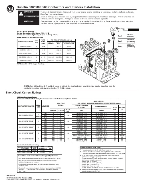
Bulletin 500/500F/509 Contactors and Starters InstallationShort Circuit Current RatingsTo prevent electrical shock, disconnect from power source before installing or servicing. Install in suitable enclosure. Keep free from contaminants.Avant le montage et la mise en service, couper l'alimentation secteur pour éviter toute décharge. Prévoir une mise encoffret ou armoire appropriée. Protéger le produit contre les environnements agressifs.Desconéctese de la corriente eléctrica, antes de la instalación o del servicio, a fin de impedir sacudidas eléctricas. Instálelo en una caja apropiada. Manténgalo libre de contaminantes.NOTE: For NEMA Sizes 0, 1 and 2, if space is critical, the overload relay mounting plate can be detached from the contactor mounting plate by removing the (2) #8-32 screws.High Fault Short Circuit RatingsFor all Catalog Numbers:Control Connections Wire Range: AWG 18 -12Control Connections Tightening Torque: 12 lb-in (1.4 N •m) NOTE: Use 60° / 75° C Copper Wire Only.Renewal Parts and Accessory KitsRenewal Contact Kit for Power Poles (One Pole Per Part No.)Size 0 ……………………………………………………….................................................Part No. 40410-331-51Size 1 ……………………………………………………….................................................Part No. 40410-331-52Size 2 ……………………………………………………….................................................Part No. 40420-322-51Size 3 ……………………………………………………….................................................Part No. 40430-300-51Size 4………………………………………………………..................................................Part No. 40440-300-51 Operating Coil…………...........................................................................................(Specify number and rating on coil label) Auxiliary ContactsSingle circuit (1 N.O.)……………………………………………………...…….........................Catalog No. 595-ASingle circuit (1 N.C.)………………………………………………...…….…….........................Catalog No. 595-BSingle circuit (1 N.C. Late Break) ………………..………………...……...............................Catalog No. 595-BLDouble circuit (2 N.O.)……………………………………………..…...……...........................Catalog No. 595-AADouble circuit (2 N.C.)……………………………………………..…………..........................Catalog No. 595-BBDouble circuit (1 N.O.-1 N.C.)……………………………………….....……….......................Catalog No. 595-AB Power Pole Adder KitSizes 0 and 1…………………………………………………………………..……...............Catalog No. 599-P01ASize 2………………………………………………………………………..….........................Catalog No. 599-P2ASize 3……………………………………………………………………........……...................Catalog No. 599-P3ASize 4……………………………………………………………………....………....................Catalog No. 599-P4ANOTE: Contactor sizes 0, 1 and 2 with 50 Hz coils and all size 3 and 4 contactors require a special coil(coil number ending with the letter “C”) whenever one or two power poles are added.Control Circuit Fusing KitSingle Pole, Rejection Fuse Only………………………………........................................Catalog No. 599-FR04NOTE: When contactor-mounted, each kit occupies the space of one double circuit auxiliary.Surge Suppressor12-120 Volt AC ...............………………………………………………....……..….................Catalog No. 599-K04240 Volt AC ................………………………………………..………..…….........................Catalog No. 599-KA04 Tie Point TerminalSizes 0, 1 and 2.....………………………………………………...……..….…....................Catalog No. 599-TP02Sizes 3 and 4……...……………………………………………...…………..….…................Catalog No. 599-TP34 Control Terminal KitSizes 0, 1 and 2 ..…………………………………………………...……..….…...................Catalog No. 599-CT02Size 3 .............……...……………………………………………...…………..….…...............Catalog No. 599-CT3Size 4 ............................................................................................................................. Catalog No. 599-CT4 Load Terminal Shield for Top Wired ContactorSizes 0, 1 and 2………………………………………………………………………………...Catalog No. 599-TS02Sizes 3 and 4..………………………………………………………………………...............Catalog No. 599-TS34 Top Wiring Terminal Kit (3 terminals)Sizes 0 and 1 ……………………………………………………….……..……….….........Catalog No. 599-TW01Size 2………………………………………………………………….…..……..…..................Catalog No. 599-TW2Size 3………………………………………………………………….……………..................Catalog No. 599-TW3Size 4………………………………………………………………….……....……..................Catalog No. 599-TW4 Timer Attachment KitLeft Hand On Delay……………………………………………...……....…….......................Catalog No. 596-TL32Left Hand Off Delay…………………………………………………..…...….........................Catalog No. 596-TL33Right Hand On Delay……………………………………………..……...….........................Catalog No. 596-TR32Right Hand Off Delay…………………………………………..……...................................Catalog No. 596-TR33NOTE: For size 2 contactors a special coil (coil number ending with the letter “C”) is required with any timer.When ordering specify catalog number and series letter on the device.Note: additional control circuit overcurrent protection may be required. refer to the National Electrical Code.The current rating of the control circuit conductors furnished with this device is 15 amperes for sizes 0 through 3 and 20 amperes for size 4.Maintain this equipment in accordance with guidelines of NFPA-70b, Electrical Equipment Maintenance.。
说明书-QJR-500(630)
免输送带,输送链受冲击断裂,延长设备机械寿命,同时大大改善大功率设备起动瞬间对电网冲击。
1.4.3 破碎机――利用堵转和快速保护,避免机械故障或阻塞造成电动机过热而烧毁。 1.4.4 风机――利用软起动取代旧的传统起动器,减少机械冲击,节省维修费用。 二、技术参数:
序 型号
号
额定电压 (V)
停止时按下前门停止按钮即可,过程与起动时相反,如果设定为软停车则按设定的模式进行。
若按下右侧停止按钮则立即进入停止状态(软停车无效)。 五、各按钮键说明
起动(RUN)-起动按钮键 在起动准备状态下按此键可使电机起动。 停止(STOP)-停止按钮键 电机运行时按此键进入停车。 编程(MODE)-编程按钮键 在停机状态下按此键进入或退出编程状态。 保存(SET)-保存按钮键 数据修改后按此键保存确认。 复位(RST)-复位按钮键 故障复位或参数设定时返回初始界面。 加、减(△、 )-加减按钮键 数据或功能的递加或递减。
使用说明书
QJR 系列 矿用隔爆兼本质安全型真空交流软起动器
电光防爆科技股份有限公司
安全注意事项:
警告!只有专业技术人员允许安装调试 QJR。 警告!必须保证电动机与 QJR 适配,安装时,必须仔细阅读使用说明书,按要求操作。 警告!不允许软起动器输出端接电容器,否则会损坏起动器。 警告!参数修改时,说明书中标明“禁止改动”的参数,不得修改。 警告!软起动器外壳必须牢固接地。 警告!打开起动器前门维修时,必须断开进线电源或前级开关。 警告!用户应根据实际负载进行电压电流的选择。 警告!硬起动仅适用于试车检修时使用。 警告!本体需拿出检修时,先从前门内侧取下车架,检修完毕后应放回原处,防止丢失。 警告!严禁带电开盖。 警告!不得随意更改本安电器参数及元件规格。
FXJ系列聚氨酯旋流器

FXJ系列聚氨酯旋流器旋流除砂器是除砂器与钻井液振动筛的组合体。
设备的主体结构采用上下两块布置,旋流器布置于上部,下部小振动筛为圆振型振动筛,激振器由一台激振电机驱动,使整个筛箱保持整体向前的圆型轨迹振动。
泥浆通过砂泵产生一定的压力和速度,沿旋流器内壁螺旋进入,较粗的颗粒在离心力和重力的作用下沿旋流器内壁螺旋下沉,从底流口排出,落在下面的细目振动筛上分离,其余介质沿旋流器螺旋上升,从溢流口进入第三级分离设备除泥器进一步净化处理。
保证了处理后的泥浆被下一级的设备更好的处理,同时降低了下级设备的工作负荷。
Hydro cycloneHydro cyclone desilter is the combination equipment of the desilter and shale shakerm. The main structure is arranged by the upper and bottom part, the hydro cyclone is installed on the top, the shale shaker is installed on the bottom, the vibration exciter is drive by the vibration motor, it make the whole staining box keep the move on forward track.The mud produce a certain pressure and speed through sand pump, inlet alone the hydro cyclone inwall, under the action of centrifugal force and gravity, the coarser particles sink alone the cyclone wall spiral, and discharged from the overflow port, and slump on the shale shaker screen for separation, the other medium is go up alone the hydro cyclone, and into desilter the third purification treatment through the overflow drain. Ensure the treated sludge was better handle of the next level of equipment, at the same time reduces the lower working load of the equipment.恒联固控克服了原除砂器制造工艺上存在的缺陷,根据颗粒沉降原理生产出新型的旋流除砂器。
- 1、下载文档前请自行甄别文档内容的完整性,平台不提供额外的编辑、内容补充、找答案等附加服务。
- 2、"仅部分预览"的文档,不可在线预览部分如存在完整性等问题,可反馈申请退款(可完整预览的文档不适用该条件!)。
- 3、如文档侵犯您的权益,请联系客服反馈,我们会尽快为您处理(人工客服工作时间:9:00-18:30)。
FXJ-500聚氨酯水力旋流器使用说明书
一、设备说明
1、本产品系按中华人民共和国专业标准DZ/T 0194-1997制造。
2、本产品具有如下结构参数:
型号:FXJ-500
类型:I
内径:500mm
柱体高:350mm
给矿口当量直径:130mm
给矿方式:左右旋
溢流口直径:140mm(设计:140、150、160、180mm四种)
沉砂口直径:50mm(设计:35、50、70、90、110mm五种)
锥角:20°
分离粒度:74~200um
允许最大给料粒度:10mm
给料压力:0.03~0.3 Mpa
处理能力(m3/h)与溢流口径和给料压力成正比,当给料压力为0.1Mpa,溢流口径为150mm时,处理能力为220m3/h。
3、本产品用聚氨酯弹性体材料制作(部分产品外镶铝壳),具有耐磨
性强,重量轻,不为酸、碱、盐溶液腐蚀,不易老化,不易锈蚀等优点。
但不应在高温条件下工作。
4、本产品适用于含固体泥浆(包括低粘度溶液)的颗粒分级、浓缩、
脱泥及水质净化作业,可用于选矿厂的闭路磨矿分级,尾砂输送或用于
井下填充、筑坝时的浓缩,非金属矿及化工原料的粉体制备,油田钻井泥浆的除碴净化,环保废水处理。
二、设备调整、使用
1、旋流器安装完毕,应当用水加压进行试验,在前表所列额定压力下,
确认无渗漏后,方可投料进行生产。
2、聚氨酯旋流器的使用温度不得大于80℃,最低不得小于-30℃。
3、旋流器给料中固体颗粒最大不得超过给矿口窄边宽度的1/10,如有
较多过粗颗粒应预先筛除。
4、旋流器的单台处理能力按下式近似计算:
Q=0.98 KD · dg · dy(10P)1/2 m3/h
dg----给料口当量直径,dg={4/π(1·b)}1/2 cm;
dy----溢流口直径 cm;
P-----给料口压力 Mpa;
KD----旋流器直径修正系数;KD=0.8+1.2/(1+0.1D);
5、单台旋流器的生产能力在小范围内可以通过改变溢流管直径或给
料压力予以调整,若与生产能力要求相差很大(如一倍以上),即应改换旋流器规格。
6、旋流器的溢流与沉砂粒度及数量比通过改变沉砂口直径与溢流管
直径的比值(称作角锥比)予以调整。
但这种调整对闭路磨矿分级旋流器效果不会明显,因为此时的分级产品粒度主要取决于磨矿机的磨矿效果。
三、操作与维护
1、水力旋流器在工作中应尽力保持给料压力和给料浓度稳定不变,这
样方能避免产品粒度波动并获得较高的分级效率。
2、旋流器的易磨损件主要是沉砂嘴。
当沉砂嘴直径增大时,沉砂产率
提高,溢流量减少。
应经常进行检查并适时更换。
3、水力旋流器机组一般勿须设专人就地看管,但须经常巡视给料是否
正常,设备有无磨损、漏浆事故,以及沉砂口是否发生堵塞等情况。