
WTZK-02温度指示控制器说明书
WTZK-02(BWY-02)型
温度控制器
(电力变压器温度测量与控制的专用仪表)
使用说明书
(我厂选用的是杭州富阳仪表有限公司)
杭州华立仪表有限公司
最大插入深度260
图
1 WTZK-02
型温度控制器
一、用途及原理
WTZK-02型温度控制器(BWY-02型温度控制器),适用于测量变压器油温或其他的液体、气体和蒸气的温度,并能在被测温度达到和超过设定值时发出接点信号。
本仪表主要用于500KV A以上的变压器油温的测量和控制。
控制器的主要结构是由温包(感温探头)毛细管和弹性元件组成。
这三个部件构成的密封系统内充灌了感温介质、当被测温度发生变化时,温包内的液体压力随着发生变化,通过毛细管的传递使表头的弹性元件产生一个相对应的位移量,这个位移经机械放大后便可指示出被测温度,并带动微动开关动作输出信号。
二、主要技术参数
1.测量范围:0~100℃
2.指示精确度:1.5级
3.开关特性
(1)开关设定精度:±3℃
(2)开关差:6±2℃
(3)开关额定负荷:AC220V、1.5A
4.温包尺寸:ф14×150
5.温包安装尺寸:外螺纹M27×2
6.表头安装尺寸:3孔ф6 144×210
7.开关在仪表出厂时标准设定值:第一上限55℃
第二上限80℃
如果用户需调整开关设定值,可打开表盖,转动表盘上旋钮设定针即可,然后按原样合上表盖。
三、安装和使用
1.温度设定:打开表盖,转动旋钮设定针即可(一般不用再设定)。
2.接线:打开表盖,将电缆线从引线接点穿入,按图2要求接线。
电缆线推荐使用KW4×1.5控制电缆。
接线后拧紧引线接头处螺母,不得松动。
表盖按原样合好,均匀旋紧四只螺钉。
温控器表头安装前应先完成安装接线和开关设定两项工作。
图2 接线端子板
3.温控器安装
将螺钉穿过隔振板,将仪表固定在仪表板上,多余纺织管部分应盘为ф300mm以上的环圆状,每隔300mm应用护套做适当固定,以免损坏整台仪表。
4.温包安装
温包的插入深度必须≥150mm。
温包安装前应在安装孔内注满变压器油,然后慢慢插入温包并拧紧M27×2安装接头。
安装接头上有一个M18×1.5空心螺栓,其作用是用于调节温包的插入深度,正确的安装方法是全部拧出M18×1.5空心螺栓,在引长管上缠绕填料(如麻丝或生料带等),用户在完全拧紧空心螺栓前调整好温包的插入深度(尽可能选最大插入深度),然后拧紧空心螺栓。
WTZK-03温度控制器说明书
一、用途
WTZK—03系列压力式温度指示控制器(以下简称温控器)是我公司在WTZK—02型温控器的基础上改进设计的新一代温度指示控制器。
主要为大型电力变压器的油温测量及控制而设计,同时也适用于其它设备的温度检测和控制。
二、主要技术参数:
1、 WTZK—03型温控器的防水性能符合GB4208—93《外壳防护的等级分类》中的IP55防尘、防喷水规定。
2、 WTZK—03TH型温控器符合GB/T2423.3—93《电工电子产品基本环境试验规程试验Ca:恒定湿热试验方法》外露零件的防霉性能。
3、在环境温度—10℃~+55℃,相对湿度5%~95%的条件下,温控器能正常工作。
4、温度指示部分(圆形单向刻度)
规格精度等级基本误差
(0~100)℃(0~40)℃ 2.5级±2.5℃(40~100)℃1.5级±1.0℃
(0~120)℃
(0~40)℃ 2.5级±3℃(40~120)℃1.5级±1.5℃
5、测温组件
5.1 温包尺寸:(Φ14×150)mm
5.2 安装螺纹: M72×2 引线密封螺母螺纹M18×1.5
5.2 毛细管长度:最长15m
6、温度控制部分
6.1 设定范围(30~90)℃/(40~110)℃
常闭、常开输出信号由用户自选,但第二上限的设定值必须大于第一上限的设定值。
6.2 标准设定点:K1=55℃K2=80℃(或按用户要求设定)
6.3 设定动作误差: ±2℃开关切换差:(6±2)℃
6.4 控温开关电气参数
AC 250V·3A
DC 24V·3A (均为无感负载)
开关寿命 10×104次
7、温控器系列型号、外形尺寸
WTZK—03:多边形外壳,毛细管从表头下方引出(见图一)
WTZK—03TH:为有防霉、耐潮要求的用户专门设计,表壳喷塑,所有外露件均采用防锈蚀零件。
gwk温度控制器型号说明书

Compact temperature controllers2Overview about thecompact temperature controllersSubject to technical modification without notice!gwk temperature controllers for water, using indirect coolinggwk temperature controllers for water, with direct coolingValues in () optionalThe compact series teco c guarantees an efficient temperature control with water temperatures from 0°C to 225 °C.The units are available in various versions and with a new generation of controllers. The units in modern industrial design stand for high-quality but affordable technology, high availability, user- and service friendliness. The requirements for high energy efficiency, comprehensive process monitoring and industry 4.0 compatibility are also covered by the series.Already in its basic version, the e-device is the preferred solution for many applications, with an excellent price-performance ratio.Basic equipment includes the gwk basicControl micro-processor control with display of set and actualtemperatures, an automatic water refill, automatic mould draining, an energy-saving continuous heat control. For the individualization there are different interfaces, an individual colouration and lettering, mounting on rubber buffers or rails instead of rolls and other important options.The t-units are equipped with the new gwk compactControl controller with fast 32-bit processor. It has an independent display and control unit logotherm developed by gwk itself with a 7-inch touchscreen with intuitive user interface with friendly menu navigation.The top version gwk modulContro l where also the inputs and outputs of different circuit boards can be chosen freely, completes the new controller family of gwk .3Perfect Cooling and Temperature Controlteco cs e – The universal temperature controller for demanding injection moulding1) at 15 °C cooling water and 90 °C resp. 130 °C circuit water temperature 2) not in combination with mould draining function 3) not in combination with leakage stop operation 4) up to 12 kW heating capacity 5) plus front panel made of thermoset plastic 6) not in combination with return stopTemperature controllers water indirect 95 °C,140 °C , 160 °C and 180 °CT e c h n i c a l d a t aS t a n d a r d s p e c i f i c a t i o n /O p t i o n sSubject to technical modification without notice!• = Standard / o = Option / – = notavailable/ Values in () optional• S imple one button operation and digital display • S elf-optimizing basicControl microcontroller with high control accuracy • C ontinuous monitoring of process parameters (limit comparator) • W ear-free energy-saving SSR heating control • O ptional connection for external thermocouple (Fe-CuNi or Pt 100) • Optional interfaces at front panel (analog 0 - 10 V, 0/4 - 20 mA; serial RS 232, RS 422, RS 485, TTY; Profibus; Profinet) • S plash proof electrics • R eady to connect with 3 m long mains cable and CEE socket • H ousing and hood: RAL 7012 basalt grey • S ide panels: RAL 2004 pure orange4•S elf-optimizing microcontroller with high control accuracy•T•I ntuitive operating interface with user-friendly menu navigation•M easuring, indication and monitoring of the flow rate•I ntegrated operating and service information•S torage and recall of process parameters with memory card•W earless, energy-saving solid state heating control•R eturn temperature indication•C ontinuous monitoring of process parameters•O ptional connection for external thermocouple (Fe-CuNi or Pt 100)•O ptional interfaces at front panel (analog 0 - 10 V, 0/4 - 20 mA; serial RS 232,RS 422, RS 485, TTY; Profibus; Profinet)•S plash proof electrics•R eady to connect with 3 m long mains cable and CEE socket 4•H ousing and hood: RAL 7012 basalt grey•S ide panels: RAL 2004 pure orange1) at 15 °C cooling water and 90 °C resp. 130 °C circuit water temperature 2) not in combination with mould drain4) up to 12 kW heating capacity 5) plus front panel made of thermoset plastic 6) not in combination with return stoTemperature controllers water indirect 95 °C, 140 °TechnicaldataStandardspecification/Options5Perfect Cooling and Temperature Controlperior applicationsraining function 3) not in combination with leakage stop operation stopt 95 °C, 140 °C, 160 °C and 180 °CSubject to technical modification without notice!• = Standard / o = Option / – = not available/ Values in () optionalDisplay and control unit logotherm with user-friendly 7-inch touchscreen6teco cs 230 – water temperature controller for high temperaturesgwk temperature controllers, model teco cs 230t 9 are heating and cooling units with indi-rect cooling that are ready for connection and designed for the operation with water as heat transfer medium. The closed water circuit with automatic pressurization allows a safe process temperatures up to 225 °C.• S elf-optimizing microcontroller with high control accuracy • T ouchscreen for log in, control and monitoring of process parameters • I ntuitive operating interface with user-friendly menu navigation • M easuring, indication and monitoring of the flow rate • I ntegrated operating and service information incl. control display • S torage and recall of process parameters with memory card • W earless, energy-saving solid state heating control • R eturn temperature indication • C ontinuous monitoring of process parameters • O ptional connection for external thermocouple (Fe-CuNi or Pt 100) • O ptional interfaces (analog 0 – 10 V, 0/4 – 20 mA; serial RS 232, RS 422, RS 485, TTY; CAN-Bus; Profibus and Varan-Bus) • S plash proof electrics • R eady to connect with 3 m long mains cable and CEE socket • H ousing: RAL 7035 light grey • Side panels: RAL 2004 pure orange1) at 15 °C cooling water 200 °C circuit water temperatureTemperature controllers water indirect up to 225 °CSubject to technical modification without notice!• = Standard / o = Option7Perfect Cooling and Temperature Controlteco cd – Compact temperature controllerswith direct cooling• S elf-optimizing microcontroller with high control accuracy (version t) • T ouchscreen for log in, control and monitoring of process parameters (version t)• I ntuitive operating interface with user-friendly menu navigation (version t) • M easuring, indication and monitoring of the flow rate (version t) • I ntegrated operating and service information (version t) • S torage and recall of process parameters with memory card (version t) • W earless, energy-saving solid state heating control • R eturn temperature indication (version t) • C ontinuous monitoring of process parameters (version t) • O ptional connection for external thermocouple (Fe-CuNi or Pt 100) • O ptional interfaces at front panel (analog 0 - 10 V, 0/4 - 20 mA; serial RS 232, RS 422, RS 485, TTY; Profibus; Profinet) • S plash proof electrics • R eady to connect with 3 m long mains cable and CEE socket 4 • H ousing and hood: RAL 7012 basalt grey • S ide panels: RAL 2004 pure orangeSubject to technical modification without notice!1) at 15 °C cooling water and 90 °C resp. 130 °C circuit water temperature 2) not in combination with mould draining function 3) not in combination with leakage stop operation 4) up to 12 kW heating capacityTemperature controllers water direct 95 °C and 120 °C• = Standard / o = Option / – = notavailable/ Values in () optional T e c h n i c a l d a t aS t a n d a r d s p e c i f i c a t i o n /O p t i o n steco cr– clean, precise, quiet and powerfulBesides special equipment demands that prevent conta-mination of the atmosphere the cleanroom production re-quires a very high reproduci-bility as well as a precise temperature control withclose tolerances. gwk temperature controllers, model teco cr 1602t 9 are 2-circle heating and cooling units with direct cooling that are ready for connection and designed for the operation with water as heat medium. Besides the closed temperature control circuit the temperature controller teco crof stainless steel castors as well as a stainless steel housing with noise absorption. Thus emissions and particle contaminations can be reliably kept below the requested limit values. Particle measure-ments in the cleanroom laboratory of the Rosenheim University of Applied Sciences confirm the suitability for the application in cleanrooms according to EN ISO 14644 for ISO class 6.•S elf-optimizing microcontroller with high control accuracy•T ouchscreen for log in, control and monitoring of process parameters•M easuring, indication and monitoring of the flow rate•S torage and recall of process parameters with memory card•W earless, energy-saving solid state heating control•R eturn temperature indication•C ontinuous monitoring of process parameters•O ptional external sensor connection (Fe-CuNi or Pt 100)•O ptional interfaces at the rear side of the unit (analog 0 – 10 V, 0/4 – 20 mA; serial RS 232,RS 422, RS 485, TTY; CAN-Bus; Profibus and Varan-Bus)•S plash proof electrics•R eady to connect with 3 m long mains cable and CEE socket•S tainless steel housing with fibre-free noise absorption suitable for laboratory use < 60 dbA•I ntegrated low-emission internal cooling of the unit1) at 15 °C cooling water 130 °C circuit water temperature Subject to technical modification without notice!Temperature controller water indirect 160 °C • = Standard89Perfect Cooling and Temperature Controlteco cw – the most cost-effective solution for glycol-free water from 0 to 25 °C• P recise microprocessor control • S imultaneous display of set and actual values • S imple one button operation • O ptional connection for external thermocouple (Fe-CuNi or Pt 100) • O ptional interfaces at front panel (analog 0 - 10 V, 0/4 - 20 mA; serial RS 232, RS 422, RS 485, TTY; Profibus; Varan-Bus) • O ptional flow rate indication • S plash proof electrics • R eady to connect mains cable and CEE socket • H ousing and hood: RAL 7012 basalt grey • S ide panels: RAL 2004 pure orangeTemperature controllers water indirect 0 - 25 °CSubject to technical modification without notice!T e c h n i c a l d a t aS t a n d a r d s p e c i f i c ./O p t i o n s1) at 30 °C cooling water and 10 °C circuit water temperature• = Standard / o= Option / – = not available10The multiple distribution system has beenfor the attachment to tempera-ture controllers to adjust and monitor indivi-dually the flow volume and the returntemperature of parallel connected consu-mer circuits. Thus the system ensures thehydraulic balance in the temperature con-trol circuits with different pressure lossesand ensures an economic and reliabledistribution of the flow rate delivered.The flow rate and the return temperature ofeach circuit is indicated on the central dis-play of the temperature controller.The process monitoring is performed by theadjustment of minimum and maximumlimit values for the flow rate, return tempe-rature and differential temperature percircuit. In addition, process performancesper distribution circuit are displayed. Whenthe tolerance band is exceeded alarm func-tions are activated and displayed. Display and control unit logotherm with user-friendly 7-inch touchscreen11Perfect Cooling and Temperature Control• S imple attachment to temperature controllers up to 4 circuits max. • D isplay, communication, operation via 7" touchscreen of the temperature controllers • C ontinous, maintenance-free and soiling resistant flow rate measurement per distribution circuit • C ommon temperature control and display in the supply line • S eparate temperature control in the return line per circuit • D isplay of process performances per distribution circuit • D isplay and monitoring of the flow per distribution circuit • L imit value setting of the flow per distribution circuit • L imit value setting of the temperature per distribution circuitSubject to technical modification without notice!* teco cs 90t 9, teco cs 140t, teco cs 160t, teco cs 180t 9 but limited to 160 °C **teco cs 90t 18, teco cs 90t 36, teco cd 90t• T hrottle valve for flow volume adjustment and hydraulic balancing per distribution circuit • M onitoring of temperature differences • C orrosion resistant materials • S hut-off ball valve per distribution supplyand return circuitTechnical data at a glanceValues in () optionalC o m p a c t t e m p e r a t u r e c o n t r o l l e r s _G B _10 / 2019 · S u b j e c t t o t e c h n i c a l m o d i f i c a t i o n w i t h o u t n o t i c e !。
BWY(WTYK)-802、803温度控制器说明书中文

感谢您使用本厂产品使用前请认真阅读产品使用说明书目录一、概况 (1)二、工作原理 (5)三、主要技术指标 (5)四、安装及使用 (5)五、注意事项 (10)六、附录Pt100工业铂电阻分度值表 (11)一、概况1、温度控制器根据沈阳变压器研究所制订的JB/T6302《变压器用压力式温度计》标准的命名如下:22、温度控制器根据JB/T9236《工业自动化仪表产品型号编制原则》的要求产品命名如下:2BWY(WTYK)系列温度控制器的成套性和适用性图一 系列温度控制器外形及安装尺寸B W Y (W T Y K )二、工作原理变压器温度控制器(以下简称温控器),主要由弹性元件、毛细管、温包和微动开关组成。
当温包受热时,温包内感温介质受热膨胀所产生的体积增量,通过毛细管传递到弹性元件上,使弹性元件产生一个位移,这个位移经机构放大后指示出被测温度并带动微动开关工作,从而控制冷却系统的投入或退出。
BWY(WTYK)-802A、803A温控器采用复合传感器技术,即仪表温包推动弹性元件的同时,能同步输出Pt100热电阻信号,此信号可远传到数百米以外的控制室,通过XMT数显温控仪同步显示并控制变压器油温。
也可通过数显仪表,将Pt100铂电阻信号转换成与计算机联网的直流标准信号(0~5)V、(1~5)V或(4~20)mA输出。
三、主要技术指标(一)BWY(WTYK)-802、803型1、正常工作条件:(-40~+55)℃2、测量范围:(-20~+80)℃(0~+100)℃(0~+120)℃(0~+150)℃3、指示精确度: 1.5级4、控制性能:①设定范围:全量程可调②设定精确度:±3℃③开关差: 6±2℃④额定功率: AC 250V/3A⑤标准设定值:802:K1=55℃; K2=80℃803:K1=55℃; K2=65℃ K3=80℃5、仪表安装尺寸:详见外形及安装尺寸图(二)BWY(WTYK)-802A、803A型1~5条同上。
WTZK温度控制器的研究及应用

3温度控制 器 的硬 件构成
W T Z K - O . 1 温 控 器 整 个 硬 件 电 路 由控 制 主 板 、 掉 电 保 护 电 路 、 传 感 器 测 温 电 路 、风 机 控 制 电路 、报 警 跳 闸 电路 、 和 电源 等 部 分组 成 [ 2 ] ,硬 件 结 构 框 图如 图2 所示 。
关键 词 :油式 变压 器 ;温度控制 器
中 图分类 号 :T S 4 文献标 识码 :A 文 章编 号 :1 6 7 1 —7 5 9 7( 2 0 1 3 )0 1 1 0 2 0 4 —0 2
1引 言
近 二 十 年 来 ,油 式 变 压 器 得 到 了迅 速 的发 展 。 由于 油 式 变 压 器 较 油 浸 式 变 压 器 显 出更 多 的 优 点 , 它 在 中 、低 配 变 中得 到 了广 泛 应 用 。据 统 计 , 目前 在 我 国运 行 的 油 式 变 压 器 有4 万 多
1 . . . . . 卜~
用 于 对 油 式 变 压 器 的 保 护 , 防 止 其 绕 组 温 度 过 高 而 损 坏 变 压 器 。 此 外 , 它 还 具有 综 合 测 温 和 显 示 功 能 , 可 显 示 三 相 绕 组 的 温度 ( 包 括 最 高 温 度 、整 定温 度 以及 用 户 设 定 的温 度 ) ,能 指 示 超 温 、 超 高 温 、 故 障 状 态 , 通 过 远 距 离 测 量 传 送 数 据 实 现 保 护 。 随 着 计 算 机 控 制 技 术 在 这 方 面 的应 用 ,温 度 控 制 系 统 达 到 自动 化 、 智 能 化 , 比过 去 单 纯 采 用 电 子 线 路 进 行 P I D 调 节 的控 制 效 果 要 好 得 多 。 在 此 ,本 文 介 绍 一 种 以 微 处 理 器 D S 8 0 C 3 9 0 芯 片 为 核 心 作 用 的W T Z K 一 0 . 1 温 度 控 制 器 ,如 图1 。
RYS-BWY-02系列温度指示控制器说明书
RYS—BWY—02系列
温度指示控制器/
变压器温度控制器/主变油温温度控制器安装操作使用说明书
北京瑞亿斯科技有限公司
北京瑞亿斯科技有限公司
温包外形尺寸:Φ14×150 安装螺纹:M27×2
、安装尺寸见(图一)
图一安装结构图
五、安装与使用
、接线:打开接线盒盖,将电缆线穿入接线盒的空心螺栓和接线盒,接(图二)中(
接第一信号控制回路(即:一限),(3)、(4)接第二信号控制回路(即:二限)表壳接地完毕后,螺丝把距形密封圈平整的固定在接线盖与接线盒之间,在接线盖上放入填料,
、设定温度调整:
开启表盖,移动设定指针到所需要的刻度上,合上
表盖,拧紧螺丝。
、使用前先查看控制器的出厂年月,若以超过一年应自行检
控制器使用前,应先检验触点工作是否正常,触点的电压、
、温包必须全部浸入被测介质中,(尽可能使温包插入最大
深度)被测介质应经常流动。
、安装时,毛细管应引直,相距不大于300mm的距离,用
轧头固定起来,毛细管的变曲半径不应小于50mm。
温度指示控制器应垂直安装在没有强烈振动或有隔振装置
的安装板上,温包与表头的高度差应尽可能小。
在遵守本说明使用的前提下,自出厂之日起12个月内,凡属制
造不良而影响温度指示控制器正常使用。
本厂负责免费修理,调换。
图二接线图
北京瑞亿斯科技有限公司。
温度测量仪器说明书.pdf_1694208893.0651798

1Warning!EN61326-1EN60825-11. Safety notices Before using the thermodetector, please read the manual carefully. Do not use any solvent to clean the thermodetector. Safety symbols:Important information prompt for dangerComplies with European CE safety specificationThe instrument complies with the following standards:Do not align the laser to human eyes or reflective surface2. Notes When the ambient temperature changes in a sudden, it is required to place the thermodetector in the environment for 30 minutes , and measure when internal and external temperatures of the thermodetector coincide.Try to avoid any electromagnetic field caused by electric welding and induction heating.Do not place the thermodetector close to or on a high temperature object.Keep the thermodetector clean, and avoid dust from entering the tube.23. Appearance description1. Alarm indicator2. Liquid crystal display3. Laser control key/digital turn down key ▼4. Mode key5. Back-light/digital turn up key ▲6. Infrared sensor induction zone7. Laser indicator8. Measurement trigger 9. Battery cover4. Liquid crystal display description1: Primary display: Displays measured temperature.2: Function indication: MAX (Maximum value)3: Displays the maximum value4: Fahrenheit degree5: Centigrade degree6: Low voltage indication7: Laser indication8: Measurement indication9: Low alarming10: High alarming11: Data hold12: Radiance indication35. Measurement methods1. Set the upper limit of the instrument alarm:Press and hold the Mode key for 2 seconds, to enter instrument setting, and press MODE key to shift to alarm upper limit setting, in this case, Hi is displayed in the instrument function indication zone, and the alarm upper limit is displayed in the zone. Press ▲/▼ key to increase or decrease the alarm value, and long press ▲/▼ key to accelerate the increase or decrease of the set value.2: Set the low alarm value of the instrumentPress and hold the Mode key for 2 seconds, to enter instrument setting, and press MODE key to shift to alarm lower limit setting, in this case, Low is displayed in the instrument function indication zone, and the alarm lower limit is displayed in the zone. Press ▲/▼ key to increase or decrease the alarm value, and long press ▲/▼ key to accelerate the increase or decrease of the set value.3: Set the instrument radiancePress and hold the Mode key for 2 seconds, to enter the instrument setting, and press the MODE key to shift to the instrument radiance setting, in this case, the instrument radiance indication zone flashes. Press the ▲/▼ key to increase or decrease the radiation value, and long press the ▲/▼ key to accelerate the increase or decrease of the set value.44: Set the instrument temperature unitPress and hold the MODE key for 2 seconds, to enter the instrument setting, and press the MODE key to shift to the instrument temperature measurement unit, the unit symbol on the display flashes, and press the ▲/▼ key to change the unit symbol.5: Exit the settingPress the trigger or long press the MODE key, to exit the instrument setting.6: Turn on/off laserPress the key to turn on or off laser, and the instrument will display the laser symbol7:Turn on or off back-lightPress the key to turn on or off back-light.8: Non-contact temperature measurementAim the thermodetector at the object, and hold the trigger, to conduct continuous measurement of temperature. After displaying stably, release the trigger, and the5When holding the trigger, the secondary display of the instrument will display the maximum value of the measured temperature.When the measured value is greater than the upper limit of high alarm or the measured value is less than the lower limit of low alarm, the red alarm indicator will turn on to alarm.6. Target distance ratio (D:S ratio)The thermodetector has a certain visual angle and visual field, as shown in the following figure.The measured target Tube Light-sensitive componentIn order to guarantee the measured object fills in the visual field of the thermodetector, which means the thermodetector only "sees" the measured object rather than other objects. Larger objects may cause larger temperature measurement distances; for smaller objects, the measurement distances must be close. The ratio of measurement distance to the measured target (D:S) is 12:1, as shown in the following figure:677. RadianceThe radiance characterizes the ability of an object to radiate infrared ray. Larger radiance will lead to stronger radiation ability on the object surface.Radiance of the majority of organic matters or metal oxidized surfaces ranges between 0.85 and 0.98. The radiance of the thermodetector is 0.95 by default. During measurement, set the radiance of the instrument the same with the radiance of the measured object. During measurement, please pay attention to the impact of emissivity on measurement results.The following table is the radiance reference table.Measured surfaceRadiance Aluminum Oxidized0.2~0.4A3003alloy (oxidized)0.3A3003alloy (coarse)0.1~0.3Brass Polishing0.3Oxidized0.5 Copper Oxidized0.4~0.80.6Electrical terminalboardHastelloy0.3~0.8 Ferro-nickel Oxidized0.7~0.95Abrasive blasting0.3~0.6Electropolishing0.15Iron Oxidized0.5~0.9Rust0.5~0.7 Iron(casting)Oxidized0.6~0.95Unoxidized0.2Fusion cast0.2~0.3 Iron(casting)passivation0.9Lead Coarse0.4Oxidized0.2~0.6 Molybdenum oxidation0.2~0.68Nickel oxidation0.2~0.5 Platinum black0.9 Steel Cold rolling0.7~0.9Grinding steel plate0.4~0.6Polished steel plate0.1 ZincOxidized0.1 Asbestos0.95 Asphalt0.95 Basalt0.7 Carbon(unoxidized)0.8~0.9 Graphite0.7~0.8 Silicon carbide0.9 Ceramics0.95 Clay0.95 Concrete0.95 Cloth0.95 Glass plate0.85 Gravel0.9519LCD displayColor LCD display D:S12:18. Replacement of battery When battery is low, the battery symbol will light up, in this case, it is required to replace the battery. Open the battery cover with your hands, a nd replace with a new1.5Vx2AAA battery. Refer to the following figure:9.Technical indexes。
温控器说明书
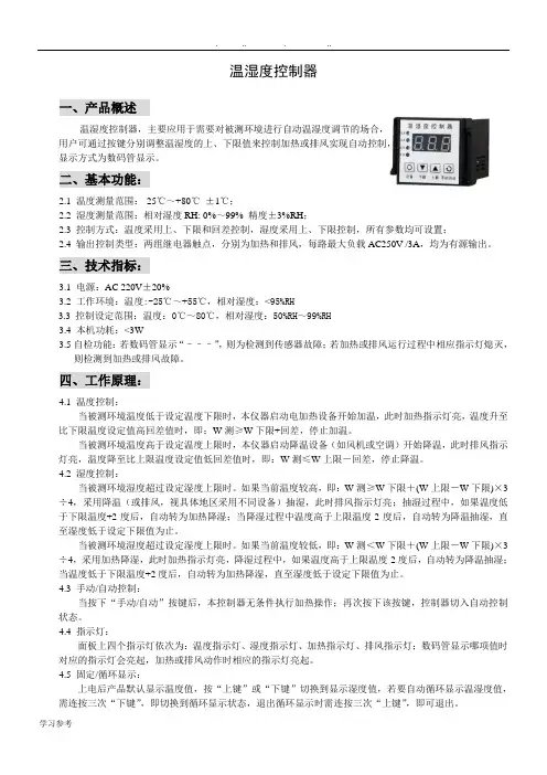
温湿度控制器一、产品概述温湿度控制器,主要应用于需要对被测环境进行自动温湿度调节的场合,用户可通过按键分别调整温湿度的上、下限值来控制加热或排风实现自动控制,显示方式为数码管显示。
二、基本功能:2.1 温度测量范围:-25℃~+80℃±1℃;2.2 湿度测量范围:相对湿度RH: 0%~99% 精度±3%RH;2.3 控制方式:温度采用上、下限和回差控制,湿度采用上、下限控制,所有参数均可设置;2.4 输出控制类型:两组继电器触点,分别为加热和排风,每路最大负载AC250V /3A,均为有源输出。
三、技术指标:3.1电源:AC 220V±20%3.2 工作环境:温度:-25℃~+55℃,相对湿度:<95%RH3.3控制设定范围:温度:0℃~80℃,相对湿度:50%RH~99%RH3.4 本机功耗:<3W3.5自检功能:若数码管显示“–––”,则为检测到传感器故障;若加热或排风运行过程中相应指示灯熄灭,则检测到加热或排风故障。
四、工作原理:4.1 温度控制:当被测环境温度低于设定温度下限时,本仪器启动电加热设备开始加温,此时加热指示灯亮,温度升至比下限温度设定值高回差值时,即:W测≥W下限+回差,停止加温。
当被测环境温度高于设定温度上限时,本仪器启动降温设备(如风机或空调)开始降温,此时排风指示灯亮,温度降至比上限温度设定值低回差值时,即:W测≤W上限-回差,停止降温。
4.2 湿度控制:当被测环境湿度超过设定湿度上限时。
如果当前温度较高,即:W测≥W下限+(W上限-W下限)×3÷4,采用降温(或排风,视具体地区采用不同设备)抽湿,此时排风指示灯亮;抽湿过程中,如果温度低于下限温度+2度后,自动转为加热降湿;当降湿过程中温度高于上限温度-2度后,自动转为降温抽湿,直至湿度低于设定下限值为止。
当被测环境湿度超过设定湿度上限时。
如果当前温度较低,即:W测<W下限+(W上限-W下限)×3÷4,采用加热降湿,此时加热指示灯亮,降湿过程中,如果温度高于上限温度-2度后,自动转为降温抽湿;当温度低于下限温度+2度后,自动转为加热降湿,直至湿度低于设定下限值为止。
新WTZK-02温度计中文说明书
感谢您使用本厂产品使用前请认真阅读产品使用说明书目录一、用途及外形 (1)二、主要技术参数 (2)三、安装和使用 (2)四、注意事项 (7)一、用途及外形WTZK-02型温度控制器(BWY-02型温度控制器),适用于测量变压器油温或其他场合的液体、气体和蒸汽的温度,并能在被测温度达到和超过设定值时发出接点信号。
本仪表在电力变压器行业中主要用于500KVA 以上的变压器油温的测量和控制。
仪表外形见图1。
二、主要技术参数1.测量范围:0~100℃(或20~120℃)2.指示精确度:1.5级3.开关数量及特性(1)开关数量:2只(2)开关设定精度:±3℃(开关设定与启动的差值)(3)开关差:6±2℃(开关闭合与断开的差值)(4)开关额定负荷:AC220V、3A4.温包尺寸:ф14×1505.温包安装螺丝:外螺纹M27×26.表头安装尺寸:3孔ф6.2 144×210(见图1)7. 开关设置为常开状态,在仪表出厂时标准设定值:第一上限(K) 55℃(闭合)1) 80℃(闭合)第二上限(K2如果用户需调整开关设定值,可打开表盖,请按温度设定程序操作(详见安装和使用4.),完成后按原样合上表盖。
三、安装和使用1. 表头的安装用三颗M6的螺丝,将仪表呈垂直方向固定在仪表安装板上,连接温包之间的毛细管,每隔300mm应有适当的固定,避免毛细管的损坏。
将多余的毛细管部分盘成ф300mm的环圆状,亦有同样的固定。
2.温包的安装温包安装前应先在安装座孔内注满导热油(变压器油),拧松温包上的空心螺栓,使其与安装接头分离。
慢慢将温包插入安装座,任安装座内的导热油溢出,然后拧紧安装接头。
将温包引长管尽可能插入最深,同时在密封垫片以下的引长管上缠绕适当的填料(如生料带),然后将空心螺栓与安装螺丝拧紧,确保安装座内的油与外界完全隔离。
温包插入安装座后应使温包在变压器油的水平线以下,以确保测温的准确性(见图2)。
XMK-2型温度控制器
XMK-2型温度控制器------------------------------------使用说明书功能:1、被控对象的温度测量和显示;2、温度上、下限的设定被控设备的开停控制;3、制冷和制热两种控制模式选择;4、温度传感器故障显示(开路或短路);5、用户可修正显示温度;6、全量程0.1℃分辨率;7、制冷模式时压缩机停机延时3分钟保护;一、功能和操作:1.通电温度显示:控制器通电后显示“---”,约3秒后显示实际温度测量值。
2.参数设定:(1)进入设定状态:为了防止误操作和避免闲人玩弄,必须连按“set(设置)”键三下,才能进入设定状态。
(2)控制器进入设定状态后,首先显示上限设定提示符为“H--”(高,即下限),首次按“▲”健或“▼”键显示上限设定值,再次按“▲”健或“▼”键改变上限设定值;此时可按“▲”健或“▼”键改变设定值,直至符合要求(设定为负值时,负号闪烁);再次按“set(设置)” 显示下限设定提示符为“L--”(低,即下限),设定方法同上;再次按“set(设置)”显示显示修正温度提示符为“C--”,设定方法同上;再次按“set(设置)” 显示显示控制模式提示符为“J--”,首次按“▲”健或“▼”键显示当前控制模式(CC:制冷,HH:制热),按“▲”健选择制冷控制模式,制冷模式指示灯点亮,按“▼”键选择制热控制模式,制热模式指示灯点亮。
(3)当上限设定值≤下限设定值,本控制器自动调正上限设定值=下限设定值+l℃。
(4)退出设定:15秒之内不按任何一个键,控制器自动退出设定状态,并自动保存设定值,显示屏上仍显示温度测量值。
敬告一:修改设定值后必需再按一下“set”键,使设定值得以确认并储存,否则控制器不能按新的设定值进行控制。
敬告二:若设定完后未经延时退出就(断电)关机,新设定值将得不到保存,控制器仍按原设定值运行。
(5)显示屏显示温度=实际温度+温度修正值,一般情况下,修正值设定为0。
士林_温控器操作手册
ɛዚʧࠦEUӻΐeʃ̙ۨόછՓኜAX/AXONӻΐeᜊ᎖ኜSH/SS/SV/SEӻΐe ฆཥ໘ܓછՓኜSD/WTӻΐeᅰЗ္છ׳ᅂዚPHӻΐ
SUNX/ชኜʿཤ࢛ᅺႦዚeପ/ᜊ᎖ኜeCKD/٤Ꮐପۜecognex/ᅂ྅ชኜ(Checker)e Aiphone/ᅂ྅࿁ᑺዚeɧഷ/PLCeɛዚʧࠦeᜊ᎖ኜeУӻ୕
08122K185
微電腦溫度控制器 操作手冊
series series
目錄
1 注意事項...................................................................................................
22
9.2 Level2 (PID 層)
8.2.1
參數“顯示/隱藏”條件 .....................................................
23
8.2.2
參數說明 ......................................................................
14 更改輸入類型 : TC , RTD ................................................................................
40
15 更改輸入類型 : 類比電壓電流信號
15.1 硬體部分 .................................................................................................
BWY(WTYK)-802、803温度控制器说明书中文
感谢您使用本厂产品使用前请认真阅读产品使用说明书目录一、概况 (1)二、工作原理 (5)三、主要技术指标 (5)四、安装及使用 (5)五、注意事项 (10)六、附录Pt100工业铂电阻分度值表 (11)一、概况1、温度控制器根据沈阳变压器研究所制订的JB/T6302《变压器用压力式温度计》标准的命名如下:22、温度控制器根据JB/T9236《工业自动化仪表产品型号编制原则》的要求产品命名如下:2BWY(WTYK)系列温度控制器的成套性和适用性图一 系列温度控制器外形及安装尺寸B W Y (W T Y K )二、工作原理变压器温度控制器(以下简称温控器),主要由弹性元件、毛细管、温包和微动开关组成。
当温包受热时,温包内感温介质受热膨胀所产生的体积增量,通过毛细管传递到弹性元件上,使弹性元件产生一个位移,这个位移经机构放大后指示出被测温度并带动微动开关工作,从而控制冷却系统的投入或退出。
BWY(WTYK)-802A、803A温控器采用复合传感器技术,即仪表温包推动弹性元件的同时,能同步输出Pt100热电阻信号,此信号可远传到数百米以外的控制室,通过XMT数显温控仪同步显示并控制变压器油温。
也可通过数显仪表,将Pt100铂电阻信号转换成与计算机联网的直流标准信号(0~5)V、(1~5)V或(4~20)mA输出。
三、主要技术指标(一)BWY(WTYK)-802、803型1、正常工作条件:(-40~+55)℃2、测量范围:(-20~+80)℃(0~+100)℃(0~+120)℃(0~+150)℃3、指示精确度: 1.5级4、控制性能:①设定范围:全量程可调②设定精确度:±3℃③开关差: 6±2℃④额定功率: AC 250V/3A⑤标准设定值:802:K1=55℃; K2=80℃803:K1=55℃; K2=65℃ K3=80℃5、仪表安装尺寸:详见外形及安装尺寸图(二)BWY(WTYK)-802A、803A型1~5条同上。