CDSK-3100(3200)变电站智能锁控系统技术说明书
CDSK-31003200变电站智能锁控系统技术说明书
CDSK-3100〔3200〕变电站智能锁控系统技术说明书崇道电力科技2012-9-16目录一、概述1.1概述1.2适用围二、系统工作原理2.1根本原理2.2五防操作流程2.2.1预演操作2.2.2实际操作2.3通道门操作流程2.3.1正常权限操作2.3.2临时授权操作三、型号分类3.1CDSK-3110纯五防型变电站智能锁控系统3.2 CDSK-3120纯通道门型变电站智能锁控系统3.3 CDSK-3130带图形模拟型变电站智能锁控系统3.4 CDSK-3140不带图形模拟型变电站智能锁控系统四、闭锁实现方法4.1断路器闭锁实现方式4.1.1遥控操作的闭锁4.1.2就地操作闭锁4.2电动刀闸闭锁实现方法4.2.1刀闸机构箱4.2.2端子箱4.2.3遥控操作4.3线路验电闭锁实现方式4.3.1有源正验电4.3.2有源负验电4.3.3无源负验电五、主要部件介绍5.1智能钥匙5.2多功能适配器5.3简易适配器5.4锁具及附件六、性能指标6.1使用环境6.1.1环境温度6.1.2环境湿度6.1.3电磁干扰强度6.2额定参数6.2.1主机6.2.2模拟屏6.2.3智能钥匙6.2.4智能适配器6.2.5电编码锁6.2.6 编码挂锁6.2.7接地锁6.2.8解锁钥匙七、常见故障处理附录一存贮及保修附录二开箱及检查附录三供货的成套性附录四订货须知附录五五防常识特别提示:本书说明是CDSK-3100单站式变电站智能锁控系统、CDSK-3200集控型变电站智能锁控系统共同的说明书,但书中描述以CDSK-3100单站式变电站智能锁控系统为例。
一、概述1.1概述在发电厂和变电站等环境中存在大量的锁具,大致分为两类:1、五防锁:对一次电气设备进展闭锁、具有五防闭锁功能;2、通道门锁:对重要区域出入通道门、各类设备箱柜门及各类手动设备操作机构进展闭锁。
对第一类锁具,目前常见的是采用微机防误操作闭锁系统对其进展统一操作和管理。
OPEN-3200___SCADA使用手册

OPEN-3200配电网自动化管理系统SCADA使用手册国电南瑞科技股份有限公司二零零六年十一月前言OPEN-3200配网自动化管理系统建立在OPEN-3000支撑平台上,主要子系统包括:实时数据采集和监控(SCADA)、配电自动化DA、调度作业管理、组件化的配网应用软件、增量式的DMS 与GIS数据集成等。
OPEN-3200配电网自动化管理系统是一个信息集成及综合利用系统,对配电工作进行流程化管理,涵盖计划检修、事故抢修指挥等各项日常工作,实现配电日常工作的自动化及无纸化,保证了调度工作的安全及合理性,全面降低调度日常工作强度,提高供电可靠性,充分体现配电网自动化管理系统的规模经济效益。
实时监控子系统(SCADA)是架构在OPEN-3000统一支撑平台上的最基本应用,接收前置子系统(FES)送来的实时数据,实现完整的、高性能的实时数据监控与处理,是DMS其它应用的数据基础。
其主要功能包括:数据处理、数据计算与统计考核、控制和调节、事件和告警处理、拓扑着色、事故追忆(PDR)及反演、人工操作等。
配网调度作业管理是架构在OPEN-3000统一支撑平台与SCADA子系统上的应用子系统,主要实现以下功能:设备检修申请单管理模块、调度计划管理模块(图形开票)、保电计划管理模块(主要为保电单的录入)、调度(日志)运行记事管理模块、调度日报管理模块、调度操作记录管理模块、交接班记录管理模块、事故处理模块、停电通知管理模块、供电可靠率统计模块等。
配电自动化DA主要实现配电网的故障处理,即故障定位、隔离以及恢复功能,实现了在线运行与离线DA模拟功能。
基于CIM/XML的GIS与DMS平滑集成采用可配置的数据校验规则以及拓扑校验规则,并自动形成校验报告;支持GIS地理接线图和线路沿布图到DMS的图形转换,并实现网络模型自动拼接;实时数据和设备投运信息即时发送给GIS系统,GIS与DMS形成完整的闭环流程控制。
本手册为OPEN-3200配电网自动化管理系统SCADA使用人员编写,由于时间仓促,编写中的疏漏和不足之处在所难免,欢迎提出宝贵意见和修改建议。
智能门禁管理系统说明书

一体式/嵌入式门禁管理系统使用说明书目录1.系统简介 ...................................... 错误!未指定书签。
2.功能特点.......................................... 错误!未指定书签。
3、主要技术参数...................................... 错误!未指定书签。
4、系统组成.......................................... 错误!未指定书签。
5、设备连接.......................................... 错误!未指定书签。
6、门禁管理系统软件.................................. 错误!未指定书签。
6.1 软件的安装...................................... 错误!未指定书签。
6.2 人事管理子系统................................... 错误!未指定书签。
6.3 一卡通管理系统.................................. 错误!未指定书签。
6.4 门禁管理子系统.................................. 错误!未指定书签。
7. 调试操作流程...................................... 错误!未指定书签。
8、注意事项.......................................... 错误!未指定书签。
1.系统简介在高科技发展的今天,以铁锁和钥匙为代表的传统房门管理方式已经不能满足要求,而集信息管理、计算机控制、 1 智能(射频)卡技术于一体的智能门禁管理系统引领我们走进新的科技生活。
1 智能(射频)卡上具有先进的数据通信加密并双向验证密码系统,卡片制造时具有唯一的卡片系列号,保证每张卡片都不相同。
智能门禁管理控制系统功能说明

智能门禁管理控制系统功能说明克立司帝控制系统(上海)有限公司Crest Control System(Shanghai) Co., Ltd.目录1.技术解决方案 (3)2.系统说明 (4)3.系统技术说明 (5)3.1外形美观 (5)3.2硬件看门狗 (5)3.3人性化管理 (5)3.4方便使用及管理,无需因为卡片丢失而更换设备 (5)3.5丰富实用的报警模式 (5)3.6强制关门 (5)3.7紧急开门功能 (6)3.8双门互锁 (6)3.9防潜回、防尾随设计 (7)3.10里外校验开门模式 (7)3.11支持多种识别设备 (7)3.12灵活丰富的多时段设置 (7)3.13多种保护电路设计 (7)3.14强大的跨网段功能 (7)4.软件功能简述 (8)克立司帝控制系统(上海)有限公司 21.技术解决方案根据项目技术要求,克立司帝提供一种“分体式智能门禁管理系统”,其以综合布线系统为基础,以计算机网络为桥梁,全面实现对通讯系统、办公自动化系统的综合管理。
系统以非接触式智能卡为出入介质,任何外来人员不能随意开启门锁。
所有门禁管理终端通过网络与电脑连接,所有有效卡及用户权限通过软件下载至门禁管理终端,保证脱机、脱网状态下的人员刷卡正常出入。
由于安全性和高效率管理的需要,分体式智能门禁管理控制系统的设计应遵循下列原则: 实用性整个门禁系统方案在符合客户基本需求的基础上,遵循实用的原则,实现高效的利用率和可操作性。
另外,系统门禁管理终端和管理软件相互配合,达到使用系统的最大优化性,管理人员只需具备电脑初级操作水平,通过简单的培训就能掌握系统的操作要领。
稳定性门禁系统的运用在我们的工作和生活中起着相当重要的作用,且门禁是一个长期不间断运行的系统,所以系统的稳定性显得极其重要。
克立司帝的分体式智能门禁管理控制系统终端设备采用全贴片技术,所有电子器件均选用工业级,软件自主研发,在规划与设计方面遵循功能模块化设计原则,使得程序运行更加高效与稳定。
智能门锁说明指导书

第一章概要电池盖螺电池盖1.1、介绍密码加Mif a r e卡办公室、家用智能安全门锁(其锁面如下图所示)是I C一卡通系统组成部分之一,其使用M if a r e卡能够用在其它一卡通设备上。
本门锁系统功能强大,使用灵活方便,(第二代居民身份证可以设置为开门卡,选配)可实现一卡多门、一门多卡开门方法,并可将门锁设置成常开状态,房门假锁(门没有锁好)时,门锁会自动报警提醒。
密码、开门卡全部由用户自己删除和配制,最大限度地减少安全漏洞。
本系统采用M i f a r e卡,是一种普及型感应卡(如小区停车场等)。
本门锁适适用于现代化办公室、写字楼、高级小区公寓、别墅等。
后把手反锁旋扭锁头盖钥匙按键1.2、关键功效特点:前锁体指示灯前把手●卡片类型:M i f a r e感应卡●电容式触摸按键密码输入●微波方法检测卡片靠近●开锁方法可自行设置:M i f a r e卡和密码可独立开锁/M i f a r e卡和密码同时使用才能开锁●卡片在锁上设定,无需系统软件,最多可设2张管理卡,200张开门卡●密码可自行修改,最多可设一个管理密码,50个开门密码●密码支持乱码输入,最长可输入12位●可设置常开状态●门未锁好会报警●低压报警提醒●电池供电,可外接应急电源1.3、关键技术指标●工作电压: 6.0V(4节5号碱性电池)●静态功耗: <50uA●动态功耗: <200mA●电池寿命: 12个月以上●低电压提醒: 4.8V●读卡距离: <30mm●工作温度: -25℃-70℃●工作湿度: ≤80%●控制板尺寸: 40mmx60mm●按键板尺寸:50mm x90mm1.4、开门方法M i f a r e卡密码办公室、家用门锁系统有以下两种开门模式:⑴、独立式:单独使用M i f a r e卡或密码能够开门。
⑵、组合式:M i f a r e卡和密码同时使用才能够开门。
注:1.本系统门锁出厂初始化后管理密码为12345678,开门模式为独立式。
智能控制器访问和操作指南说明书
85464609161011Operating InstructionsIntelligent ControllerAccess and Operation by Web BrowserBefore operating the unit, read these operating instructions thoroughly and keep them for future reference.Model No. CZ-256ESMC1U1006 Kadoma, Kadoma City, Osaka, JapanCV6233189659CONTENTSCONTENTS1. COMPUTER ENVIRONMENT REQUIREMENTS (1)2. LOG-IN (1)3. SCREEN DISPLAY AND OPERATION (2)3-1. [Each Tenant] Screen (2)3-2. [Each Tenant Details] Screen (5)3-3. [All Units] Screen (5)3-4. Distribution Ratio/Usage: Data Download Screen (6)3-5. Alarm Log Screen (7)3-6. Mail Send Log Screen (9)3-7. Program Timer Screen (10)3-8. Tenant Holiday/Timer Special Day Screen (12)3-9. Prohibit Remote Control Screen (13)3-10. WEB Settings Screen (14)3-10-1. Server details (16)4. SUPPLEMENTARY INFORMATION (18)Note:This equipment has been tested and found to comply with the limits for a Class B digital device, pursuant to part 15 of the FCC Rules. These limits are designed to providereasonable protection against harmful interference in a residential installation. Thisequipment generates, uses and can radiate radio frequency energy and, if not installed andused in accordance with the instructions, may cause harmful interference to radiocommunications. However, there is no guarantee that interference will not occur in aparticular installation. If this equipment does cause harmful interference to radio or televisionreception, which can be determined by turning the equipment off and on, the user isencouraged to try to correct the interference by one or more of the following measures:•Reorient or relocate the receiving antenna.•Increase the separation between the equipment and receiver.•Connect the equipment into an outlet on a circuit different from that to which the receiver is connected.•Consult the dealer or an experienced radio/TV technician for help.FCC Caution: To assure continued compliance, follow the attached installation instructions.Any changes or modifications not expressly approved by the party responsible forcompliance could void the user's authority to operate this equipment.ACCESS AND OPERATION BY WEB BROWSER ACCESS AND OPERATION BY WEB BROWSERAccessing the Intelligent Controller from your computer allows you to monitor/operate air-conditioningequipment using a Web browser.1. COMPUTER ENVIRONMENT REQUIREMENTSIn order to use the web browser of your computer to connect to the Intelligent Controller and monitor/operateair-conditioning equipment, the following environment requirements must be met.Supported browser : I nternet Explorer 6.0 or laterJava applet : S un Microsystems Java Plugin Ver 1.4.2 or laterScreen resolution : 1024 × 768 recommended2. LOG-INTo log in to the Intelligent Controller, enter the following into the address bar of the web browser:h ttp://[Intelligent Controller address]/SACWWW/index_[language code].aspFor example, if the Intelligent Controller address is 192.168.0.2 and you want to connect to the English page, enter:h ttp://192.168.0.2/SACWWW/index_en.aspIf the DNS is used and ID name (device name) of the Intelligent Controller is “WindowsCE0”, enter: http://WindowsCE0/SACWWW/index_en.asp.The language codes are as follows.Enter the user ID and password set for the Intelligent Controller to log in.Shows the site name that was set for Intelligent Controller.Enter the user ID that was set for Intelligent Controller.Enter the password that was set for Intelligent Controller.Click the Login button.3. SCREEN DISPLAY AND OPERATION 3-1. [Each Tenant] ScreenAfter you log in to the Intelligent Controller, or when you use the menu to select [1. Status/Control :1. Each tenant], a screen such as shown below appears. (Screen details may differ depending on the user logged in.)NewbuttonUpdates the screen to the latest information.Menu(The menu may differ depending on the user logged in. The following menu appears when logged in as an administrator.) Lets you select one of the following screens.★Administrator Menu★Special User Menu★General User MenuTenant listShows the indoor unit and tenant structure currently accessed by the Intelligent Controller in a list. Select indoor units by clicking different parts of the list.Clicking on the part highlighted in the screen example above will select the individual indoor unit, while clicking on the tenant name (Tenant001, Tenant002, etc. in the example) will select all indoor units for that tenant. Clicking on the top of the list (Tenant in the example) will select all indoor units of the site.Only the tenants that can be operated by the user permission used to log in (administrator, special, general) are displayed. Icon display areaShows icons for indoor units connected to the Intelligent Controller.Clicking on an icon whose frame is shown in reverse will select that unit. Clicking on a tenant name will select that tenant.Notification columnShows information about the connection status of web browser and Intelligent Controller, etc. Alarm code displayShows the alarm code as a tooltip when the cursor is moved over the icon of the indoor unit for which the alarm is occurring. Site nameThe “Site name” set in the Intelligent Controller appears. ⑧ Remote control windowShows the Remote control window. When this window has been closed, clicking on the indoor unit or making another selection will bring it up again.A Status/Control screen sectionShows the status of the indoor unit and the operation condition. When a control operation is performed, the background color of the respective field changes and the Send button becomes available. Clicking the Send button will send all operation steps performed up to this point to the Intelligent Controller. If you instead click the Cancel button or perform a step such as selecting another indoor unit, operation steps performed up to this point will be canceled.ERemote control windowB Control sectionShows controls for possible operation steps such as start/stopswitching, operation mode selection, temperature selection, fanC Send buttonSends the changes made to theIntelligent Controller.D Cancel buttonCancels the changes made.E CHECK buttonsUsed to check the timer setting and remote control prohibitionsetting status.(See “3-7. Program Timer Screen” and “3-9. Prohibit RemoteControl Screen”.)Clicking the Return button will return the display to theprevious screen.Remote control window for general user3-2. [Each Tenant Details] ScreenWhen you use the menu to select [1. Status/Control : 2. Each tenant details], a screen such as shown below appears. (Screen details may differ depending on the user logged in.) Operation principles for this screen are similar to those of the “3-1. [Each tenant] screen”.3-3. [All Units] ScreenWhen you use the menu to select [1. Status/Control : 5. All units], a screen such as shown below appears.(Screen details may differ depending on the user logged in.) A maximum of 256 indoor units are displayed in1 screen. Operation principles for this screen are similar to those of the “3-1. [Each tenant] screen”.3-4. Distribution Ratio/Usage: Data Download ScreenWhen you use the menu to select [3. Distrib. ratio/Usage : 3. Download] while logged in as an administrator,a screen such as shown below appears.You can download files by selecting them and clicking the “Download” button.A cut-off data file appears for each piece of cut-off data that appears on the Intelligent Controller unit. Beaware, however, that the dates that appear on the Intelligent Controller unit appear as file names on this screen.For example, cut-off data that appears as “01/Apr-30/Apr” on the Intelligent Controller will appear as“20070401-200704301.csv” on this screen.When the following message appears after clicking the “Download” button, select “Open” or “Save”.•“Open” ........ Open the selected CSV file using spreadsheet software.•“Save” ......... Select a folder and save the CSV file.3-5. Alarm Log ScreenWhen you use the menu to select [4. Maintenance/Test Run : 2. Alarm log] while logged in as anadministrator or special user, a screen such as shown below appears.When an indoor unit is selected in the tree section, the previous 14 occurrences are displayed.(Same as the display on the Intelligent Controller.)“I/D alarm log”, “O/D comm. error log”, and “Adaptor alarm log” can be selected from the drop-down list.[O/D comm. error log] logs the history of errors in communication between the outdoor unit and the Intelligent Controller or the communication adaptor.[Adaptor alarm log] logs the history of warnings as determined by the Intelligent Controller or the communication adaptor.(Duplicate adaptor addresses, communication error between the Intelligent Controller and adaptor, etc.)3-6. Mail Send Log ScreenWhen you use the menu to select [4. Maintenance/Test Run : 4. Sent mail log] while logged in as an administrator, a screen such as shown below appears.No.The entry numbers for the sent mail log. With a maximum of 20 (No. 1 to 20) possible entries, the newest entries appear at the top of the list. When the number of entries exceeds 20, entries are deleted starting with the oldest. As up to three mail recipients can be specified, up to three log entries can be recorded for one alarm occurrence.Rslt“OK” appears when an alarm mail is sent properly, and “NG” appears when sending fails.Send T.The date and time the alarm mail was sent (or sending was attempted).ToThe recipient address the alarm mail was sent to. If the address is too long, only part of the address may appear.Unit nameThe name of the indoor unit for which the alarm occurred.Alarm codeThe code for the alarm that occurred.Stat“Occurrence” appears when a notification of an alarm occurrence is sent, and “Restoration” appears when a notification of an alarm restoration is sent.AddressThe address of the indoor unit for which the alarm occurred.The address follows the format, “adaptor number - link number - system (outdoor) number - indoor number”. When a test mail is sent, “TEST_MAIL” appears.⑧3-7. Program Timer ScreenWhen you use the menu to select [6. Auxiliary settings : 3. Program timer] while logged in as anadministrator, or use the “CHECK” button for timer operation in the remote control window, a screen such as shown below appears. (As non-administrator users can only confirm settings and not configure them, the “Cancel” and “Send” buttons only appear when logged in as an administrator.)When the daily timer number is selected in the tree section, the current setting status is displayed.Click the desired setting item, and you can select the setting from the drop-down list as shown below.Drop-down lists are also displayed for the weekly timer in the same way as the daily timer number.Tree section“Cancel”/”Send” buttonsYou can only configure daily timer settings one number (D1, D2, etc.) at a time. If you attempt to switch to D2 settings in the middle of configuring D1 settings, for example, the message “Send for each daily timer.” appears.In such a case, apply or cancel the current settings by clicking the “Send” or “Cancel” button, respectively, before configuring the next daily timer number.For details on the settings, refer to the operation manual for the Intelligent Controller.The “Check RC prohib.” button appears in the previous page when logged in as an administrator or special user. When you click on this button, a screen such as shown below appears.3-8. Tenant Holiday/Timer Special Day ScreenWhen you use the menu to select [6. Auxiliary settings : 4. Ten.Ho/TimerSp.Day] while logged in as an administrator, a screen such as shown below appears.Tree section “Cancel”/”Send” buttons“Copy” buttonYou can only configure tenant holiday/timer special day settings one tenant at a time. If you attempt to switch to Tenant002 settings in the middle of configuring Tenant001 settings, for example, the message “Send for each tenant.” appears.In such a case, apply or cancel the current settings by clicking the “Send” or “Cancel” button, respectively, before configuring the next tenant.To copy changed settings, click the “Send” button and apply the settings before copying.For details on the settings, refer to the operation manual for the Intelligent Controller.3-9. Prohibit Remote Control ScreenWhen you use the menu to select [6. Auxiliary settings : 5. Prohibit R/C] while logged in as an administrator, or click the “CHECK” button for prohibit remote control in the remote control window, a screen such as shown below appears. (As non-administrator users can only confirm settings and not configure them, the “Cancel” and “Send” buttons only appear when logged in as an administrator.)For details on the settings, refer to the operation manual for the Intelligent Controller.3-10. WEB Settings ScreenWhen you use the menu to select [6. Auxiliary settings” : 10. WEB settings] while logged in as an administrator, a screen such as shown below appears.For details on the settings, refer to the operation manual for the Intelligent Controller.Input values have the following restrictions.Setting ItemInput Range Input Character LimitationsSite nameUp to 40 characters One-byte “=” is prohibitedIP address (each block ) Numbers 0 to 255“0.0.0.0” and “255.255.255.255” are prohibitedSubnet mask Default GatewayDNS (Primary, Secondary) WINS (Primary, Secondary) Numbers 0 to 255“0.0.0.0” is prohibitedDevice Name Alphanumeric characters, “–”, and “_” Up to 15 characters First character must be alphabetic character.“-” and “_” are prohibited as ending charactersSender's SMTP Symbols are “@” “.” “_” “:“ onlySender's account “=“ is prohibitedRecipient account 1 to 3Up to 40 alphanumericcharacters and symbolsTo [3.10.1. Server details] screen“Cancel”/”Send” buttonsIf a value that is outside the input range or input limitations is set, the window below appears.If the network settings have been changed when the “Send” button is clicked, the window below appears. Always check there is no problem restarting the Intelligent Controller unit.When “YES” is clicked for submission, the screen changes as shown below, and the Intelligent Controller unit restarts.When a mail test is sent, the window below appears when the mail settings have been changed.In this case, either click the “Send” button to enable the mail setting changes or click the “Cancel” button to disable the changes, and then send the mail test again.If the Intelligent Controller unit is processing (check configuration, cut-off, backup, etc.), this screen cannot be displayed or updated, mail test cannot be sent, and setting change “Send” cannot be performed. If the Intelligent Controller unit is displaying the initial setting screen (main menu 5) or the Settings screen (main menu 6), setting change “Send” cannot be performed. In either case, the following window appears.3-10-1. Server detailsWhen you click the “Server details” button from the [WEB settings] screen, a screen such as shown below appears.For details on the settings, refer to the operation manual for the Intelligent Controller.To [3-10-1-1 Receiving server settings] screenInput values have the following restrictions.Setting Item Input RangeInput Character LimitationsPort number Numbers 0 to 999999 User ID PasswordUp to 50 alphanumeric characters and symbols3-10-1-1. Receiving server settingsWhen you click the “Receiving server settings” button from the [Server details] screen, a screen such as shown below appears.For details on the settings, refer to the operation manual for the Intelligent Controller.Input values have the following restrictions.Setting Item Input RangeInput Character Limitations Recv. server address (POP3) Up to 40 alphanumeric characters and symbolsSymbols are “@” “.” “_” “:” only User ID Password Up to 50 alphanumeric characters and symbolsPort number Numbers 0 to 999999SUPPLEMENTARY INFORMATION4. SUPPLEMENTARY INFORMATION■ When connecting the Intelligent Controller via Internet, consider implementing network security measures, such as a firewall.■ Error MessagesErrorCauseRemedySystem configuration change!(when logged in with Administrator privileges)The system configuration of the Intelligent Controller has changed. This is a warning message. Wait a moment and resume operation.Intelligent Controller is nowprocessing, please wait. Please try later.The Intelligent Controller is applying settings. Access from the Web is heavy.If configuring settings with the Intelligent Controller, switch to a non-settings screen (such as screen 1-n).Wait a moment and resume operation.Communication errorThe Intelligent Controller was turned off whileconnected, or a cable was unplugged or the network failure.Try the operation again.Verify that the Intelligent Controller is turned on, and that the network wiring connections are correct.Invalid user IDThe entered user ID is different from the user ID registered on the Intelligent Controller.Verify the user ID that was registered to the Intelligent Controller.Wrong passwordThe entered password is different from thepassword registered on the Intelligent Controller.Verify the password that wasregistered to the Intelligent Controller.All Stop!All units were forced to stop.Do not operate until unit operation resumes.The external all stop input is switched on for the Intelligent Controller unit.When the external all stop input is changed to OFF, the messagedisappears. After changing to OFF, wait for the message to disappear.DC1011-11111 Printed in Japan。
DS3100通用平台系统操作手册

DS3100通用平台系统操作手册负责单位:配网自动化事业部协作单位:作者:金松茂批准:签收人:修改情况记录:国电南京自动化股份有限公司目录令号C(03) 01软件简介 (1)2 运行环境 (1)2.1 硬件 (1)2.2 支持软件 (1)3 用户界面 (1)3.1 桌面 (1)3.1.1主菜单 (1)3.1.2工具栏 (2)3.1.3节点服务器树形窗口 (2)3.1.4主窗体 (2)3.1.5节点/进程配置信息 (2)3.1.6调试进程窗口 (3)3.1.7信息分类窗口 (3)3.2 控制条 (3)4 使用说明 (3)4.1 安装和初始化 (3)4.1.1 DS3100初始化说明 (3)4.1.2 SYBASE初始化说明 (4)4.2 出错和恢复 (4)4.2.1 调试信息出错信息及含义:” (4)5 运行说明 (4)5.1 运行表 (4)5.2 运行步骤 (4)6 操作命令一览表 (5)6.1 查询统计模块操作命令 (5)7 用户操作举例 (5)1软件简介随着调度自动化在电力系统的成功应用和配电自动化的小范围试点应用,越来越多的用户对配电自动化系统提出了调度功能,即配调一体化。
调度自动化系统和配电自动化系统有诸多相似之处,他们对实时平台的要求是基本一致的,因此开发DS3100通用平台不仅可以满足调度自动化系统和配电自动化系统,还要满足配调一体化系统的实时需求,实现实时平台的统一,减少实时平台的重复开发。
随着配网自动化系统的自主开发和研制,为目前DS3210、DS3220和DS3300系统提供统一的跨平台实时平台,为配网自动化系统的发展提供基础;并顺应市场的发展,可以为调度自动化系统和配调一体化系统提供一致的跨平台实时平台。
2 运行环境2.1 硬件2.2 支持软件a. 操作系统: WINDOWS 2000;b.编程语言: VC++6.0;c.数据库: Sybase;d.其他软件: sp2;3 用户界面3.1 桌面信息调试用户界面如图:界面可划分为五部分:3.1.1主菜单暂时没有用。
电力安全智能锁控系统说明书
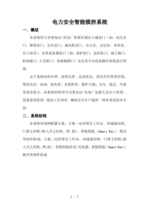
电力安全智能锁控系统一.概述本系统用于对变电站/发电厂重要区域出入通道门(如:高压室门、继保室门、安具室门、通讯机房门、办公室、会议室、资料室、员工宿舍)、各类设备箱柜门(如:保护柜门、监控柜门、端子箱门、机构箱门、汇控柜门、构架爬梯门)及各类手动设备操作机构进行管理。
由于系统结构合理、流程完善、品质优良,使其具有管理全面;使用灵活、高效;投资省、安装简单、维护方便;安全、稳定、可靠等诸多优点。
该系统的使用可为变电站/发电厂加强人员出入管理、设备使用管理,提高工作效率,确保安全生产提供一种有效的技术手段。
二.系统结构本系统有两种配置方案:方案一由管理员工作站、局域通讯网、门禁主控机(嵌入式主控机、PC机)、智能钥匙(Smart Key)、锁具等部件组成;方案二由管理员工作站、局域通讯网、门禁主控机(嵌入式主控机、PC机)、智能钥匙传送/充电器、智能钥匙(Smart Key)、锁具等部件组成系统结构框图一系统结构框图二三.系统特点与传统意义上的门禁系统相比,本系统具有以下特点:1.管理范围广,可以对设备区、办公区、生活区内多种门及各类手动设备操作机构进行管理;2.主控机门禁管理软件设有严格的权限管理功能,使用安全、可靠;在一次任务中,只能对圈定范围内的锁具进行解锁,可以避免走错位置(设备间隔) ;3.操作流程完善、高效,可十秒内完成圈定和授权工作,得到最高权限授权可以打开站内所有的锁具,可大大提高工作效率;4.嵌入式主控机内置工控机、液晶触摸屏、指纹识别器、RFID读卡器、钥匙存放仓、传送/充电器等系统部件,体积小、集成度高;壁挂式结构设计,不占用桌面空间,便于布置;5.智能钥匙体积小,方便操作和携带;功耗低,一次充电可连续开锁3000次以上。
6.无需铺设电缆线,施工简单、成本低,只需要将锁具安装到指定位置,再将对应数据写入软件数据库即可;7.维护方便,不存在线路维护问题,也不会发生通讯故障;8.锁具可靠性高,户外锁锁芯防雨水、防沙尘等级可达IP68级;使用寿命长,不加油可使用十年以上。
- 1、下载文档前请自行甄别文档内容的完整性,平台不提供额外的编辑、内容补充、找答案等附加服务。
- 2、"仅部分预览"的文档,不可在线预览部分如存在完整性等问题,可反馈申请退款(可完整预览的文档不适用该条件!)。
- 3、如文档侵犯您的权益,请联系客服反馈,我们会尽快为您处理(人工客服工作时间:9:00-18:30)。
CDSK-3100(3200)变电站智能锁控系统技术说明书江苏崇道电力科技有限公司2012-9-16目录一、概述1.1概述1.2适用范围二、系统工作原理2.1基本原理2.2五防操作流程2.2.1预演操作2.2.2实际操作2.3通道门操作流程2.3.1正常权限操作2.3.2临时授权操作三、型号分类3.1CDSK-3110纯五防型变电站智能锁控系统3.2 CDSK-3120纯通道门型变电站智能锁控系统3.3 CDSK-3130带图形模拟型变电站智能锁控系统3.4 CDSK-3140不带图形模拟型变电站智能锁控系统四、闭锁实现方法4.1断路器闭锁实现方式4.1.1遥控操作的闭锁4.1.2就地操作闭锁4.2电动刀闸闭锁实现方法4.2.1刀闸机构箱4.2.2端子箱4.2.3遥控操作4.3线路验电闭锁实现方式4.3.1有源正验电4.3.2有源负验电4.3.3无源负验电五、主要部件介绍5.1智能钥匙5.2多功能适配器5.3简易适配器5.4锁具及附件六、性能指标6.1使用环境6.1.1环境温度6.1.2环境湿度6.1.3电磁干扰强度6.2额定参数6.2.1主机6.2.2模拟屏6.2.3智能钥匙6.2.4智能适配器6.2.5电编码锁6.2.6 编码挂锁6.2.7接地锁6.2.8解锁钥匙七、常见故障处理附录一存贮及保修附录二开箱及检查附录三供货的成套性附录四订货须知附录五五防常识特别提示:本书说明是CDSK-3100单站式变电站智能锁控系统、CDSK-3200集控型变电站智能锁控系统共同的说明书,但书中描述以CDSK-3100单站式变电站智能锁控系统为例。
一、概述1.1概述在发电厂和变电站等环境中存在大量的锁具,大致分为两类:1、五防锁:对一次电气设备进行闭锁、具有五防闭锁功能;2、通道门锁:对重要区域出入通道门、各类设备箱柜门及各类手动设备操作机构进行闭锁。
对第一类锁具,目前常见的是采用微机防误操作闭锁系统对其进行统一操作和管理。
而对通道门锁,多是采用一把钥匙开一把锁的原始模式操作。
市场上还没有对五防锁和通道门锁进行统一操作和管理的产品。
CDSK-3100(3200)变电站智能锁控系统是目前唯一将两类锁具集成在一个平台上进行统一管理的系统,率先填补了这一领域的空白,具备如下特点:1、锁具管理全覆盖,即具备五防闭锁功能,又可对通道门锁进行管理。
2、对通道门锁采用权限管理模式,用户登陆钥匙后可在权限范围内自由操作,并可对操作过程进行记录;用户无操作权限则不能操作。
3、多功能适配器支持同钥匙的GPRS无线通讯功能,可以实现操作过程中后台显示设备状态和现场操作设备状态的实时同步变位。
4、通讯适配器具有钥匙管理机功能,可对解锁钥匙和跳步钥匙进行管理。
5、电脑钥匙采用手机式设计,外形美观、制作精美,有防水设计,可在水中进行操作。
6、采用统一的磁编码锁芯,户外锁芯防水防尘防腐蚀,IP68防护等级,使用寿命10年以上。
7、磁编码锁芯可靠性高,能有效防止技术开锁。
1.2适用范围本系统适用于所有电压等级的发电厂、变电站以及涉及电力、石油、石化的厂矿及企业的五防及通道门管理。
二、系统工作原理2.1基本原理系统主要包括三个部分:变电站智能锁控系统软件,适配器(包括多功能适配器和简易适配器)和智能钥匙,安装有FRID编码片和磁编码锁芯的各类锁具。
图形软件将五防锁和通道门锁置于统一的平台上,采用两种完全不同的管理模式。
对五防锁,必须先模拟开票然后才能操作;对通道门锁,则采用权限管理模式,在系统和钥匙中预先设置各个用户的开锁范围、时段等权限。
用户操作前必须登录钥匙,然后才能在权限内自由操作,不登录或超出权限则无法进行任何操作。
2.2五防操作流程必须严格按照先“模拟预演”后“实际操作”的模式进行操作:2.2.1预演操作CDSK-3100变电站智能锁控系统事先将变电站的电气防误操作接线图(简称一次接线图)和各种运行方式的操作运行规程(即所有开关、刀闸、网门等设备的正确操作方式)保存在防误系统软件中,当运行操作人员接受调度令并在一次主接线图上进行模拟操作时,系统会根据当前实时的运行状态检验其模拟操作步骤是否符合五防规则:若操作违背了五防规则,系统将提示正确的操作步骤及有关的操作元件名称和编号。
若符合五防规则,系统将确认你当时的操作步骤,并自动将该步骤记录在当前的操作票上。
整个操作预演过程基于引入的五防操作规则和全站所有设备的实时状态,系统能有效地防止操作票中各种误操作项的出现,确保了操作票的正确性。
2.3.2实际操作现场实际操作有三类:上位机操作、手动电脑钥匙操作和提示性操作。
➢上位机操作:是指需要在监控机上进行的后台遥控操作。
该操作通过监控机与防误主站系统通信的方式,获取操作许可后对现场设备实施遥控操作。
➢手动电脑钥匙操作:运行人员使用电脑钥匙按操作票项的顺序打开操作机构上的编码锁后进行设备操作。
➢提示性操作:不需要进行实际解锁操作的一些二次操作(拉/合保险、确认刀闸在合/分位置、确认已操作等)。
整个实际操作过程均在CDSK-3100变电站智能锁控系统的严格控制下,强制操作人员按照“基本防误闭锁逻辑”和“操作票步骤闭锁逻辑”进行操作。
从而能够达到全方位的防误闭锁操作。
2.3通道门操作流程通道门的操作即可同五防操作同步进行,也可以单独进行。
分为正常权限操作和临时授权任务操作。
2.3.1正常权限操作在系统软件和智能钥匙中都预置有用户的开锁范围和时段权限,用户登录钥匙后在此权限范围内操作称为正常权限操作。
用户的权限配置分为开锁范围权限和开锁时段权限,开锁范围权限即按区域配置,也可细化到具体锁具;开锁时段权限是按每星期的具体时段配置。
2.3.2临时授权操作系统支持对用户的开锁权限临时进行变更,临时授权既可以扩大用户的开锁权限也可以缩小开锁权限,只有具备临时授权权限的管理员才能对其他用户进行临时授权。
对于习惯于模拟后操作的用户,系统将其模拟后传送给钥匙的开锁范围视为一种特殊的临时授权。
这种模拟包括跟五防模拟同时进行的通道门模拟,也包括单独的通道门模拟。
临时授权有失效条件,对于跟五防操作票一起进行的临时授权,当五防票执行完毕后,临时授权即同时失效;对于单独的通道门临时授权,失效条件可以是时段、操作次数等。
当临时授权的失效条件发生后,用户的权限恢复到正常权限。
三、型号分类变电站智能锁控系统分为CDSK-3100单站型和CDSK-3200集控型两种基本型号,根据变电站的锁具。
本书主要以单站型为例做介绍。
3.1 CDSK-3110型图3-1 CDSK-3110型变电站智能锁控系统组成图CDSK-3110型变电站智能锁控系统同于一般的变电站微机防误操作闭锁系统,它的硬件配置包括:工业级PC机、大屏幕显示器、激光打印机、多功能适配器、智能钥匙、根据实际需要选配的模拟盘、锁具和附件等。
系统软件配置包括:五防专家系统、操作票专家系统、图形编绘系统、通讯接口软件。
系统具备一般五防系统的功能:1、PC机大屏幕显示器显示变电站一次主接线图,模拟采用鼠标模拟。
2、操作票专家系统图形开票手工开票调用票开票3、通过与后台监控联络,可实现虚、实遥信等数据的信息共享。
4、强制性五防闭锁,电脑钥匙按操作票顺序解锁。
本系统突出于一般五防系统的功能:1、钥匙管理机功能:多功能适配器集成了钥匙管理机的功能,支持指纹登录和IC 登录。
2、钥匙的实时通讯功能:钥匙内置移动GPRS模块,能将现场操作后的设备状态实时传送给后台,保持现场设备状态和后台状态的实时一致。
3、两个监控通讯功能:系统支持同时跟两个监控通讯的功能,适应于同一变电站有2套不同厂家的监控系统的情况。
4、电气锁的验电功能:电气锁具备多种验电功能,跟智能钥匙配合,能检验开关的分合状态。
5、可扩展通道门功能:系统可扩展通道门闭锁功能,实现变电站锁具管理的全覆盖。
3.2 CDSK-3120型图3-2 CDSK-3120型变电站智能锁控系统组成图CDSK-3120型变电站智能锁控系统仅管理变电站的通道门锁,它的硬件配置包括:工控主机(或者工业级PC机、大屏幕显示器)、简易适配器、智能钥匙、各类锁具、锁芯和附件等。
系统软件配置包括:变电站综合授权系统系统主要功能:1、权限管理功能:2、临时授权功能:3、操作统计功能:4、一键登录功能:3.3 CDSK-3130型图3-3 CDSK-3130型变电站智能锁控系统组成图CDSK-3130型变电站智能锁控系统管理变电站的所有锁具,包括五防锁和通道门锁,具备五防闭锁功能。
它的硬件配置包括:工业级PC机、大屏幕显示器、激光打印机、多功能适配器、智能钥匙、各类锁具、锁芯和附件等。
系统软件配置包括:五防专家系统、操作票专家系统、通讯接口软件、锁控综合授权系统。
系统主要功能:3.4 CDSK-3140型图3-4 CDSK-3140型变电站智能锁控系统组成图CDSK-3140型变电站智能锁控系统管理变电站的所有锁具,包括五防锁和通道门锁,具备五防闭锁功能。
它的硬件配置包括:工业级PC机、大屏幕显示器、激光打印机、多功能适配器、智能钥匙、各类锁具、锁芯和附件等。
系统软件配置包括:五防专家系统、操作票专家系统、通讯接口软件、锁控综合授权系统。
系统功能:除通道门模拟功能外,其他均同于CDSK-3130型变电站智能锁控系统。
四、闭锁实现方式五防锁闭锁的主要是一次设备,包括断路器、电动刀闸、隔离刀闸、接地刀闸(临时接地线)、网门等,其中断路器、电动刀闸一般采用电编码锁方式闭锁,隔离刀闸、接地刀闸(临时接地线)、网门采用机械挂锁与附件配合的方式闭锁。
线路侧验电采用加装验电器方式闭锁。
通道门锁的种类和形式繁多,有整体换锁和更换锁芯两种解决方案。
4.1断路器闭锁实现方法变电站中的断路器有两种操作方式,遥控操作和就地操作。
智能锁控系统对这两种操作方式采用不同的闭锁方式实现闭锁。
4.1.1遥控操作的闭锁智能锁控系统针对遥控操作通常采用的方式是软件闭锁:通过和监控系统通讯,相互配合,完成防止误拉、合断路器。
其实现过程是:锁控系统在进入开票状态后,要向监控系统发一报文,监控系统在收到这一报文后,要封锁所有的遥控命令。
在操作票单步执行过程中,当前操作如果是遥控操作,应由锁控系统向监控系统发一报文,告知当前要进行遥控操作的设备点号,监控系统收到这一点号后,解除相应设备的遥控封锁,可对该设备(而且只能对该设备)进行遥控操作;当遥控完成后,由监控系统告知锁控系统遥信变位,锁控系统收到遥信变位即认为当前遥控操作已完成,可进行下一步操作,同时监控系统封锁对该设备的再次遥控操作。
如此循环直至所有操作完成。
软件闭锁方式在断路器的操作回路和控制回路中不增加其它任何辅助节点。
4.1.2就地操作闭锁采用电编码锁实施闭锁。