ZigBee无线模块说明书
顺舟科技 SZ05 系列 ZigBee 嵌入式无线数传模块 说明书
SZ05 系列嵌入式无线数传模块用户手册
SZ05 系列 ZigBee 嵌入式无线数传模块 用户手册
-1-
SZ05 系列嵌入式无线数传模块用户手册
文档修订记录 版本 V1.0
V1.1 V1.2
变化状态 新增 修改
修改及正式发布
日期 2011-07-20 2011-07-31 2011-08-08
-4-
SZ05 系列嵌入式无线数传模块用户手册
1.2 性能特点
主要功能描述:有 RS232、485、TTL 接口与无线 Z-BEE 的相互转换,通过无线 ZIGBEE 进行组网通信;
ZigBee无线模块说明书

Coordinator 或Router 不能大于模块间组网的最大距离。
-5-
演示与测试 当通过调试软件向网络中其中任意一个模块的串口发送数据时,你可
以在网络中其它所有模块的串口上接收到相同的数据,这表明ZigBee 网络 运行正常。 注意事项
基于ZigBee 的原因,每次向串口发送的数据长度不要多于70 个字节。 过快地通过串口向模块发送数据可能会造成数据丢失。 Zigbee网络
ZigBee 无线模块使用说明书 一、 概述
该模块是一款基于 ZigBee 标准协议的微功率无线数传模块。基于该模块 开发的无线产品可用于各种智能仪表;家庭智能控制装置;安防、报警;酒店、 机房设备无线监控,门禁系统,人员定位;交通、路灯控制;物流、有源 RFID、 POS 系统,无线手持终端;工业遥控、遥测,自动化数据采集;无线传感网络 等。 Zigbee微功率无线数传模块特点 开放频段,无需申请频点,载频频率2.4GHz; 高抗干扰能力和低误码率,基于O-QPSK 的调制方式,采用高效前向纠
2
P00
ADC 输入第 0 通道,和通用 Pin19
输入输出口复用。
3
P01
ADC 输入第 1 通道,和通用 Pin18
输入输出口复用。
4
P02
ADC 输入第 2 通道串口支持 Pin17
UART 和 SPI 两种模式
5
P03
ADC 输入第 3 通道串口支持 Pin16
-2-
UART 和 SPI 两种模式
调制方式 工作频率 发射功率 传输距离 接收灵敏度 发射电流
O-QPSK 2.40~2.4835GHz
≧18dBm 700m -94dBm
≦166mA
zigbee模块使用手册

2.4G无线模块WLT2408NZ产品数据手册编号:DSWLT01003 更新日期:2012/04/26 版本:V1.03产品概述WLT2408NZ模块是广州晓网电子出品的WLT系列ZigBee数据传输模块,具备最大8dBm 输出功率,视距传输距离可达500米(@5dbi天线),工作频段2.380GHz~2.500Ghz,除标准ZigBee的16个通道外,还有9个扩展频段,可以有效避开WIFI、蓝牙等其他2.4G信号干扰。
广州晓网电子为WLT2408NZ用户提供mesh对等无线路由协议,无组网延时,采用时间空间权值均衡原则,路由时间短,通讯稳定可靠。
基本参数产品图片输出功率:供电电压:天线接口:数字接口:视距传输距离:功耗:休眠电流工作温度:存储温度:尺寸:-50~+8dBm1.9~3.3VSMA,U.FLUART,GPIO,AD500米@5dbi天线发送峰值电流46.3mA,接收时36.4mA <1uA-40℃至+85℃-40℃至+105℃16×23mm公司简介广州晓网电子科技有限公司是一家专门从事无线通讯方案设计、生产及服务的公司,公司拥有一流的设计团队,运用先进的工作方法,集合无线设计经验,公司拥有业界实用的各种模块,也为客户提供客制化服务。
订货信息WLT2408NZ-S SMA形式天线接头WLT2408NZ-U U.FL形式天线接头WLT2408NZ SDK 无线模块评估板套件,包含两个评估板,搭载的模块为WLT2408NZ-S。
数据手册版权声明本文档提供有关晓网电子产品的信息,并未授予任何知识产权的许可,并未以明示或暗示,或以禁止发言或其它方式授予任何知识产权许可,任何单位和个人未经版权所有者授权不得在任何形式的出版物中摘抄本手册内容。
产品命名规则图1-1 产品命名规则例如:WLT2408NZ-S表示晓网电子模块类的产品,频段为2.4GHz,理论输出功率为﹢8dBm(实际输出为﹢7.7dBm),超小封装,调制方式为ZigBee,外置SMA头的模块。
BestU eNet -ZBP113 ZigBee 无线传感网络模块快速入门指南说明书

eNet-ZB ZigBee Module Quick Start GuideBestU eNet-ZBP113 Module-Networking Firmware VersioneNet-ZBP113 Quick Start GuideV1.0 – August 16,2014BestU/enZigBee Wireless sensor network moduleCopyright Statement:●Unless otherwise noted, the eNet-ZB Serials includes but not limit to eNet-ZBP113,eNet-ZBP111, eNet-ZBP211, eNet-ZBP213.●eNet、eNet-ZB Serials ZigBee wireless module and its related Intellectual Propertyowned by Shenzhen BestU Intelligent Technology Co.,Ltd.●Without the permission of Shenzhen BestU Intelligent Technology Co.,Ltd ,No one canmodify, distribute or copy any part of this document.Legal Disclaimer:●The source code, software, documents in company with eDuino UNO, Shenzhen BestUIntelligent Technology Co.,Ltd does not provide any guarantee; Not matter specific,connotative , including but not limited to specific purpose, all the risk should beundertook by end user; If coming out bug in the program, end user undertakes the allthe necessary fee of service, modification, amends.Version Updated:Version Updated Date Description1.0 2014-08-16 ReleasedZigBee Wireless sensor network moduleCatalogue1Overview (3)2Development Kit s (4)2.1 eDuino UNO Wireless Kit (4)2.2 Simple Wireless Kit (5)3Preparation (6)3.1 CP2102 driver Installation (6)3.2 Configuration Software Installation (7)3.3 Hardware Installation (8)3.3.1 eDuino UNO Wireless Kit (8)3.3.2 Simple Wireless Kit (10)3.3.1 Parameter Configuration (12)4Network Establishing (18)4.1 Coordinator settings (18)4.2 Router settings (19)4.3 Joining Network (20)4.4 Network Communication Test (21)5Contact Us (22)ZigBee Wireless sensor network module1OverviewThis document gives a description on how to get started with the eNet-ZBP113 development kits. This document provides a step by step guide to the installation procedure of the software and the hardware.If you buy only the eNet-ZBP113 module, the eNet-ZBP113 User Manual will be helpful when you get started with the module.Chapter 5 shows how to configure the module. Chapter 6 shows how to implement the data transmission between modules. Chapter 7 shows how to establish a network.ZigBee Wireless sensor network module2 Development Kit sThere are two available development kits for eNet-ZBP113, eDuino UNO wireless kit and Simple Wireless kit.2.1 eDuino UNO Wireless KiteNet-ZBP113 ModuleeDuino UNOeDuino UNO kitWhat ’s included in the eDuino UNO kit:Figure 2-1 eDuino UNO KitZigBee Wireless sensor network module2.2 Simple Wireless KiteNet-Test-AeNet-ZBP113 Module Simple Wireless kitWhat’s included in the Simple Wireless kit:Figure 2-2 Simple Wireless KitZigBee Wireless sensor network module3Preparation3.1CP2102 driver InstallationThe first time you connect the development kits to PC, the CP2102 driver need to be installed. Please download the driver from/Support%20Documents/Software/CP210x_VCP_Windows.zipZigBee Wireless sensor network module3.2Configuration Software InstallationBefore you install the configuration software for eNet-ZBP113, you first need to install the Microsoft .Net Framework if your PC has never installed one. The version, v4.0.30319 or later version is OK. Microsoft .Net Framework 4.5 can be downloaded from/en-us/download/details.aspx?id=30653Please download the configuration software from/uploads/soft/Document/ZigBee%20Module%20Config%20Tool.rarZigBee Wireless sensor network module3.3 Hardware Installation 3.3.1eDuino UNO Wireless Kit1) Install the antenna.2) Connect the eNet-ZBP113 module.Caution: Please take care to connect the module in the right way! See the next picture for more information.3) In order to make the USB-UART connect to eNet-ZBP113 module, jumpers should be fittedas follow figure shown.Figure 3-1 eNet-ZBP113 ModuleFigure 3-2 eDuino UNO KitZigBee Wireless sensor network module4)Plug Micro USB cable into PC and power the board.5)Check the available interface (COM) in Device Manager Window.Figure 3-3 Available Interface (COM)6)The kits start to work.Figure 3-4 eDuino UNO KitZigBee Wireless sensor network module3.3.2Simple Wireless Kit1)Install the antenna.Figure 3-5 eNet-ZBP113 Module2)Connect the eNet-ZBP113 module.Caution: Please take care to connect the module in the right way! See the next picture for more information.Figure 3-6 Simple Wireless Kit3)Connect the kit to PC with Micro USB cable and power the board.4)Check the available interface (COM) in Device Manager window.ZigBee Wireless sensor network moduleFigure 3-7 Available Interface (COM)7)The kits start to work.Figure 3-8 Simple Wireless KitZigBee Wireless sensor network module3.3.1Parameter ConfigurationThis section shows how to quickly configure module parameters with ZigBee Config Tool, a convenience, easy-to-use PC Software.1)Connect the module to PC through USB-UART.Figure 3-9 Connect the ModuleZigBee Wireless sensor network module2)Get the parameters from the Module.Click on the Get Para to get the current parameters of the module.Figure 3-10 Get the parametersZigBee Wireless sensor network module3)Set the network parameters.Set the PANID or change the Point type. Click on Setting button to finish the setting.Figure 3-11 Set the network parametersZigBee Wireless sensor network module4)Set the Radio parameters.Set the channel or TX Power and click on Setting to finish the setting.Figure 3-12 Set the Radio parametersZigBee Wireless sensor network module5)Set the UART parameters.Set the Baud Rate and click the Setting to finish the Setting.Figure 3-13 Set the UART parametersZigBee Wireless sensor network module6)Restart the module.Click the Restart to make the module work with the parameters set by steps before.Figure 3-14 Restart module7)Connect the module. The parameters have been set and shown by click Get Para.ZigBee Wireless sensor network module4Network EstablishingeNet-ZBP113 can act as Coordinator and Router. A ZigBee Network contain one Coordinator and one or more Router. All the nodes in a same network share the same PANID. The default settings of eNet-ZBP113 shown in Appendix I Default Settings of eNet-ZBP113 User Manual.Please note that more than one eNet-ZBP113 need for establish network.4.1Coordinator settingsHere is an example that shows how to configure a module as a Coordinator.Figure 4-1 Coordinator SettingsZigBee Wireless sensor network module4.2Router settingsHere is an example that shows how to configure a module as a Router.Figure 4-2 Router SettingsZigBee Wireless sensor network module4.3Joining NetworkPower the Coordinator before the Router. P0_6 of both modules will output a 1Hz pulse to indicate network establishing complete. Check the Short Add of the Router by click on Get para button. If the Short Add isn’t 0xFFFE, the Router has joined the network.Figure 4-3 Router have joined the networkZigBee Wireless sensor network module4.4Network Communication TestWhen the network is available, data can transfer between the Coordinator and Router.Open HyperTerminal on PC. S end strings “hello Router” from Coordinator and the Router received the strings. Both the Coordinator and Router can send or receive data.Figure 4-4 Network Communication TestZigBee Wireless sensor network module5Contact UsTechnical SupportTel:+86-755-22360817/130****2937Email: ******************Sale SupportTel: +86-755-22360817Email: ****************/130****2937About BestUHi, we are BestU, we believe that you will be more happy and better with our products and services.Our technology focused on IoT and open hardware.We own the“Brain”, the microcontroller module for Industry Area, like a brain to manipulate the various branches.We own the “Brick”, providing base IOT modules like WIFI/ZigBee/NFC/BLE etc. to bring down your development threshold, to quickly build your product prototypeWe own the “Low Kit”, providing the lowest hardware for you to evaluate and build your product. Better because of your good, we hope the products and services we have can make you be more excellent!More info please visit /en。
hac-embee-a11n 2.4g 低功耗无线数传模块(zigbee)用户手册说明书
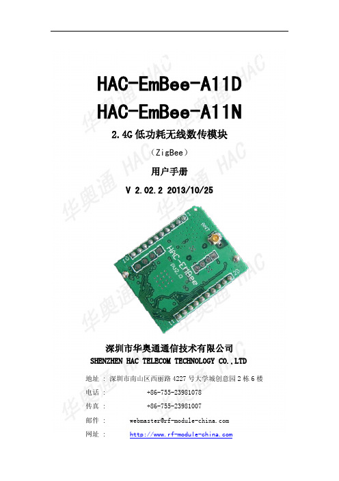
HAC-EmBee-A11D HAC-EmBee-A11N2.4G低功耗无线数传模块(ZigBee)用户手册V 2.02.2 2013/10/25深圳市华奥通通信技术有限公司SHENZHEN HAC TELECOM TECHNOLOGY CO.,LTD地址 : 深圳市南山区西丽路4227号大学城创意园2栋6楼电话 : +86-755-23981078传真 : +86-755-23981007邮件:*****************************网址 : HAC EmBee ZigBee Series 深圳市华奥通通信技术有限公司高性能✧20dbm可视距离2.8km✧7dbm可视距离850m 低功耗✧20dbm发射电流145mA,接收电流38mA,休眠电流3uA✧7dbm发射电流42mA,接收电流29mA,休眠电流3uAMESH网络✧自动组网,自动路由,自动愈合✧点对点,点对多点传输✧最多高达16跳传输 使用简单✧AT命令✧API命令✧API远程AT命令✧透明传输符合标准✧Zigbee 2007 Pro✧A11 Profile高可靠性✧DSSS O-QPSK调制方式✧CSMA-CA 自动退避机制✧重发与应答机制高安全性✧网络层AES加密✧应用层AES加密目录1 EmBee模块 (6)1.1 EmBee模块尺寸及管脚顺序 (6)1.2 模块管脚分布 (7)1.3 模块性能参数 (8)1.3.1 HAC-EmBee-A11N参数 (8)1.3.2 HAC-EmBee-A11D参数 (9)2 EmBee模块操作 (10)2.1 UART串口介绍 (10)2.2 通信协议 (10)2.2.1 透明传输模式 (10)2.2.2 API传输模式 (11)2.3 AT命令模式 (11)2.3.1 进入AT命令模式 (12)2.3.2 发送AT命令 (12)2.3.3 AT命令响应 (12)2.3.4 退出AT命令模式 (13)2.4 回环功能 (13)2.4.1 透传模式的回环 (13)2.4.2 API模式的回环 (13)3 API操作 (14)3.1 API帧格式 (14)3.2 API帧 (15)3.2.1 AT命令帧(立即生效) (15)3.2.2 AT命令帧(不立即生效) (16)3.2.3 AT命令响应帧 (17)3.2.4 传输请求帧 (18)3.2.5 应用层可选的传输请求帧 (19)3.2.6 传输状态帧 (21)3.2.1 数据接收指示帧(AO=0) (22)3.2.2 数据接收指示帧(AO=1) (23)3.2.3 I/O接收指示 (24)3.2.4 节点发现指示 (26)3.2.5 模块状态指示帧 (28)3.2.6 远端AT命令请求帧 (29)3.2.7 远端AT命令响应帧 (30)4 AT命令 (32)4.1 地址命令 (32)4.2 网络命令 (34)4.3 射频参数命令 (36)4.4 串口参数命令 (37)4.5 I/O参数命令 (38)4.6 诊断参数命令 (41)4.7 AT命令参数 (42)4.8 休眠命令 (42)4.9 命令执行 (43)5 数字I/O和模拟I/O (45)5.1 本地I/O (45)5.1.1 AT命令模式下读取本地I/O电平值和采样值 (45)5.1.1 AT命令模式下配置本地I/O (46)5.1.2 API模式下配置本地I/O (47)5.2 远端I/O (47)5.2.1 API模式下配置远端I/O (47)6 EmBee ZigBee网络 (48)6.1 协调器 (48)6.2 路由器 (49)6.3 终端设备 (49)6.3.1 子节点与父节点关系 (50)6.3.2 子节点容量 (50)6.4 子节点工作过程 (51)6.5 父节点工作过程 (51)1EmBee模块1.1EmBee模块尺寸及管脚顺序EmBee模块的外形结构如下:管脚顺序从PIN1开始,逆时针依次至PIN20。
ZigBee无线模块用户手册
ZM516X 系列模块用户手册
FastZigbee 组网固件版
目录
1. 产品简介...................................................................................................................1
产品用户手册
©2013 Guangzhou ZHIYUAN Electronics Stock Co., Ltd. 1
广州致远电子股份有限公司
ZM516X 系列模块用户手册
FastZigbee 组网固件版
1. 产品简介
AW516X 系列 ZigBee 无线模块是广州致远电子股份有限公司基于 NXP JN5168 芯片开 发的低功耗、高性能 ZigBee 模块。工作于标准 ISM 频段(2.4-2.5GHz),完美支持 FastZigBee、 ZLG NET、IEEE802.15.4、JenNet-IP、ZigBee Light Link、ZigBee Smart Energy、RF4CE、 ZigBee-PRO 等协议,可快速应用于工业控制、工业数据采集、农业控制、矿区人员定位、 智能家居,智能遥控器等场合。
广州致远电子股份有限公司
广州致远电子股份有限公司
Hale Waihona Puke 修订历史版本 V1.00
日期 2016-02-18
ZM516X 系列模块用户手册
FastZigbee 组网固件版
原因 创建文档
产品用户手册
©2013 Guangzhou ZHIYUAN Electronics Stock Co., Ltd. i
广州致远电子股份有限公司
FastZigBee FastZigBee FastZigBee FastZigBee FastZigBee FastZigBee
亿佰特TLSR8269 2.4GHz ZigBee多功能SoC无线模块E180-Z6907A使用手册
第一章概述 (3)1.1产品简介 (3)1.2功能特点 (3)1.3设备类型介绍 (4)1.3.1 非休眠终端 (4)1.3.2 休眠终端 (4)1.4 应用场景 (4)第二章规格参数 (5)2.1 极限参数 (5)2.2 工作参数 (5)第三章机械尺寸与引脚定义 (6)第四章工作模式 (7)4.1 传输模式 (7)4.2 配置模式 (8)4.3 模式切换 (8)4.3.1 指令切换 (8)4.3.2 引脚切换 (8)第五章收发方式 (8)5.1数据发送的方式 (8)5.1.1广播模式 (8)5.1.2 组播模式 (9)5.1.3 单播模式 (9)5.2 接收数据的输出方式 (9)5.2.1 透明输出 (9)5.2.2 数据+短地址 (9)5.2.3 数据+长地址 (9)5.2.4 数据+RSSI (9)5.2.5 数据+短地址+RSSI (9)5.2.6 数据+长地址+RSSI (10)第六章应用功能和指令配置 (10)6.1 功能引脚 (10)6.1.1 LINK 详解 (10)6.1.2 WAKE详解 (10)6.1.3 AUX详解 (10)6.1.4 ACK详解 (10)6.1.5 UART_BAUD_RESET详解 (10)6.2 无线远程配置功能 (11)6.3功能参数说明 (11)6.5 HEX指令集 (12)6.5.1 指令规则 (12)6.5.2 读取指令集 (13)6.5.2 配置指令集 (15)6.5.3 网络操作指令集 (16)6.6 HEX 参数说明 (17)6.6.1 系统发送模式 (17)6.6.2 接收数据输出方式 (17)6.6.3网络节点类型 (17)6.6.4网络状态 (17)6.6.5网络 PAN_ID (18)6.6.6网络短地址: (18)6.6.7 MAC 地址 (18)6.6.8父节点网络短地址 (18)6.6.9父节点 MAC 地址 (18)6.6.10网络组号 (18)6.6.11网络信道 (18)6.6.12发送功率 (18)6.6.13串口波特率 (19)6.6.14休眠时间 (19)6.6.15父节点保存时间 (19)6.6.16父节点丢失后网络重连的周期 (19)6.6.17尝试重连的最大次数 (19)6.6.18无线远程配置ID (20)6.6.19用户 gpio 参数 (20)6.6.20用户 pwm 参数 (20)6.6.21用户 adc 参数 (21)6.6.22 配置所有网络参数 (21)6.6.23 读取所有网络参数 (21)第七章快速入门 (22)7.1 快速建立一个ZigBee网络 (22)7.2 快速加入一个ZigBee网络 (25)7.3 ZigBee网络通信测试 (28)7.3.1单播测试 (28)7.3.1.1终端和协调器之间相互以短地址形式单播 (28)7.3.1.2终端和协调器之间相互以长地址形式单播 (29)7.3.2组播测试 (30)7.3.3广播测试 (32)第九章常见问题 (33)9.1 传输距离不理想 (33)9.2 模块易损坏 (33)9.3 误码率太高 (33)关于我们 (34)第一章概述1.1产品简介E180-Z6907A是基于TELINK TLSR8269无线SOC设计生产的一款小体积、低功耗、高可靠性、工作在2.4GHz 频段的ZIGBEE模块,芯片自带高达48Mhz的32位高性能MCU,发射功率最高可达到7dBm。
ZigBee低功耗无线数传模块 HAC-LBee 说明书 V3
HAC-LBee 2.4G低功率无线数传模块 (基于ZigBee协议) V3.X 深 圳 市 华 奥 通 通 信 技 术 有 限 公 司 目 录 一、HAC-LBee低功率无线数传模块特点 (2)二、HAC-LBee低功率无线数传模块的应用 (2)三、HAC-LBee低功率无线数传模块的技术规格 (2)四、HAC-LBee低功率无线数传模块测试开发 (5)五、HAC-LBee低功率无线数传模块的工作模式 (10)六、辅助软件 (30)七、附录 (31)深圳市华奥通通信技术有限公司 地址:深圳市福田区泰然九路海松大厦A座19楼1903区 电话:+86-755-23981076,23981078 传真: +86-755-23981007 邮箱:webmaster@rf-module-china.com 网址:www.rf-module-china.com 一、 HAC-LBee低功率无线数传模块特点HAC-LBee 是一款采用ZigBee协议栈的低功率无线数传模块,它有如下特点: l发射功率100mW(20dBm);接收灵敏度 -105dBm (BER=10-2) l开放频段,无需申请频点,载频频率2.4GHz。
l高抗干扰能力和低误码率 基于QPSK的调制方式,采用高效前向纠错信道编码技术,提高了数据抗突发干扰和随机干扰的能力。
采用直序扩频技术,有效的抗同频窄带干扰。
自带16位CRC校验,能有效检错。
l空中传输速率高达250kbps。
l视距情况下,可靠传输距离可达1000m。
lHAC-LBee提供16个信道,根据环境自动选择可靠信道通信。
lHAC-LBee提供TTL电平/UART接口。
波特率出厂为38400bps,8N1数据格式。
l功耗:接收电流≤50mA,发射电流≤160mA。
l体积小、重量轻。
l采用SOC,外围电路少,可靠性高,故障率低。
l提供PCB板天线,鞭状天线,IPX天线连接座等多种天线连接方式。
ICP DAS ZT-2055 智能zigbee模块用户指南说明书
ZT-2055ZigBee Wireless Module with 8-ch Digital Input and 8-ch Digital Output ModuleQuick Start GuideProduct Website:https:///zt_2055.htmlIntroductionThe ZT-2055 offers 8 isolated channels for digital input and 8 isolated channels for digital output. Either sink-type or source-type digital input can be selected via wire connections. All digital input channels are also able to be used as 16-bit counters. The ZT-2055 supports source-type output with short circuit protection. There are options for configuring power-on and safe digital output values. The ZT-2055 has 16 LED indicators to display the channel status, and has 4 kV ESD protection and 2500 VDC intra-module isolation. Users can easily configure the module address, protocol, checksum, ZB-PID and ZB-channel settings using a combination of rotary and DIP switches.The shipping package contains the following items:ZT‐2055 DIO Device ANT‐124‐05 Quick Start2 Preparing the Device1. Refer the chapter 3. to configure the DIP switch of ZT-2055 I/O device.2. Install the ZT Configuration Utility to configure the ZT-2055 coordinator. CD:\Napdos \ZigBee \ZT_Series \Utility /pub/cd/usbcd/napdos/zigbee/zt_series/utility3. Power Supply: +10 ~ +30 V DC3.1Introduction to the Configuration ParametersA.“Pan ID” parameter is the group identity for a ZigBee network, and must the samefor all devices in the same ZigBee network.“Address/Node ID” parameter is the individed identity of a specific the ZigBeemodule, and must be unique for each device connected the same ZigBee network.B.“RF Channel” parameter indicates the radio frequency channel, and must be set to thesame value as other modules on the same ZigBee network.Channel0x000x01……0x0FFrequency(MHz)24052410 (2480)※RF channels 0x04, 0x09, 0x0E or 0x0F are recommended because they do not overlap with the Wi-Fi frequencies based.802.11b/g802.11b/gChannel 1Channel 62400 000102030405060708090A0B0C0D0E0F 2485MHz MHz802.11b/g Channel (North America)802.15.4 ChannelC. Protocol/Application Mode:When implementing custom programs based on different protocols, the following application modes are recommended in order to ensurecommunicatibleUser Program Protocol DCONModbus RTUModbus TCP ZT-2055 I/O ZT-2550ZT-2570 DCON Transparent TransparentModbus RTUTransparent TransparentModbus Gateway Modbus Gateway Modbus RTU------Modbus Gateway4 Rotation Switch and DIP SwitchThe configuration of ZT-2055 series can be adjusted by using the external rotary switch and the DIP switches. The ZT-2055 device should only be rebooted once the configuration is complete.DIP Switch to the ZT‐2042/ZT‐2043/ZT‐2055/ZT‐2055Protocol Pan ID123456789101112 Address LSB Address MSBChecksum RF Channel Reserved (Node ID)(Node ID)DIP Switch to the ZT‐2055/ZT‐2060Pan IDProtocolAddress LSB Address MSBChecksum RF Channel (Node ID)(Node ID)ZT-2055 - 8-channel DI DAQ module - QuickStart (Dec/2019)ICP DAS USA, Inc. | | 1-310-517-9888 | 24309 Narbonne Ave. Suite 200. Lomita, CA 90717※Once the address of hardware switch is set to 0x00, it mens the address is using software configurations. Refer the more detailed information at Sec. 6.6 of user manual.DIP SwitchNumber Item Status Explain1Address MSB OFF Valid Address (Node ID) from 0x00 to 0x0F ON Valid Address (Node ID) from 0x10 to 0x1F2Protocol OFF DCON ProtocolON Modbus RTUProtocol3Checksum OFF Disabled ON Enabled4ZigBee Pan ID OFF Pan ID = 0x0000 ON Pan ID = 0x00015OFF------ON0x086OFF------ZigBee ON0x04 RF Channel7OFF------ON0x028OFF------ON0x01ZT-2055 - 8-channel DI DAQ module - QuickStart (Dec/2019)ICP DAS USA, Inc. | | 1-310-517-9888 | 24309 Narbonne Ave. Suite 200. Lomita, CA 90717As the ZigBee network is controlled by the ZigBee coordinator, the ZT-2550/ZT-2570 (ZigBee coordinator) must be configured first. Please refert to documents shown below for full details of how to configure these devices.Once configuration of the ZigBee coordinator has been completed. Set the ”Pan ID” and the “RF Channel” values for the ZT-2000 I/O device to the same values as the network, and then reboot the device. The module will automatically start to function on the ZigBee network using the default protocol.※Configuration Utility (Used to configure ZT-2000 I/O device Coordinator)/pub/cd/usbcd/napdos/zigbee/zt_series/utility/ZT-2055 - 8-channel DI DAQ module - QuickStart (Dec/2019)ICP DAS USA, Inc. | | 1-310-517-9888 | 24309 Narbonne Ave. Suite 200. Lomita, CA 90717ZT-2055 - 8-channel DI DAQ module - QuickStart (Dec/2019) ICP DAS USA, Inc. | | 1-310-517-9888 | 24309 Narbonne Ave. Suite 200. Lomita, CA 90717Configurations of ZT‐2550/ZT‐2570Configurations of ZT-2000 I/O DeviceNumber ItemStatus Explain1 Address MSB OFF Address/Node ID is 01(Rotation Switch=1)2 Protocol ON Use Modbus RTU Protocol3 Checksum OFF Disabled4 ZigBee Pan ID OFF Pan ID=0x0000 5ON 0x08 6 ZigBeeON0x04ZigBee RF Channel = 0x0E 7RF ChannelON0x02 8OFF------Once the ZT-2000 I/O device has joined the ZigBee network, the signal quality can be comfirmed by monitoring the status of the ZigBee Net LED indicators. If the LED indicator shows a steady light, communication with the ZT-2000 I/O device has been successfully established for data acquisition and control.ICP DAS also provides the “DCON Utility”, which can be used to simulate DCON/Modbus communication. This software can also be used to verify the device settings and ZigBee I/O functions.※The DCON Utility can be dowmload from:/pub/cd/8000cd/napdos/driver/dcon_utility/Simulate I/O channel operating via using DCON Utilityunch DCON Utility and select the correct COM Port settings to connect theZigBee Coordinator (ZT-2550/ZT-2570).2.Clicking “Search” button will start searching which ZT-2000 I/O device is in thesame ZigBee network.3.If there is any ZT-2000 I/O devices displayed, double clicking the “modulename” will start the I/O channels operated platform.ZT-2055 - 8-channel DI DAQ module - QuickStart (Dec/2019)ICP DAS USA, Inc. | | 1-310-517-9888 | 24309 Narbonne Ave. Suite 200. Lomita, CA 90717ZT-2055 - 8-channel DI DAQ module - QuickStart (Dec/2019)ICP DAS USA, Inc. | | 1-310-517-9888 | 24309 Narbonne Ave. Suite 200. Lomita, CA 907178 Troubleshooting(1)Technical Support.If you have any difficulties using your ZT-2000 series I/O device, please send adescription of the problem to ******************Include the following items in your email:● A description or diagram of the current DIP switch positions.● A copy of the configuration file for the ZT-2000 coordinator. This file can beobtained using the procedure outlined below and should be attached to your email.a.Set the DIP switch of the ZT-255x device to the [ZBSET] position then reboot thedevice. Launch the ZT Configuration Utility and select [Save Log] icon to save the configuration of the ZT-255x as a file.b.After clicking the [Save Log] icon, enter the “File Name” and the “File Path” inthe Windows “Save” dialog box. Once the configuration has been successfullysaved, the following message will be displayed.c.(2)LED Indicator Status:LED Indicator Status IntroductionZigBee Router (Slave)Steady Lit The Signal is StrongBlinking (500 ms)The Signal is AvailableBlinking (1s)The Signal is WeakBlinking (2s)The Signal is Unstable or There is no AvailableThe status of module boardSteady Lit The Power is ON and the Module Initialization is CorrectZigBee PWR Blinking (200ms)Module Initialization Failure(Red LED)Watchdog is Enabled and the status of the I/O channel Blinking (1s)has been changed to the Safe Value. Reset the modulevia the power switch or configuration commands.Steady Unlit The Power is OFFThe status of DI/DO channelsZigBee DI/DO Steady Lit The DI/DO channel is EnabledSteady Unlit The DI/DO channel is Disabled。
zigbee模块设置使用说明
Zigbee简介:Zigbee网络通常由三种节点构成:z协调器(Coordinator):用来创建一个Zigbee网络,并为最初加入网络的节点分配地址,每个Zigbee网络需要且只需要一个Coordinator.z路由器(Router):也称为Zigbee全功能节点,可以转发数据,起到路由的作用,也可以收发数据,当成一个数据节点,还能保持网络,为后加入的节点分配地址.z终端节点(End Device):通常定义为电池供电的低功耗设备,通常只周期性发送数据。
或者通过休眠按键控制节点的休眠或工作。
注意:三种Zigbee节点的P ANID在相同的情况下,可以组网并且互相通讯(上电即组网,不需要人为干预)。
这样可以通过P ANID区分zigbee网络,在同一个区域内,可以同时并存多个zigbee网络,互相不会干扰。
Panid设置见下。
管脚定义:z P1.5:休眠键,输入脚,p1.5拉高时,休眠有效。
模块如果是Cornidator、Router 时此脚无效,只有模块是Enddevice时,此脚才有效,如果不需要休眠功能,则此脚与GND连接。
z p1.7:Set键,输入脚,p1.7拉高时候,设置功能有效,平时模块处于数据收发状态时,此引脚应为低电平,具体设置功能见下节z p2.0 网络连接状态灯,输出脚,模块如果是Router或Enddevice时,此按键表明当前模块是否入网,高电平表明入网,低电平表明没有入网。
z p0.2:Rx,与外置MCU的Tx连接z P0.3:Tx,与外置MCU的Rx连接z GND:电源地z VCC:电源3.3V用户在使用时候,可以根据自己需要选择引脚。
最简单的情况是只使用Rx、Tx.、GND、VCC四个脚,但需要将P1.5(休眠键)、P1.7(设置键)接地。
P2.0(网络连接状态)悬空。
当P1.7为高,通过串口对模块进行设置,数据格式如下(以下数据均为16进制):说明:模块处于设置状态时,波特率固定为38400.即P1.7为高时,模块波特率为38400;P1.7为低时,波特率为设置的波特率,波特率设置见下面命令。
- 1、下载文档前请自行甄别文档内容的完整性,平台不提供额外的编辑、内容补充、找答案等附加服务。
- 2、"仅部分预览"的文档,不可在线预览部分如存在完整性等问题,可反馈申请退款(可完整预览的文档不适用该条件!)。
- 3、如文档侵犯您的权益,请联系客服反馈,我们会尽快为您处理(人工客服工作时间:9:00-18:30)。
Coordinator 或Router 不能大于模块间组网的最大距离。
-5-
演示与测试 当通过调试软件向网络中其中任意一个模块的串口发送数据时,你可
以在网络中其它所有模块的串口上接收到相同的数据,这表明ZigBee 网络 运行正常。 注意事项
基于ZigBee 的原因,每次向串口发送的数据长度不要多于70 个字节。 过快地通过串口向模块发送数据可能会造成数据丢失。 Zigbee网络
15
2.475 GHz
8
2.440 GHz
16
2.480 GHz
接口格式
数据接口:通用异步串行收发数据接口(UART)
接口电平:LVTTL 电平
接口波特率:支持8 种不同串口波特率,分别为1200、2400、4800、9600
19200、38400、57600、115200bps
数据格式:8N1(8 位有效数据位,无校验,1 位停止位)
来启动,因此,即使路由器(Router)先上电,也只有在协调器(Coordinator)
上电数秒后网络才能启动,协调器(Coordinator)为这个网络的第一个节
点。所有模块上电完成后,Router 会依次自动加入到网络中而组成一个小
型的网(ZigBee),其前提是加入网络的Router 与网络中距离最近的
-1-
电平2.4V~3.3V。
表一(JP1)
针 定义
脚
说明
连接 CC2530 管
脚
1
+3.3V 模块电源输入脚
VCC
2
DC
调试时钟 (程序下载复用) Pin34
3
DD
调试数据 (程序下载复用) Pin35
4
P20
I/O(通用输入输出脚)
Pin36
5
MISO 串口输入(UART1 和 SPI1 复 Pin37
调制方式 工作频率 发射功率 传输距离 接收灵敏度 发射电流
O-QPSK 2.40~2.4835GHz
≧18dBm 700m -94dBm
≦166mA
-4-
500mW
O-QPSK 2.40~2.4835GHz
≧27dBm 1500m -94dBm 500mA接收电流≦46mA
≦46mA
静态电流
≦37mA
用)
6
MOSI 串口输出(UART1 和 SPI1 复 Pin38
用)
7
SCK
串行时钟 (用于 SPI 通信) Pin5
8
P13
I/O(通用输入输出脚)
Pin7
9
P12
I/O(通用输入输出脚)
Pin8
10 GND
信号地
GND
表二(JP2)
针 定义
脚
说明
连接 CC2530 管
脚
1
RST
模块复位(低电平有效) Pin20
ZigBee 无线模块使用说明书 一、 概述
该模块是一款基于 ZigBee 标准协议的微功率无线数传模块。基于该模块 开发的无线产品可用于各种智能仪表;家庭智能控制装置;安防、报警;酒店、 机房设备无线监控,门禁系统,人员定位;交通、路灯控制;物流、有源 RFID、 POS 系统,无线手持终端;工业遥控、遥测,自动化数据采集;无线传感网络 等。 Zigbee微功率无线数传模块特点 开放频段,无需申请频点,载频频率2.4GHz; 高抗干扰能力和低误码率,基于O-QPSK 的调制方式,采用高效前向纠
-6-
错信道编码技术,提高了数据抗突发干扰和随机干扰的能力。采用直序 扩频DSSS(Direct Sequence Spread Spec-trum)技术,有效的抗同频窄 带干扰。自带16 位CRC 校验,能有效检错; 空中传输速率高达250kbps; 视距情况下,可靠传输距离可达700m; Zigbee提供16 个信道,根据环境自动选择可靠信道通信。 Zigbee提供LVTTL 电平/UART 接口。支持8种不同串口波特率,分别为 1200、2400、4800、9600、19200、38400、57600、115200bps,8N1 数 据格式; 功耗:接收电流≤46mA,发射电流≤166mA; 体积小、重量轻; 采用单片射频和MCU 集成电路,外围电路少,可靠性高,故障率低。采 用单片射频加前端射频,提高通信距离;提供外置天线; 适应2.4GHz IEEE 802.15.4 协议和ZigBee 应用,自动组网。 二、 Zigbee微功率无线数传模块的使用方法 电源:Zigbee使用直流电源,电压+3.3V。根据用户的需要,可以与其它 设备共用电源,但请选择纹波系数较好的电源。如果有条件话,可采用 3.3稳压片单独供电。 连接端子定义:提供2 个10 针的连接器(JP1和JP2),其定义及与终端的连 接方法见表1和表2,更详细的信息请见CC2530用户手册。接口电平范围: 输入低电平0~0.5V,输入高电平2.5~3.3V,输出低电平0~0.5V,输出高
进行串口通讯的软件来查看各个模块在串口上的输入与输出。这样可以很
快地对ZigBee 网络进行演示测试、体验和评估。
注意:所有的模块必须在相同的工作模式下工作。
组网
模块上电,尽管在网络组建时给各个模块上电的先后顺序并非特别重
要,但基于ZigBee 的有关协议,网络组建必须由一个协调器(Coordinator)
2
P00
ADC 输入第 0 通道,和通用 Pin19
输入输出口复用。
3
P01
ADC 输入第 1 通道,和通用 Pin18
输入输出口复用。
4
P02
ADC 输入第 2 通道串口支持 Pin17
UART 和 SPI 两种模式
5
P03
ADC 输入第 3 通道串口支持 Pin16
-2-
UART 和 SPI 两种模式
-30℃~85℃
-30℃~85℃
工作湿度
10%~90%相对湿度,无 10%~90%相对湿度,无
冷凝
冷凝
Zigbee 微功率无线数传模块数据接口协议
Zigbee 支持二种数据协议传输,即:透明协议与格式协议。格式协议
需要开发者根据具体应用场合的通信协议要求,按规定的协议格式自行编
程实现
Zigbee 微功率无线数传模块组网通讯测试方法
通讯测试时,将Zigbee 模块插接在用户开发的通信主板上做成通信产
品,与计算机配合,将RS232 转RS485 转换器插接在PC 机的串口上,转换
器RS485 端接模块的RS485 接口。选1 个协调器(Coordinator)模块和1 个
或以上路由器(Router)模块构成通信网络,物理连接好后,用一个可以
深圳市信立科技有限公司 SHENZHEN XINLI TECHNOLOGY CO.LTD 地址:深圳市南山区东滨路 4096 号濠盛商务中心 13 楼 1304 室 电话:0755-86939996 400-6900-189 传真: 0755-36855108 邮编:518054 网址:
6
P04
ADC 输入第 4 通道,SPI 主 Pin15
从模式选择脚
7
P05
ADC 输入第 5 通道,SPI 时 Pin14
钟脚
8
P06
ADC 输入第 6 通道
Pin13
9
P10
10 GND
I/O(通用输入输出脚) 信号地
Pin11 GND
信道信道频率:1~16 信道对应的频点。Zigbee 会根据现场环境自动选择
≦37mA
唤醒时间
≦10ms
≦10ms
传输速率
0.123kbps--250kbps 用户可控
0.123kbps--250kbps 用户可控
波特率
1200--115200bps 用 户可选
1200--115200bps 用 户可选
天线接口
SMA,50Ω
SMA,50Ω
工作电压
DC3.3V
DC3.3V
工作温度
一个ZigBee 网络中有且只能有一个协调器,协调器用于网络的组建, 只有在协调器上电数秒后网络才能启动,协调器为网络的第一个节点,随 后,路由器可以与协调器连接并加入到网络中来,同时,加入到网络的路 由器还允许其它路由器通过连接自己加入到网络,网络中的任意二个节点 可以进行点对点通讯,同时,网络中的任一节点也可以向网络中的其它所 有节点进行广播。一个模块能否加入网络取决于在其通讯距离内是否有已 加入网络的节点,如果网络中与自己最近的节点的距离大于模块的通讯距 离,那么这个节点将脱网而无法与网络中的任一节点通讯。ZigBee 网络的 组建是在模块上电后自动完成的,用户无需操控。模块上电的先后顺序似 乎并不特别重要,但只有在协调器上电后,ZigBee 网络才开始组建,一旦 有路由器加入到网络,即使协调器断电,这个网络仍可正常工作。协调器 上电组建网络需要搜索最合适的信道,而路由器要加入网络同样需要搜索 信道、寻找网络、进行连接等,这些过程需要约几秒到几十秒的时间不等。
指示灯定义 红灯:电源 绿灯:数据接收 黄灯:数据发送
天线使用 2.4G 阻抗为 50Ω的外置天线。
-3-
三、外形尺寸 2.4G - 100mW 尺寸
2.4G - 500mW 尺寸
注:两个直径 3mm 的安装孔,排针间距为 2mm。 四、 Zigbee 微功率无线数传模块的技术指标
型
参
号
数
100mW
最好通信效果的信道频率。
信道号
频率
信道号
频率
1
2.405 GHz
9
2.445 GHz
2
2.410 GHz
10
2.450 GHz
3
2.415 GHz