下一代无线通讯xgp
无线通信技术的发展与下一代网络技术

无线通信技术的发展与下一代网络技术随着科技的飞速发展,无线通信技术成为人们生活中不可或缺的一部分。
从最早的2G网络到如今的5G网络,人们越来越依赖无线通信来进行信息传递和交流。
而随着互联网的普及和各种智能设备的出现,无线通信技术也面临着新的挑战和发展机遇。
本文将探讨无线通信技术的发展历程以及下一代网络技术的前景。
一、无线通信技术的发展历程无线通信技术的发展可以追溯到二十世纪初。
当时,人们首次利用无线电波进行远距离通信,开创了无线通信的先河。
经过几十年的发展和演进,2G网络在上世纪九十年代初正式推出。
2G 网络的出现使人们可以随时随地进行语音通话,并在有限的范围内发送短信。
然而,2G网络的速度和容量相对较低,无法满足人们日益增长的通信需求。
为了提高通信速度和容量,3G网络于本世纪初问世。
3G网络不仅实现了高清视频通话,还支持了移动互联网的初步发展。
然而,3G网络在某些地区的覆盖范围和信号稳定性仍存在问题。
因此,为了进一步满足人们的通信需求,4G网络随之推出。
4G网络不仅提供了更快的下载和上传速度,还支持高清视频流媒体、在线游戏等应用。
在4G网络的推动下,移动互联网得到了迅猛的发展。
二、下一代网络技术的前景5G网络是当前无线通信技术的热门话题。
5G网络被认为是下一代网络技术的重要突破,将带来更高的速度、更低的延迟和更大的容量。
首先,5G网络的速度将大幅提升,达到巨大的数据传输速率。
这将使得高清视频、虚拟现实、增强现实等丰富多彩的应用得以普及,并为未来的技术创新提供更多可能性。
其次,5G网络将实现低延迟通信。
低延迟是指从发送数据到接收数据之间所经历的时间间隔,延迟越低,通信效率越高。
低延迟通信将推动智能交通、远程医疗、工业自动化等行业的发展。
例如,自动驾驶汽车需要高速且稳定的通信网络才能实现精确的指令传输和车辆间的协同工作。
最后,5G网络将提供更大的容量。
随着人们对移动互联网和云计算服务的需求不断增长,现有网络的容量已经逐渐达到上限。
GPRS原理、协议、应用

MF009001 GPRS原理ISSUE1.0目录课程说明 (1)课程介绍 (1)课程目标 (1)相关资料 (1)第1章 GPRS概述 (1)1.1 GPRS的产生 (1)1.2 GPRS的发展 (1)1.3 GPRS与HSCSD业务的比较 (2)1.4 CSD与GPRS的比较 (3)1.4.1 电路交换的通信方式 (3)1.4.2 分组交换的通信方式 (4)第2章 GPRS基本功能和业务 (6)2.1 GPRS业务种类 (6)第3章 GPRS基本体系结构和传输机制 (8)3.1 GPRS接入接口和参考点 (8)3.2 网络互通 (8)3.3 逻辑体系结构 (8)3.3.2 主要网络实体 (10)3.3.3 主要网络接口 (12)3.4 高层功能 (14)3.4.1 网络接入控制功能 (14)3.4.2 分组路由和转发功能 (15)3.4.3 移动性管理功能 (17)3.4.4 逻辑链路管理功能 (17)3.4.5 无线资源管理功能 (18)3.4.6 网络管理功能 (18)3.5 功能分配 (19)3.6 GPRS数据传输平面 (20)3.7 GPRS信令平面 (21)3.7.1 MS与SGSN间信令平面 (21)3.7.2 SGSN与HLR间信令平面 (22)3.7.3 SGSN与MSC/VLR间信令平面 (22)3.7.4 SGSN与EIR间信令平面 (23)3.7.5 SGSN与SMS-GMSC、SMS-IWMSC间信令平面 (23)3.7.6 GPRS支持节点间信令平面 (24)3.7.7 GGSN与HLR间信令平面 (24)第4章移动性管理 (25)4.1 MM状态 (25)4.1.1 IDLE状态 (25)4.1.2 STANDBY状态 (25)4.1.3 READY状态 (26)4.2 MM状态功能 (26)4.2.1 MM状态迁移 (26)4.2.2 就绪定时器功能 (27)4.2.3 周期性路由区更新定时器功能 (28)4.2.4 用户可及定时器功能 (28)4.3 SGSN与MSC/VLR的交互 (29)4.3.1 SGSN-MSC/VLR关联的管理 (29)4.3.2组合RA/LA更新 (29)4.3.3 CS寻呼协调及网络操作模式 (30)4.4 MM规程 (31)4.4.1 GPRS附着功能 (31)4.4.2 GPRS分离规程 (33)4.4.3 清除功能 (36)4.5 安全性功能 (36)4.5.1 用户鉴权 (36)4.5.2 用户身份机密性 (37)4.5.3 用户数据和GMM/SM信令机密性 (37)4.5.4 用户身份检查 (38)4.6 位置管理功能 (38)4.6.1 小区更新规程 (39)4.6.2 路由区更新规程 (39)4.6.3组合RA/LA更新规程 (42)4.6.4 周期性路由区更新和位置区更新 (43)4.7 用户数据管理功能 (44)4.7.1 插入用户数据规程 (44)4.7.2 删除用户数据规程 (44)4.8 MS类标处理功能 (45)第5章无线资源管理功能 (46)第6章分组路由与传输功能 (48)6.1 PDP状态和状态转换 (48)6.2 会话管理规程 (49)6.2.1 静态地址与动态地址 (49)6.2.2 PDP上下文的激活规程 (50)6.2.3 PDP上下文的修改 (52)6.2.4 PDP上下文的去激活 (53)6.3 业务流程举例 (54)6.3.1 MS发起分组数据业务 (54)6.3.2 网络发起分组数据业务 (55)第7章用户数据传输 (57)7.1 传输模式 (57)7.1.1 GTP传输模式 (57)7.1.2 LLC传输模式 (57)7.1.3 RLC传输模式 (57)7.2 LLC功能 (57)7.2.1寻址 (58)7.2.2服务 (58)7.2.3功能 (58)7.3 SNDCP功能 (58)7.4 PPP功能 (60)7.5 Gb接口 (60)7.5.1物理层 (60)7.5.2 FR子层 (60)7.5.3 NS子层 (61)7.5.4 BSSGP层 (61)7.6 Abis接口 (62)7.6.1结构A (63)7.6.2结构B (64)7.6.3结构C (64)第8章信息存储 (66)8.1 HLR (66)8.2 SGSN (67)8.3 GGSN (69)8.4 MS (69)8.5 MSC/VLR (70)第9章编号 (71)9.1 IMSI (71)9.2 P-TMSI (72)9.3 NSAPI/TLLI (72)9.3.1 NSAPI (72)9.3.2 临时逻辑链路标志(TLLI) (72)9.4 PDP地址和类型 (73)9.5 TID (73)9.6 路由区识别 (73)9.7 小区标识 (74)9.8 GSN地址 (74)9.9 接入点名字 (74)第10章运营方面的问题 (75)10.1 计费信息 (75)10.2 计费功能 (75)10.2.1 分组型业务计费方式和电路型业务计费方式的区别 (75)10.2.2 计费基本功能 (76)10.2.3 话单类型 (76)10.2.4 话单传送接口 (77)10.3 网络服务质量(QoS) (77)10.3.1 优先级别 (78)10.3.2 延时级别 (78)10.3.3 可靠性级别 (78)10.3.4 峰值吞吐量级别 (78)10.3.5 平均吞吐量级别 (79)10.4 消息过滤功能 (80)10.5 兼容性问题 (80)第11章与GSM其它业务的交互 (81)11.1 与点对点短消息业务关系 (81)11.2 与电路交换业务的关系 (81)11.3 与补充业务的关系 (82)第12章 IP相关的基础知识 (83)12.1 NAT (83)12.2 FIREWALL (83)12.3 GRE (83)12.4 DNS (84)12.5 RADIUS (84)MF009001 GPRS原理ISSUE1.0 课程说明课程说明课程介绍本课程为华为传送网网络级网管T2100的一个整体介绍,主要阐述了网络级网管T2100兴起和发展的客观需求,华为传送网管的一体化解决方案。
中兴10Gpon解决方案

中兴通讯下一代PON解决方案 ( 2010/8/25 10:48 )近年来光进铜退、光纤向用户侧逐步延伸成为接入层的发展趋势,而PON技术以无源、点到多点等特点带来的节省主干光纤、绿色环保、易于管理维护等诸多优势使其成为了FTTx 的最佳技术选择。
目前,广泛部署的EPON和GPON技术能提供1G到2.5Gbps的接入带宽,但是随着视频等高带宽业务的迅猛发展,对接入带宽提出了更高的要求。
随着2009年10G EPON标准的发布,越来越多的芯片厂家和设备厂家已经开始提供下一代PON的芯片和设备。
一些运营商也开始了下一代PON的商用实验局,下一代PON已经离我们越来越近。
目前统称的下一代PON技术实际上涵盖了IEEE 10G EPON和ITU-T NG PON1(XG PON1和XG PON2)和NG PON2。
作为PON领域的领先厂商,中兴通讯在下一代PON 领域进行了深入的研究和实践,由于NG PON目前还没有正式的国际标准发布,尤其是NG PON2,ITU-T组织定义为需要相当长时间的研究阶段,而10G EPON标准已经在2009年发布,XG PON1标准有可能在2010—2011年发布,因此本文主要介绍中兴通讯基于10G EPON以及XG PON的下一代PON整体解决方案。
中兴通讯10G EPON整体解决方案中兴通讯10G EPON解决方案最大的特点体现在与原有EPON网络的兼容和平滑演进,最大限度地保护运营商投资。
中兴通讯10G EPON平滑演进解决方案如图1所示。
图1 中兴通讯10G EPON平滑升级解决方案中兴通讯10G EPON平滑演进解决方案有以下几个特点:● 统一的OLT平台,不需更换现有EPON OLT设备ZXA10 C220和ZXA10 C300设备已经在现网大量部署和应用,如果升级到10G EPON,无需更换现有OLT设备,背板、主控板、电源板以及上联板无需改动,只需插入10G EPON线卡,进行软件升级即可实现对10G EPON的支持。
无线WIFI行业标准及测试2022
II
YD/T ××××-200× 5.1.2.5.6 发射机中心频率泄漏 .......................................................... 8 5.1.2.5.7 发射机频谱平坦度 ............................................................ 8 5.1.2.5.8 发射机星座图差错 ............................................................ 8 5.1.2.5.9 杂散发射 .................................................................... 8 5.1.2.5.10 接收机最小输入电平 ......................................................... 8 5.1.2.5.11 总全向灵敏度(TIS) ........................................................ 8 5.1.2.5.12 接收机最大输入电平 ......................................................... 8 5.1.2.5.13 接收机相邻信道抑制 ......................................................... 8 5.2 功能要求 .......................................................................... 8 5.2.1 基本功能 ........................................................................ 8 5.2.1.1 扫描 AP 功能................................................................... 8 5.2.1.2 SSID 配置 ...................................................................... 8 5.2.1.3 节能功能 ...................................................................... 8 5.2.2 安全功能 ........................................................................ 9 5.2.2.1 安全基本要求 .................................................................. 9 5.2.2.2 预共享密钥 .................................................................... 9 5.2.2.3 证书安装 ...................................................................... 9 5.2.2.4 证书鉴别功能 .................................................................. 9 5.2.2.5 证书选择功能 .................................................................. 9 5.2.2.6 加密功能 ...................................................................... 9 5.2.2.7 密钥更新功能 .................................................................. 9 5.2.2.8 否定非法证书功能 .............................................................. 9 5.2.3 同一 AS 域内 AP 间切换功能 ...................................................... 10 5.2.4 WAPI SOM 功能 ................................................................. 10 5.2.5 QoS 功能........................................................................ 10 5.2.6 组播功能 ....................................................................... 10 5.2.7 发射机状态设置功能 ............................................................. 10 5.2.8 软硬件信息显示功能 ............................................................. 10 5.2.9 无线局域网信息显示功能 ......................................................... 10 5.3 性能要求 ......................................................................... 10 5.3.1 无线接口吞吐量 ................................................................. 10 5.3.2 时延 ........................................................................... 10 5.3.3 抖动 ........................................................................... 10 5.3.4 丢包率 ......................................................................... 10 5.4 电磁兼容性要求 ................................................................... 10 5.5 电气安全要求 ..................................................................... 10 5.6 密码实现要求 ..................................................................... 10 5.7 电磁辐射要求 ..................................................................... 11 5.8 可靠性要求 ....................................................................... 11 6 测试方法 ........................................................................... 11 6.1 测试条件 ......................................................................... 11 6.1.1 环境条件 ....................................................................... 11 6.1.2 系统条件 ....................................................................... 11 6.2 空中接口物理层测试 ............................................................... 11
网络优化毕业设计

摘要
随着现代通信技术的发展,移动数据通信日益受到重视,其应用也越来越广 泛。GPRS(通用分组无线业务)正好迎合了移动通信市场的迅猛发展。然而,由 于GPRS业务量、GPRS用户的不断增加,以及无线资源的日益紧张,GPRS网络现 有的设计与规划已经不能满足用户的需求,因此网络优化显得格外重要。
本文首先对GPRS网络的发展状况以及GPRS网络原理作了介绍;其次简述了 GPRS网络优化的原则和目标,并对GPRS网络系统优化的过程作了主要分析;同 时以中国联通焦作地区的GPRS网络为研究对象,对本地区GPRS网络存在的问题 进行了概述,并依据话务统计结果、实际测试结果,重点从理论上对网络覆盖、 网络监控、无线侧、网络侧及PDCH分配等角度分别进行了研究和分析,提出了影 响各个环节的可能因素;最后结合焦作本地区GPRS网络的实际问题,给出了具体 的优化思路和方法,对网络优化前后的性能指标进行了分析和总结,并且对数据 业务的应用与发展作了展望。
1.2 CSD 与 GPRS 技术的比较..................................................................................2
1.2.1 电路交换的通信方式.............................................................................................................2 1.2.2 分组交换的通信方式.............................................................................................................3 1.2.3 GPRS 与 HSCSD 业务的比较 .............................................................................................4
美军下两代无线网络(WNaN)分析及启示
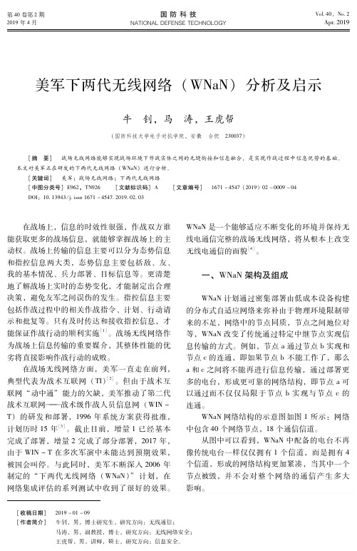
WNaN网络中应用了很多新技术,包括动态 频谱接入、自适应多收发器频率指派、多信道媒 体接入、高 度 可 扩 缩 的 路 由 以 及 容 断 组 网 等[4]。 WNaN网络中使用的无线电台在实际作战环境下 可以自组织的方式形成网络并克服频率转换带来 的中断,极大提升了整个网络的抗毁性。
(一) 动态频谱接入 下两代无线网络中的每一电台都拥有 4个信 道。动态频谱接入检测哪个频谱在使用,并自动 转移到最佳可用频率。网络中允许使用动态分布 式算法对一个节点上的接收器实现频率分配。当 网络拓扑发生改变,例如节点移动,或是列表允 许改变,或有干扰信号出现时,网络将会实施频 率的再分配。当士兵在复杂的环境中机动时,无 线局域 网 自 动 确 定 维 持 通 信 的 最 佳 频 率 和 最 佳 路径。 (二) 中断容忍 当网络遭受破坏的情况下,有些数据一时无 法实现即时传输,但其中部分数据在一定时间段 内仍然具有重要的军事价值,传统的电台网络中 这些数据将会丢失,WNaN中的电台具有中断容 忍能力,可以将有价值的数据存储下来,存储时 间可以是几秒、几分甚至一个小时或者更长,直 到找到传输数据的新路径为止。 (三) 多同步通信提高负载 与传统的单信道电台网络不同,WNaN支持 在一定区域内和相同节点多同步通信,在很大程 度上提高了整个网络的负载能力。 (四) 低成本 通过利用成熟的商用组件,WNaN中的无线 电台成本很低,预计政府每单位的大量采购成本
WNaN系 统 参 加 了 网 络 集 成 评 估 (NIE) 121,进行 了 一 系 列 演 示。作 为 正 在 评 估 的 系 统,WNaN成功在战术环境中的 102个节点上传 输语音和 数 据, 传 输 的 数 据 量 超 过 了 初 始 设 定 指标。
为了支持 NIE131,美国陆军与 DARPA合
无线应用(五)――WN322G+ V1与PSP的使用
无线应用(五)――WN322G+ V1与PSP的使用我司WN322G+(1.0)在无线网卡模式下支持PSP连接,同时在软AP模式下也支持PSP连接。
下面分别在我司WN322G+(1.0)无线网卡的两种工作模式下,来配置与PSP的连接。
∙PSP与WN322G+联机游戏设置∙PSP在WN322G+软AP模式下联网设置一、PSP与WN322G+联机游戏设置该模式下主要是通过PSP设备和支持PSP功能的无线网卡进行连接,无线网卡再通过有线连接共享来进行游戏,因此前提是你的电脑通过有线方式能够上网。
本文以TP-LINK网卡WN322G+连接SONY PSP 2000为例进行说明1、设置网卡属性首先安装好WN322G+无线网卡的驱动和客户端软件,然后打开设备管理器-网络适配器,在TL-WN322G/WN322G+ wireless USB Adapter上右键点属性,然后打开高级选项卡,一定要把PSPXLinkMode改为Enable,默认是Disable,否则PSP连接不成功。
2、设置网卡客户端打开WN322G+客户端软件,模式选择“无线网卡”,选择“更多的设置”,选择“网络连接模式”为点对点,网络名称选“任何”,其它保持默认,如果PSP上有加密,这里也要加密;我们这里没有加密,直接点击“应用”来保存设置。
然后点击下面的高级设置,勾选PSP X连接模式。
3、设置电脑的网络共享如果是拔号上网,在宽带连接上右键选择“属性”,如果通过路由器上网,在本地连接上右键选择“属性”,点击高级,勾选下面两项:这样无线网卡可以共享有线连接了,因为电脑本地连接的IP是192.168.1.10,所以要把无线网卡的IP地址设置为192.168.0.1,子网掩码:255.255.255.0,网关和DNS不填。
4、连接PSP设备PSP 2000不会主动发射无线信号,所以要先进入游戏,进行联机操作后才会发送无线信号(注意:首先要开启无线硬件开关,在设备的上侧左边:WLAN),以《怪物猎人》为例,必需进入游戏,进入“在线集会所”后,打开WN322G+客户端软件,才能在当前的可用的网络列表中扫描到PSP,点击连接,在客户端下面可以看到有发送和接收数据,表示PSP和无线网卡连接成功。
无线通信技术的发展历程与未来趋势
无线通信技术的发展历程与未来趋势随着科技的迅速发展,无线通信技术已经成为我们日常生活的重要组成部分。
本文将介绍无线通信技术的发展历程,并展望未来的趋势。
一、发展历程1. 第一代无线通信技术(1G)第一代无线通信技术是指20世纪70年代末到80年代初引入的模拟蜂窝系统。
这种技术仅支持语音通信,通信质量较差且容量有限。
然而,第一代无线通信技术奠定了无线通信的基础。
2. 第二代无线通信技术(2G)第二代无线通信技术于20世纪90年代初引入,这时数字技术开始在通信领域中使用。
2G技术使通信更加可靠,并增加了数据传输的能力。
GSM(全球移动通信系统)成为了2G技术的代表,它实现了全球范围内的无缝通信。
3. 第三代无线通信技术(3G)第三代无线通信技术于21世纪初开始使用。
3G技术实现了更高的数据传输速率,支持了更多的多媒体应用,如视频通话和移动互联网。
这一技术的引入使得人们可以随时随地访问互联网。
4. 第四代无线通信技术(4G)第四代无线通信技术于2010年代开始使用。
4G技术提供了更高的速度和更大的容量,使得高清视频、在线游戏和实时互动应用变得更加流畅。
LTE(长期演进)和WiMAX(全球互操作性微波访问)是4G技术的主要标准。
5. 第五代无线通信技术(5G)第五代无线通信技术是目前最先进的无线通信技术。
5G技术将实现比4G更快的速度、更低的延迟和更大的容量。
它将支持更多的设备连接,并推动物联网和智能城市的发展。
二、未来趋势1. 物联网的普及随着5G技术的发展,物联网将成为现实。
物联网允许各种设备和传感器通过互联网相互连接和交流。
这将极大地改变我们的生活方式,促进智能家居、智能交通和智慧医疗等领域的发展。
2. 跨行业合作的加强无线通信技术的发展将会促使各行各业之间的合作加强。
我们将看到更多的跨行业合作,以实现更高效的通信和更多创新性的解决方案。
3. 边缘计算的应用边缘计算是将计算能力和存储资源放置在接近数据源的位置。
KBC Networks WES3 第三代无许可5GHz无线以太网系统快速启动指南说明书
Quick Start GuideWES3IntroductionWelcome to KBC Networks’ Quick Start Guide for the WES3, 3rd generationunlicensed 5GHz Wireless Ethernet System. This guide has been designed toprovide a step-by-step guide to setting up a WES3 wireless link.Each WES3 RF module includes user-selectable firmware that allows any WES3model to be configured as an AP/Host or a Client providing a simpler approach tocreating and expanding point-to-point and point to multipoint wireless networks.DownloadsFull specifications, features and additional information can be found on the relevant product page on the KBC website here as well as in the downloads section: /resources/downloads. GeneralCheck the product upon receipt for any visible damage which may have been caused during shipping. Claims and discrepancies must be reported within 1 week of original product shipment from KBC. See below for model numbers and system contents.Part Numbers – Individual UnitsModel Number For use in: Antenna Power Requirement Field of ViewWES3-AX-CA Americas17dbi directional 24Vdc passive PoEUnit is supplied with powerQSG-WES3_Series-Rev1807 Copyright © KBC Networks Ltd. 2018WES3-KT-POE (2) WES3-AX-CF 192.168.1.200 192.168.1.201 --WES3-EDG-KT (2) WES3-AX-CA 192.168.1.200 192.168.1.201 (2) ED-G System Contents – WES3-AX-CA /-CB, -CC, -CE & WES3-AX-BA /-BB, -BC, -BE VersionsQty Description1 WES3 RF module with integrated directional antenna1 24Vdc power supply with integrated PoE injector – non PoE version only, please see table below 1 Strain-relief external RJ45 LAN port seal1 Quick Start Guide1 WES3 Pole/Wall Mounting Kit which includes:Qty Description1Pole clamp bracket1Bracket body (L/R swivel piece)2Connecting pieces (up/down alignment)250mm, 1.98” long 1/4” hex bolt2¼” hex nuts127mm, 1.06” long ¼” hex bolt2Flat washers 15mm, 0.59”2Locking washers 10mm, 0.39” long1U-bolt2¼” lock washersNote: all versions of WES3 units contain the above list of pole/wall mounting assembly kits.System Contents – WES3-AX-AA /-AB, -AC, -AE Omni-Directional VersionsQty Description1 WES3 RF module with (2) external N-connector antenna ports1 24Vdc power supply with integrated PoE injector – non PoE version only, please see table below 1Strain-relief external RJ45 LAN port seal2 5 dBi Omni-directional Antennas1 Quick Start Guide1 WES3 Pole/Wall Mounting KitSystem Contents – WES3-AX-CF /-CG & WES3-AX-BF /-BG VersionsQty Description1 WES3 PoE powered RF module with integrated directional antenna1 Strain-relief external RJ45 LAN port seal1 Quick Start Guide1 WES3 Pole/Wall Mounting KitNote: This version assumes that an IEEE802.3af PSE device is available to power the WES3 radio. No injectors or power supplies are provided.System Contents – WES3-AX-AF /-AG Omni-Directional VersionsQty Description1 WES3 PoE powered RF module with (2) external N-connector antenna ports1Strain-relief external RJ45 LAN port seal2 5 dBi Omni-directional Antennas1 Quick Start Guide1 WES3 Pole/Wall Mounting KitNote: This version assumes that an IEEE802.3af PSE device is available to power the WES3 radio. No injectors or power supplies are provided.QSG-WES3_Series-Rev1807www.kbcnetworks .comCopyright © KBC Networks Ltd. 2018Physical DeploymentThis equipment must be installed and operated in accordance with instructions found in this document. Failure to comply with these instructions will invalidate warranty.All wireless units should be programmed and bench tested install installation. KBC recommends creating a master network diagram to record all IP addresses and key network information.WES3 Factory Default Settings (unless ordered in WES3-KT or similar kits or pre-configured systems when “KBC-PRE-CONF” service was ordered)Parameter Setting LAN IP Address 192.168.1.202 GUI User Nameadmin GUI PasswordpasswordModeAccess Point (WDS)Channel/Frequency161 (5.805 GHz) Channel Spectrum Width 20/40 SSIDKBC_WES3 Pre-shared Key 11111111 MAC-Filter Disabled TX Power Output Max Antenna Gain 17Connecting to a WES3 RF ModuleKBC Networks recommends shielded, outdoor-rated, straight-through Ethernet cables when connecting near power outlets and when exposed to the elements. 24V PASSIVE POE INPUT 48V 802.3af POE INPUTWES3-AX-CA /-CB, -CC & -CE WES3-AX-CF /-CG WES3-AX-BA /-BB, -BC & -BE WES3-AX-BF /-BG WES3-AX-AA /-AB, -AC & -AE WES3-AX-AF /-AGWES3-PIM-WP: 24Vdc power supplywith integrated PoE injector POE Port WES3 RF ModuleIEEE802.3af standard PoE switch(Americas Only) Remote Power Solutions AvailableYou may also be using a KBC “Power Box” for the Client unit at the pole. In that case you would not power via the supplied injector but rather from the pass through injector built-into the “SPB” power enclosure. The following are optional power solutions which are available (Americas only) and support the WES3 series:Model Powers/ConnectsKBC-SPB-1AF-24 One <15W draw IP camera and one 24V POE input WES3 series node (eg WES3-AX-CA) KBC-SPB-1AT-24 One <30W draw IP camera and one 24V POE input WES3 series node (eg WES3-AX-CA) KBC-SPB-1AT-48 One <30W draw IP camera and one 48V POE input WES3 series node (eg WES3-AX-CF) KBC-SPB-4AF-24 Up to 4 <15W draw IP cameras and (1) 24V POE input WES3 series node (WES3-AX-CA) KBC-SPB-4AF-48 Up to 4 <15W draw IP cameras and (1) 48V POE input WES3 series node (WES3-AX-CF) KBC-SPB-24-24 (2) 24V POE WES3 series nodes (ie WES3-AX-CA) in a relay format in a location where are no cameras to connect at that specific location.KBC-SPB-48-48 (2) 48V POE WES3 series nodes (ie WES3-AX-CF) in a relay format in a location where are no cameras to connect at that specific location.KBC-SPB-4AF-48 Up to 3 <15W draw cameras (or one 30W camera) and (2) 48V POE WES3 series nodes in a wireless relay format in a location where are cameras to connect as well.KBC-SPB-HPoE-24 One <70W draw IP PTZ and one 24V POE WES3 series node (ie WES3-AX-CA)KBC-SPB-HPoE-48 One <70W draw IP PTZ and one 48V POE WES3 series node (ie WES3-AX-CF)KBC-SPB-4AF-48-70W One <70W draw IP PTZ and either two (2) 48V POE WES3 series nodes or one additional low wattage draw camera and a single 48V POE WES3 series nodeRemote power and connection to the wireless transceiver can also be made via KBC’s line of industrial battery backup UPS or solar power kits to maintain 24/7 power when onsite power is either inconsistent or unavailable. For more info see the power section of our website here. Contact KBC for info on what is needed for the correct power input.Configuring WES3 for Point-to-Point and Point to MultipointPTP = Point-to-Point / PTMP = Point to MultipointConfiguring the AP/Host Antenna1.Set laptop to static IP on 192.168.1.xxx network2.Connect to WES3 RF module as shown in previous section.3.Once WES3 RF module is connected to power source, the power LED light on the back of the unit willturn on. After 30-60 seconds you may hear the WES3 “beep”, which is normal, alerting you that it is booted up.4.Once WES3 is connected to laptop or switch the network LED on the back of the unit will turn and flashto indicate link activityOpen a web browser and type in the factory default IP address 192.168.1.202. If no response: you may be using a kit (see note in orange below) or a pre-configured system.KBC-SPB-4AF-48 or KBC-SPB-4AF-24 KBC-SPB-1AF-24 or KBC-SPB-1AT-24 /-48QSG-WES3_Series-Rev1807www.kbcnetworks .comCopyright © KBC Networks Ltd. 2018Note: factory pre-configured “kitted” WES3 units (ie WES3-KT and WES3-KT-POE) are set to 192.168.1.200 for the Host unit and 192.168.1.201 for the Client device.If using a WES3-KT, WES3-KT-P5, WES3-KT-P5T, WES3-EDG-KT or a pre-configured system using “KBC-PRE-CONF” service code, skip the following configuration steps and go to the “Instructions for Physical Deployment” at the bottom of this guide.5. Enter ‘password’ to access the Status page6. The first step is to change the LAN IP Address. Click the Network tab then click ‘Edit’7. Change the IP Address then click ‘Save & Apply’8. After the IP address is updated – it will take you back to the Login page and your browser will now be atthe new IP address. If you don’t get to the Login page make sure you don’t have an IP address conflict and ensure your laptop is set to the same network range (subnet) as the WES3.9. Now that you have logged back in – notice you are on the Status pagepassword• Highlighted are the SSID & Radio MAC Address (shown as ‘APHost MAC')• For each PTP and PTMP wireless system to connect, the APHost and client(s) need to benetworked together using the SSID and Radio MAC Address fields • KBC recommends the APHost and Client(s) share a unique SSID.• KBC also recommends the APHost be MAC locked to each client and each client should be MAClocked to its APHost• The radio MAC address can be found on the Status page (as shown above) as well as on the backof each WES3 RF module (as follows)10.11. Now in the Wireless Settings – Confirm that the SSID matches each client antenna. If you change theSSID click ‘Save & Apply’12. Click on the MAC Filter tab if this feature is desired. It is recommended for enhanced security, howevernot required for the radios to link.13. Enable the MAC-Address filter by clicking on the drop down menu to select ‘Allow listed only’ 14. Enter the radio MAC Address of each client antenna in the box15. To enter more than one radio MAC address, click the green + icon to add another field 16. When complete click ‘Save & Apply’17. If there is more than one PTP or PTMP system at one location, each APHost needs to be set to a differentunique channel or frequency. Select the channel. 18. Click ‘Save & Apply’Radio MAC Address listed here on back of every WES3 antennaQSG-WES3_Series-Rev1807 www.kbcnetworks .com Copyright © KBC Networks Ltd. 2018Configuring the Client Antenna19. Leave WES3 APHost antenna plugged in and powered up. Connect directly to the client antenna andrepeat steps 1-1120. Look at the bottom of the page under ‘Wireless Interface’ on the ‘General Setup’ tab. Look at the ‘Mode’field and select ‘Client (WDS)” from the drop-down menu.21. Verify that the SSID matches the SSID of the APHost antenna.22. Enter the radio MAC address of the AP host antenna into the “Remote MAC” field. For help see step 10.23. Click “Save & Apply”24. Now the Client and APHost are wirelessly connected. Verify wireless connection by looking at the‘Connection Status’ information.25. KBC recommends that the wireless signal strength is greater than 40 but less than 70.• Wireless Signal Strength = difference between noise & signal✓ Signal = - 36dbm ✓ Noise = - 95dbm✓ Wireless Signal Strength = 59dbm (ie, in the 40-65 range)26. You can also confirm that the wireless status bar is close to 100%27. While there is a frequency selection on the Client interface, the frequency is always driven by the APHostso no matter what channel for which the Client is selected, it will connect to its Host frequency provided that the SSID, PSK and radio MAC-filter security feature (if enabled) are all entered correctly to link wirelessly.28. The same information can be found on the Status page29.APHost in the field provided. Click on the Ping start button and confirm that you get 5 packetstransmitted and received with 0% packet loss. The average ping time should be under 10ms for most applications. Please contact KBC Networks technical support if this test fails.Connecting multiple standard WES3 Clients to a High Throughput Host/AP (ie WES3HTG series)Some systems require the use of a high throughput series ‘receiver’. The WES3 series can link to the WES3HTG provided several parameters match up. Parameter WES3 Default Setting WES3HTG Default Setting Field reconfiguration to:LAN IP192.168.1.202 192.168.1.152 Ensure that all WES3 / WES3HTG units have independent IP Addresses to avoid IP Conflicts. Record all IP changes! GUI User Name admin admin N/A GUI Password passwordpasswordN/AHost/Client ModeHost (Access Point WDS)Host (Access Point WDS)All WES3 units change to Client WDS; keep WES3HTG in Access Point WDS Mode.Channel/Freq 161 (5.805 GHz) 161 (5.805 GHz) N/A (unless a more appropriate frequency is needed in the environment)Spectrum Width 20/40 20/40/80 N/A (unless a more appropriate spectrum width is needed in the environment)SSIDKBC_WES3 WES3HTG All Clients must match Host setting; change to your desire. Record changes.Pre-shared Key11111111 11111111 No required changes, however, KBC recommends changing from default for security purposes.Remote MACN/AN/AOnly applicable to Client Mode: enter radio MAC of WES3HTG Host if this setting is desired (recommended).MAC-Filter Disabled Disabled Only applicable to Access Point Mode: enter radio MAC of each remote wireless Client unit to be connected to the Host if this setting is desired (recommended). TX Power Output MaxMaxN/AAntenna Gain17 17Change WES3HTG Host to appropriate setting depending on the model number: WES3HTG-AX-AA → 5 WES3HTG-AX-BA → 9WES3HTG-AX-CA (keep at 17)QSG-WES3_Series-Rev1807www.kbcnetworks .comCopyright © KBC Networks Ltd. 2018Instructions for Physical DeploymentThis equipment must be installed and operated in accordance with instructions found in the KBC Networks’ manual. Damage due to misuse is not covered by warranty.1. Feed the Ethernet cable through the black weather coupler protection piece prior to crimping on the RJ45connector.2. Hand-tighten the Ethernet cable connection protecting piece, do not tighten further. Damage due to over-tightening the black weather coupler into its RJ45 housing is not covered under warranty.3. The Ethernet cable should have wiggle room to allow condensation to release. Leave a gap small enoughto keep out bugs and such but open to allow moisture to release and drip down the cable away from the port.4. Do not mount the antennas horizontally or upside down. The black external LAN port should pointdownwards.5. Once the cable is inserted into the external LAN port RJ45, a small flat head screwdriver, or similar tool,is needed to release the tab of the RJ45 connector on your cable. If you pull the cable without releasing the tab, it will damage the port.Trouble-shootingContact KBC for technical assistance. Here are some ideas to try. ProblemSuggestionNo signal strength LEDsEnsure Host in Access Point WDS mode and Client(s) in Client WDS mode. Ensure that all Clients are set to matching parameters as Host. Many times when the MAC filter is enabled there is an incorrect character. Verify all characters match exactly or try disabling anderasing the “Remote MAC” from the Client side (and MAC-Filter on the Host). If they link after disabling that feature then it is likely that an incorrect MAC or character was used.Not all signal strength LEDs light upEnsure clear wide-open line of sight. If you have even just one signal strength LED then the configurations are likely correct. Try improving the alignment of the antennas and/or another frequency in case the problem is related to RF interference in the environment.Unit reboots itself continuously after a couple of minutesThe “Ping Watchdog” feature may be turned on and is configuredimproperly. Check the feature (system/tools) and disable to see if the constant auto-reboot stops.Unit stops connecting to mate antenna until a power reset is performedThis is symptomatic of 3rd party RF interference. Attempt the following suggestions:Run a scan from the Host (Network/Wireless/Spectrum) todetermine the least noisy frequency and set the Host to that channel.Reduce channel spectrum widthLower power output or try another antenna gain option Enable one of the self-healing tools such as aout-reboot byhours or ping watchdog.No Network LEDCheck all Ethernet cabling and LAN ports on all devices connected to WES3HTG unit.No access to GUI; cannot ping IP **NOTE: your system may have been pre-configured.Check provided documentation for unit IP address per serial number. If working with one of the kits, the default IP is either 192.168.1.200 or 192.168.1.201. The IP would only be 192.168.1.202 after performing a hard reset (see warning for this process below; reset as final option). It is important to record all changes. If the IP address is changed from default there is no way to recover it if forgotten other than a restore to defaults. Having to hard reset will be a time consuming effort.WES3 LED Status Indicators↑Flashing LED Solid LED LED offWSS Wireless Signal Strength (see #26)1. RSSI4/STATUS ↑In power-up / boot-up process40+ RSSIWSS less than 40 or no wireless link2. RSSI3 30-39 RSSIWSS less than 30 or no wireless link3. RSSI2 20-29 RSSIWSS less than 20 or no wireless link4. RSS1 10-19 RSSIWSS less than 10 or no wireless link5. NETWORK – Ethernet link activity - LAN Link activity established↑Link activity from wireless unit to connectedEthernet device or across wireless linkNo link to Ethernet cable connected device(not indicative of wireless link/strength)6. Power Power appliedNo power to unit.Note:The LEDs do not change color.Factory Reset to Default via GUI1.Click on ‘System’ then ‘Firmware’2.Click on ‘Perform Reset’Factory Reset to Default via Hard Reset ButtonWARNING: A hard reset to defaults will erase all saved info including the system requirements for a wireless connection. When possible, save a copy of the config file to a known and accessible location and record all changes made to the WES3 device.RESET AT USER RISK: Incorrect reset procedure can result in damage to the internal board and require a return to KBC Networks or need for replacement at user cost. If the button is pushed but not held for the duration of the reset process it MUST be powered down and retry. Do not press the button without powering down and restarting.1.Power up the WES3 RF module and allow it to go through its power up process.2.Remove the Phillips head screw near the port on the bottom of the WES3 RF module.3.Insert a small screwdriver or paperclip into screw hole in order to push the reset button.4.Hold the button for 12-15 seconds and release.5.RF module will reset to the WES3 factory default settings found on page 1 of this guide.Warranty InformationSee our website at: https:///policies-procedures/general-content/about-us/policies-procedures for warranty information covering all of KBC Networks products.ComplianceFCCChanges or modifications not expressly approved by the party responsible for compliance could void the user’s authority to operate the equipment. This device complies with Part 15 of the FCC Rules. Operation is subject to the following two conditions:•This device may not cause harmful interference, and•This device must accept any interference received, including interference that may cause undesired operation.This equipment has been tested and found to comply with the limits for a Class A digital device, pursuant to part 15 of the FCC Rules. These limits are designed to provide reasonable protection against harmful interference when the equipment is operated in a commercial environment. This equipment generates, uses, and can radiate radio frequency energy and, if not installed and used in accordance with the instruction manual, may cause harmful interference to radio communications. Operations of this equipment in a residential area is likely to cause harmful interference in which case the user will be required to correct the interference at his own expense.Industry CanadaThis Class A digital apparatus complies with Canadian ICES-003. To reduce potential radio interference to other users, the antenna type and its gain should be so chosen that the equivalent isotropically radiated power (E.I.R.P.) is not more than that permitted for successful communication. This device complies with Industry Canada license-exempt RSS standard(s).Operation is subject to the following two conditions:•This device may not cause interference, and•This device must accept any interference, including interference that may cause undesired operation of the device.Cet appareil numérique de la classe A est confrome à la norme NMB-003 Canada. Pour réduire le risqued’interférence aux autres utilisateurs, le type d’antenne et son gain doivent être choisies de façon que la puissance isotrope rayonnée équivalente (PIRE) ne dépasse pas ce qui est nécessairepour une communication réussie. Cet appareil est conforme à la norme RSS Industrie Canada exempts de licence norme(s). Son fonctionnement est soumis aux deux conditions suivantes:17 Compliance•Cet appareil ne peut pas provoquer d’interférences et•Cet appareil doit accepter toute interférence, y compris les interférences qui peuvent causer un mauvais fonctionnement du dispositif.CE MarkingCE marking on this product represents the product is in compliance with all directives that are applicable to it.This equipment may be operated in the following countries:Great Britain and Northern Ireland, Austria, Belgium, Denmark, Finland, France, Germany, Ireland, Italy, Netherlands, Norway, Portugal, Romania, Switzerland, Sweden.Installer Compliance ResponsibilityDevices must be professionally installed and it is the professional installer's responsibility to make sure the device is operated within local country regulatory requirements.RoHS/WEEE Compliance StatementEuropean Directive 2002/96/EC requires that the equipment bearing this symbol on the product and/or its packaging must not be disposed of with unsorted municipal waste. The symbol indicates that this product should be disposed of separately from regular household waste streams. It is your responsibility to dispose of this and other electric and electronic equipment via designated collection facilities appointed by the governmentQSG-WES3_Series-Rev1807 Copyright © KBC Networks Ltd. 2018or local authorities. Correct disposal and recycling will help prevent potential negative consequences to the environment and human health. For more detailed information about the disposal of your old equipment, please contact your local authorities, waste disposal service, or the shop where you purchased the product.Need Help?Please visit our website or contact your nearest KBC office or dealer.KBC Networks Office Contact InformationNorth & Latin America, USAPhone: +1 949 297 4930Toll-free: +1 888 366 4276Email: ***************************EMEA, UKPhone:+44(0)1622 618787Email: *******************************APACChinaPhone (1): +86 25 8688 3321Phone (2): +86 25 8688 4058Email: ***************************SingaporePhone: +65 98463323Email: *******************************。
下一代无线通信技术的发展
下一代无线通信技术的发展随着科技不断的发展,人类已经进入了物联网时代。
物联网作为一种新兴技术,以其可以为人们提供便利的特点,被广泛的应用在各种领域。
而物联网的实现离不开一项重要的技术——无线通信技术。
随着生活中的不断发展和应用的广泛,我们已逐渐相信:未来无线通信技术必将成为各种智能终端实现连接和互联的技术基础,同时也将会成为物联网技术的基础,为推进人类实现物质的智能化、自动化和数字化等发展提供有力支撑。
下一代无线通信技术的发展势在必行。
本文将从技术、应用和前景三个方面阐述下一代无线通信技术的发展。
一、技术方面无线通信技术已经走过了数十年的发展,从1G、2G到3G以及4G,每一个技术标准的出现都代表着无线通信技术向更快,更可靠、更智能的目标迈进。
由于数据传输的高速、低延迟以及超高可靠性将是业界所追求的技术目标,这或许就是5G不断追求的性能指标。
现有的移动通信技术面临着巨大的挑战和发展空间。
5G的最大亮点是新空口(新的调制方式、新的信号结构、新的时空信源码、新的帧、新的子载波间距、将所有网络集成在更高频率范围),进一步增加了频谱利用率,为网络的高速传输和带宽扩展提供了更好的基础。
二、应用方面在日常生活中,我们已经感受到了4G的强大速度和流畅体验,但伴随着物联网的到来,4G的能力也已不足以满足人们对移动宽带的需求。
特别在5G产业链建设中,基础性设备、芯片设计、软件及演示等涉及的领域繁杂,系统复杂。
而这些应用伴随着共建共享的概念,可以更好地为人们提供更为智能、便捷的服务以及需要实现的目标。
同时,无处不在的智能化,让人工智能、5G与人类工作、生产、生活紧密结合在一起,为人类带来的更多的机会和选择。
三、发展前景在5G的发展趋势中,具有革命性的技术和全新的应用模式将会逐渐形成和应用,将会覆盖人们的工作、学习、游戏、日常生活和生产等多个方面。
5G对于传统领域,将进行改造并加速智能化,对于新兴领域将进行创新及拓展,而这些应用也对于5G技术更高的要求和发展提供了保障。
- 1、下载文档前请自行甄别文档内容的完整性,平台不提供额外的编辑、内容补充、找答案等附加服务。
- 2、"仅部分预览"的文档,不可在线预览部分如存在完整性等问题,可反馈申请退款(可完整预览的文档不适用该条件!)。
- 3、如文档侵犯您的权益,请联系客服反馈,我们会尽快为您处理(人工客服工作时间:9:00-18:30)。
16
组织图
XGP论坛总会
若尾副议长 ARIB专务理事
井上议长 TTC专务理事
近副议长 WILLCOM符社长
Mr. Sam Endy 副议长 高级顾问
XGP论坛干事会
杉浦秘书长
佐藤BWG议长 高级顾问
河和TWG议长 Willcom部长
赤冢PWG议长 京瓷部长
吉田OWG 议长 京瓷部长
Copyright 2009 XGP Forum All Rights Reserved.
下一代高速无线通讯方式 XGP
2009年7月
XGP 论坛
Copyright 2008 XGP Forum All Rights Reserved.
1.XGP 技术特征 2.XGP 论坛
Copyright 2009 XGP Forum All Rights Reserved.
2
XGP的优越特性
◆易操作,大容量,高速度无线通讯系统
该工作组讨论关于通讯网络最优化的各项提案,并且为运营商提供对现有网络的检查和诊断。该工作组通过与运营商,以及设备 商的协同合作推进执行诊断和优化网络的工作。通过网络优化,服务质量得到飞跃性的提高,与此同时,优化技术为合作伙伴-暨参与网络优化工程的当地运营商或设备商--所共有,从而帮助实现利用XGP技术的运营商和设备商的整体技术水平的提高。
10
特征3:和AAS的兼容性① 基站AAS利用上传的传输路径特性来决定下载的送信 重量,此方式保障终端收信信号的最优化。
TDD(时分多址方式)对于 下载和上传采用相同的传输 路径特性。 FDD(频分多址方式)对于 下载和上传采用不同传输路 径特征。
Up Link AAS
送信重量
Rx
Down Link AAS
实现高效链接,改善室内渗透,使宏蜂窝有效纳入系统。 抑制系统内信号干扰,容量和信息处理量扩大。 抑制传输路径变更(频率选择性信号衰减),确保安定通讯,信息处理能 力大幅提高。
Copyright 2009 XGP Forum All Rights Reser
◇传输速度 (带宽 10MHz)
传输速度:256QAM XGP
(256QAM~BPSK)
传输速度:64QAM
DL:16.3Mbps UL:14.9Mbps DL:20.7Mbps UL:11.5Mbps DL:24.9Mbps UL:16.8Mbps
服务区域示意图
DL:22.8Mbps UL:20.8Mbps No correspondence
Copyright 2009 XGP Forum All Rights Reserved.
18
会员名录
会员名录
(* 号会员为干事会员) Company Name
Country/Area
Country/Area Company Name 1 ABIT Corporation Japan 2 ACCESS Co., Ltd. Japan 3 Alcatel-Lucent China China 4 Altair Semiconductor Ltd Israel 5 Altel Inc. Japan 6 Anritsu Corporation Japan 7 ArrayComm, LLC. USA 8 Asia Wireless Thailand 9 BDA China Limited China 10 Couei Corporation Japan 11 Daiwa Institute of Research Japan 12 First International Telecom Taiwan 13 Freescale Semiconductor USA 14 Group Sense Ltd. China (HK) 15 Hitachi Kokusai Electric Inc. Japan *16 Hitachi, Ltd. Japan 17 HP Japan Japan 18 Inventec Appliances China *19 JAPAN RADIO Co., Ltd. Japan 20 KAGA Electronic Co., LTD Japan
13
XGP运用方案
移动中的数据传输
家居保安 现场保安 家庭录像伺服器
急救和医疗
儿童安全监控
特殊用途特殊设定 远程监控系统 Drive recorder
Copyright 2009 XGP Forum All Rights Reserved.
14
总结
XGP : 无线宽带系统的最佳解决方案
提供高实用速度,高安定性能的通讯
9
特征3:AAS的特长②
AAS方式的基站信号是由复数个传输信号合成的。终端可稳 定的收信。 抑制频率选择性信号衰减,实现稳定通讯。 信息处理能力大幅提高
Omni 方式
3条的合成波
AAS 方式 无线电频率 Omni和AAS的收信信号(例)
Copyright 2009 XGP Forum All Rights Reserved.
高速通讯 (~100Mbps)
信号形成 零点形成
技术保障高频率利用效率:
AAS ( 自适应阵列天线系统) ADC( 自律分散控制 ) SDMA (空分多址技术) MIMO ( 多天线输入/输出技术)
自适应天线的运用
Copyright 2009 XGP Forum All Rights Reserved.
WiMAX
(64QAM~QPSK)
LTE
(64QAM~BPSK)
No correspondence
Extract from report by frequency utilization policy committee
◇服务区域示意图
相对传输速度
0.17 0.33 0.67
1.0
1.33
256QAM 64QAM 16QAM QPSK BPSK
Up LINK Down LINK 2.5msec 2.5msec
Up LINK Down LINK 3.3msec 1.7msec
12
Copyright 2009 XGP Forum All Rights Reserved.
XGP的优越性
~对应灵活的系统设计需要~
<例>
・ 宏蜂窝和微蜂窝可以在同一区域重复置局。网络优化进程可以根据需要个别进行。 - 微蜂窝 : 重视实效速度的变调方式 - 宏蜂窝 : 重视高速移动的变调方式
Copyright 2009 XGP Forum All Rights Reserved.
4
XGP的3个最大特征
特征1. 上行同样高速化
适用于实时直播,以及针对特殊客户的特殊设定。
特征2. 自律分散控制,干扰回避功能 (XGP独有)
初期建网,基站增设设计灵活自由。 同一区域的重复置局成为可能。
特征3. 和AAS (自适应阵列天线系统)具良好兼容性
可信赖的技术支持
XGP技术基于服务15年的PHS系统,并灵活利用TDD的智能天线等优势技术。该系统不仅拥有丰富的经 验而且值得信赖。
Copyright 2009 XGP Forum All Rights Reserved.
15
1.XGP 技术特征 2.XGP 论坛
Copyright 2009 XGP Forum All Rights Reserved.
高效利用频段资源(微蜂窝结构, 自适应阵列天线系统技术) ⇒ 大容量,高速度通讯 置局的高度灵活性 (自律分散控制, 动态信道分配) ⇒易操作
宽带通讯技术 TDD技术的优势
・ 自律分散控制, 动态信道分配 ・ 微蜂窝结构
无须置局设计
・OFDM方式 ・高效率,高输出增幅
大容量 (微蜂窝)
Microcell method
TWG (Technical Working Group)
该工作组负责所有关于XGP技术方面的讨论和支持。它的工作核心是为提供适用服务而展开的XGP技术的标准化活动。 其它活 动内容也包括:支持解决关于XGP技术的新课题,新兴服务项目的标准化,与其他的标准化团体的技术交流,对运营商进行技术培 训等。该工作组下设若干专项工作小组讨论个别技术议案。专项小组成员必须是XGP会员,并亲自参与进行规格制定的各项具体 工作。专项小组工作及讨论内容只限小组成员内部公开。
3
主要规格指标
■ XGP 最终性能
传输速度 移动性 呼叫时间 最大蜂窝半径 : 100 Mbps 至 160Mbps : 时速300km接续可能 : 低于 5msec : 5km以上
※ 系统主要指标
接入方式 框架结构 #/TDMA #/OFDMA 信道宽度 子信道宽度 变调率 OFDMA/TDMA-TDD 5mS Symmetric Frame 8Slot (Uplink:4slot+Downlink:4slot) Depends upon sub-channel width 2.5/5/10/20MHz 37.5kHz BPSK,QPSK,16/64/256QAM
PWG (Promotion Working Group)
该工作组的主要任务是让XGP这个技术得到广泛认同。为此,该工作组通过网站维护及更新,电子杂志的发行,在展览会和技术 交流会等场合发布XGP入门指南,XGP用途简介等宣传册,使这个技术及其服务在世界各地以各种形式被广泛采纳和运用。
OWG (Optimization Working Group)
Tx
AAS和TDD具高度兼容性
Copyright 2009 XGP Forum All Rights Reserved.
11
特征3:和AAS的兼容性② TDD方式: 如上传和下载的传输时间/频率带的差异增大,传 输路径特性将随之改变。
XGP系统中,上传和下载的间隔频段仅为2.5ms,因此 改变极少。 最大程度发挥AAS的功效。 XGP一定利用同一带域。移动WiMAX和LTE系统中, 不限定利用同一带域。 AAS的功效难以发挥。