200万高清 双滤光片切换器 ZHM12A-20-2.5规格书
光电切换器商品说明说明书
Optional timer Delay on operate Delay on release One shot
Environment Overvoltage category
Pollution degree
Degree of protection Temperature
Delivery Contents
• Photoelectric switch: PMR • Cable gland • Installation instruction • Mounting bracket • Packaging: Corrugated cardboard (environmentally
PMR 10R G PMR 10R I
Specifications
Rated operating dist. (Sn) (0 to 5,000 lux)
Rated operational volt. (UB) (AC: 45 to 65 Hz)
Rated operational power (Relay ON)
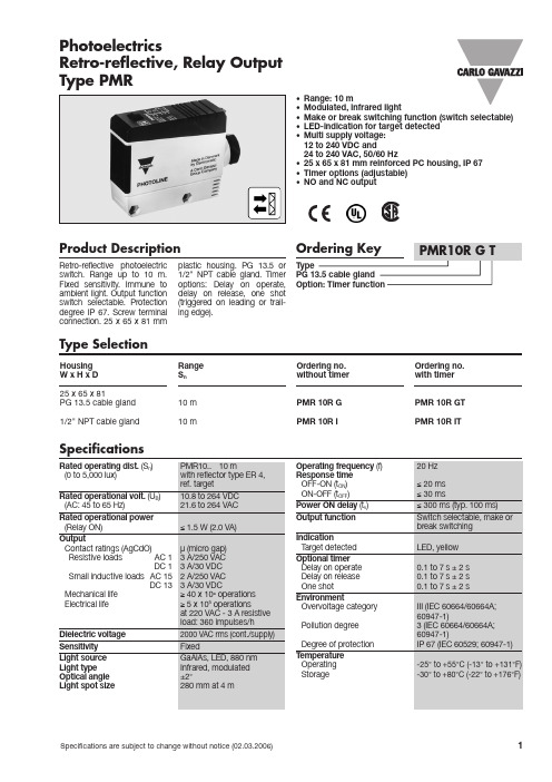
12 to 240 VDC and 24 to 240 VAC, 50/60 Hz • 25 x 65 x 81 mm reinforced PC housing, IP 67 • Timer options (adjustable) • NO and NC output
Product Description
110 g UL, CSA
Yes
Connection Diagram
Time adjustment (optional)
1 Break switching
2 Make switching
阿布拉康网络转换器产品说明书

ALANC100014.6 x 3.4 x 3.5 mmRoHS/RoHS II CompliantMSL Level = 1Request Samples Check InventoryPart Number Insertion Loss(dB Max)Return Loss (dB Min) 1-100 MHz100-200MHz 1-40 MHz40 -200MHzALANC10001-EEB30.81.22514.5Part NumberInductance (uH Min) Leakage Inductance (uH ) Interwinding Capacitance (pF Max) DC Resistance (Ω Max) Hi Pot (VAC) Weight (g) Test Condition @100kHz, 0.1V, 0mA DC Bias@ 100KHz, 0.1V@ 100KHz, 0.2VPins 1-2 Pins 4-5 60 sec. Per Piece ALANC10001-EEB31500.5351.21.215000.228ALANC10001 series is RoHS/ RoHS II Compliant and Pb free. Moisture Sensitivity Level (MSL) – Level 1Applicable Standards: IEEE 802.3u and 802.3ab Operating Temperature: -40˚C ~ +85˚CStorage Condition: -40˚C ~ +85˚C (on board),• Uniform transformer windings • Fully automated production lines • Meets IEEE 802.3u and 802.3ab standards • Compatible with 10 BASE-T, 100 BASE-TX and 1000 BASE-T • Symmetric Orientation • Operating temperature range up to -40°C to +85°C •RoHS Compliant•1CT:1CT Transformer • Fast and gigabit Ethernet • Servers, switches and routers• IP cameras, surveillance, and phone • Access points• Industrial computers and robotics • Networking and communications • Broadcast video •Set top boxFeaturesElectrical Specifications @25ºCApplicationsALANC10001 4.6 x 3.4 x 3.5 mmRoHS/RoHS II CompliantMSL Level = 1Request Samples Check InventoryALANC10001 -Marking Method = Ink MarkingOperating Temp. D: -40°C ~ +85°CSchematic EB3Package Size E:6-Pin Packaging T: 2.0K pcs/reel B: BulkPart Identification Polarity MarkingALANC10001 4.6 x 3.4 x 3.5 mmRoHS/RoHS II CompliantMSL Level = 1Request Samples Check InventoryE: 6-pinDimensions: mmA B C 4.60 ±0.203.40 ±0.20 3.50 ±0.20Coplanarity 0.10 MAXMechanical SpecificationsRecommended Land PatternALANC10001 4.6 x 3.4 x 3.5 mmRoHS/RoHS II CompliantMSL Level = 1Request Samples Check Inventory6 - Pin EB3SchematicALANC10001 4.6 x 3.4 x 3.5 mmRoHS/RoHS II CompliantMSL Level = 1Request Samples Check InventoryZone Description Temperature Times 1 Preheat T SMIN ~ T SMAX 150°C ~ 200°C60 ~ 120 sec. 2 Reflow T L 217°C 60 ~ 150 sec. 3Peak heatT P 260°C20 ~ 40 sec. MAXReflow ProfileALANC100014.6 x 3.4 x 3.5 mmRoHS/RoHS II CompliantMSL Level = 1Request Samples Check InventoryTape and Reel: 2,000 pcs/reel Pieces Per Carton: 20,000 pcs Weight Per Carton: 6 kg (approx.)Dimensions of Carton:345 x 345 x 220 mmDimensions: mmA0 B0 W E F P0 P1 P2 D0 T K0 3.704.9012.00 1.75 5.50 4.00 8.00 2.00 1.50 0.40 3.70PackagingALANC10001 4.6 x 3.4 x 3.5 mmRequest Samples Check InventoryRoHS/RoHS II CompliantMSL Level = 1 Dimensions: mmATTENTION:Abracon LLC’s products are COTS – Commercial-Off-The-Shelf products; suitable for Commercial, Industrial and, where designated, Automotive Applications. Abracon’s products are not specifically designed for Military, Aviation, Aerospace, Life-dependent Medical applications or any application requiring high reliability where component failure could result in loss of life and/or property. For applications requiring high reliability and/or presenting an extreme operating environment, written consent and authorization from Abracon LLC is required. Please contact Abracon LLC for more information.。
微软电子PD70201EVB25FW-3 3.3V 25W隔离活动限制前向转换器评估板用户指南说明书

PD70201EVB25FW-33.3V/25W Isolated Active Clamp Forward Converter PDEvaluation Board User GuideRevision 1.021 About this guideThis user guide provides both description and operation procedures for Microsemi's PD70201EVB25FW-3 evaluating board. This board is used for evaluating the performance of PD70201A PD controller with integrated switching regulator, and PD70224 Dual MOSFET – Based Active Bridge Rectifier.PD70201ILQ device supports both the standard IEEE802.3at PD application interface, and a PWM controller that is used to provide the PD operational voltage.The evaluation board supports a 25 Watt, 3.3V output in its existing configuration, with no heat sink.1.1 AudienceThis user guide is intended for qualified personnel, meaning operators and technicians who have a background in basic concepts of electronics.1.2 OrganizationThis guide is divided into several sections as follows:•Chapter 1 About this Guide: Describes the objectives, audience, and organization•Chapter 2Introduction: Provides an overview about evaluation board’s main functions, features, physical characteristics and ordering information.•Chapter 3Physical Description: Provides explanation related to the physical description (switches, jumpers, connectors).•Chapter 4Electrical Characteristics: Provides electrical characteristics of the evaluation board.•Chapter 5Installation: Provides description of the installation process.•Chapter 6Test Data: Provides board test data information•Chapter 7Schematic: Provides board schematic diagram•Chapter 8List of Material: Provides board’s list of materials.•Chapter 9Board Layout:Provides board Gerber files description for all layers.1.3 Reference DocumentsPD70201 datasheet, catalogue number DS_PD70201PD70224 datasheet, catalogue number DS_PD702242 IntroductionMicrosemi’s PD70201ILQ device is part of a family of devices which are targeted for realizing the 802.3at standard PD interface.The PD interface family of devices includes the following:Device type Power capability Integrates PWMcontrollerNoPD70100 IEEE802.3at Type 1(IEEE802.3 af level)YesPD70101 IEEE802.3at Type 1(IEEE802.3 af level)PD70200 IEEE802.3at Type 2 NoPD70201 IEEE802.3at Type 2 YesPD70210(A) 2 x IEEE802.3at Type 2 (4 pair)NoHDBaseT (95W)YesPD70211 2 x IEEE802.3at Type 2 (4 pair)HDBaseT (95W)Microsemi’s PD70201EVB25FW-3 Evaluation Board (see Figure 2) provides designers with an environment needed for evaluating the performance and implementation of PD applications based on PD70201 controller.The board is using a single PD controller, PD70201ILQ, to support the Detection, Class, and Power Supplying phases on the 4 Pairs of the Cat5 cable. The board supports sync detection of the 4 pairs. PD70201ILQ supports the current of the HDBaseT over 4 Pairs, which is more than twice the power of a standard IEEE802.3AT Type 2 interface.All necessary steps and connection instructions required to install and operate this board are provided within this document.Figure 1: PD70201EVB25FW-3 Block DiagramFigure 2: PD70201EVB25FW-3 Evaluation Board – General ViewEvaluation Boards Ordering InformationMicrosemi supplies the following Evaluation Board as shown below:Ordering Number DescriptionPD70201EVB25FW-32 x IEEE802.3at Type 2 (4 pair) PD based on PD70201 device having 4 pair supply, controlling an isolated Forward converter, having a 3.3V 7.5A output.2.1 Evaluation Board FeaturesDesigned to support Data and Spare current by a single PD70201A devicePower is supplied through the 4-pairs of the Cat5 cableWall Adapter input – Standard Barrel Jack available for connecting to an external 48-54V Wall Adapter.Data pass-through connectorOn board AT detected LED indicatorOn board Power Good LED indicatorT A= -40° to +70°CRoHS compliant2.2 Physical CharacteristicsTable 1 lists evaluation board’s physical characteristics.Table 1: Physical CharacteristicsParameter ValueMechanical dimensions in mm 165 x 57 x 20 mm (L x W x H)3 Physical Description3.1 Package ContentsUpon opening the Evaluation Board package, verify the following part is included.If it seems damaged, contact local representative or Microsemi's headquarters.Package content for standard shipments is:PD70201EVB25FW-3 Evaluation Board.Wall Adapter Input Cable3.2 ConnectorsThe following sections provide both general and detailed information regarding unit’s connectors.3.2.1 Connectors TableTable 2 lists the Evaluation Board's connectors.Table 2: Connectors List#Connector Name Description1 J1 Magjack RJ45 port for Data + Power In for PSE connection2 J2 Wall Adapter Input Standard Barrel Jack used for 48V Wall Adapter. Wall adapter connection will be automatically sensed and will override the PSE power connected to J1.3 J3 Converter Output Screw terminals for easy connecting a load to 3.3V output.4 J4 RJ45 Connector An RJ45 port for Data pass – through output3.2.2 Connectors Detailed Explanation(The numbering is in reference to the numbers listed in Table 2.)1. RJ45 Connectors.See Figure 3.Table 3: RJ45 ConnectorsJ1 & J4 Pin No Signal Name DescriptionJ1 - 1, 2 Data and Power In Data and power input to powered device (PoE Master Negative data port)J1 - 3, 6 Data and Power In Data and power input to powered device (PoE Master Positive data port)J1 - 4, 5 Data and Power In Data and power input to powered device (PoE Master Positive data port)J1 - 7, 8 Data and Power In Data and power input to powered device (PoE Master Negative data port)J1 & J4 Pin No Signal Name DescriptionJ4 - 1, 2 Data Output Isolated data pass-through to external monitoring device.J4 - 3, 6 Data Output Isolated data pass-through to external monitoring device.J4 - 4, 5 Data Output Isolated data pass-through to external monitoring device.J4 - 7, 8 Data Output Isolated data pass-through to external monitoring device.Figure 3: Front RJ45 and Auxiliary 48V Wall Adapter Connectors2. Wall Adapter ConnectionsSee Figure 3.J2 Pin No Signal Name Description Center Pin VIN (+) 42V to 57V input from wall adapter.Outer Barrel VIN (-) Wall Adapter Return3. V out ConnectionsSee Figure 4.Table 4: Output Load ConnectionsPin No. Signal Name Description J3 - 2 Vout (-) Return of DC-DC output voltage J3 - 1 Vout (+) Positive DC-DC output voltageFigure 4: V out Connections3.3 IndicationsThe following sections provide general information regarding unit’s indications.3.3.1 LED IndicationSee Figure 5.D16 is the AT_FLAG indication LED, a PD70201 device output signal indicating the device has detected a 2 finger class event from the PSE side in the class stage.D5 is the Power Good indication, a PD70201 device output signal indicating presence of PoE power.D14 is the input power indicator, indication power presence from either PoE or auxiliary source (wall adapter).Figure 5: LED Indications4 Electrical CharacteristicsEvaluation board’s electrical characteristics are described below:Table 5: Electrical CharacteristicsParameter Min MaxMain DCSupply –42*57VJ1, VIN+,VINRTNWallAdapter4257VSupply –J2, VIN+,VINRTNOutput3.25 3.40VvoltageMaximum7.5AOutputCurrentPort- 1.5kVrmsIsolation toChassis*After start-up, the minimum voltage is 37V with load ≤ 13W per IEEE specification.5 Installation5.1 Preliminary Considerations and Safety PrecautionsIf using an external supply in place of a PSE, verify the external power supply is turned “off”before all peripheral devices are connected. Insure the external supply is connected to theRJ45 input (J1) per Table 3.5.2 Initial ConfigurationNote: It is important to verify evaluation board is setup as shown in Figure 6 prior to starting any operation.1. Connect load to evaluation board (J3 -1 (+) & J3 – 2 (-), or TP17 (+) & TP16 (-)).2. Connect a Cat5 cable from PSE to Evaluation Board (J1), or a 48V Wall Adapter to Evaluation Board (J2). Note: Wall Adapter will override power from PSE.6 Test DataThis chapter describes typical EVB test data under various loads and POE input voltage levels. The efficiency is indicated up to 15A output load current.Overall efficiency is measured at the input to the bridge. It does not include system-level components (input/output connectors, data transformer, and EMI filter).ܧ݂݂=ܸݑݐ∗ܫݑݐܸ݅݊∗ܫ݅݊DC-DC efficiency is measured after the PD chip.6.1 Efficiency vs. Input Voltage to the bridge at full load (7.5A)Figure 7: Efficiency vs. Input Voltage6.2 Efficiency vs. Load Current at 48V Input to the bridgeFigure 8: Efficiency at 48V Input90.5%91.0%91.5%92.0%92.5%4045505560Input Voltage, VEff Overall (with bridge)Eff DC-DC87%88%89%90%91%92%34567Load curent (amps)Efficiency at 48VEff Overall (with bridge)Eff DC-DC6.3 Efficiency vs. ambient temperature at 48V input to the bridge at full loadFigure 9: Efficiency vs. temperature at 48V Input6.4 Output Ripple measured with 20 MHz bandwidthFigure 10: Full Load Voltage Ripple and Noise at 48V Input (100mV/div)89%90%91%92%93%-50-40-30-20-1001020304050607080Eff overall (with bridge)Eff DC-DCFigure 11. Proper ripple measurement6.5 Bode Plots at full load at 48V inputFigure 12. Bode plots (gain and phase)Phase margin: 70o, gain margin: -12dB.6.6 Step Load Response for transitions between 15% and 100% load at 48V inputFigure 13: Load Step Response (100mV/div)7 SchematicFigure 14: Evaluation Board Schematic (1 of 2)Figure 15: Evaluation Board Schematic (2 of 2)8 List of MaterialsQTY REFERENCE Value Description Mfr. Name Mfr. Part Number3 C2,C16, C158 1nF Cap 1nF 100V 10% X7R 0603SMTSamsung CL10B102KC8NNNC2 C3,C160 2.2uF CAP CER 2.2uF 100V 10%X7R 1210 SMTKemet C1210C225K1RACTU1 C8 100n Capacitor, X7R, 100nF 100V10% 0805TDK C2012X7R2A104K1 C9 47uF CAP ALUM 47uF 100V 20%105C RADIAL 8X15Samsung NHA100VB47M1 C10 820uF CAP ALUM 820UF 6.3V 20%RADIAL THNichicon RL80J821MDN1KX1 C11 22uF CAP CRM 22uF 10V 1206X7R SMTTDK C3216X5R1A226M1 C12 1uF Capacitor, X7R, 1uF, 10V,10% 0603Kemet C0603C105K8RACTU2 C14,C40 100n Capacitor, X7R, 100nF, 16V,20% 0805Kemet C0805C104M4RACTU1 C15 1uF Capacitor,X7R, 1uF, 25V,10% 0603MurataGRM188R71E105KA12D1 C17 100n CAP CRM 100nF 100V10%X7R 1206 SMTKemet C1206C104K1RACTU1 C18 1nF Capacitor, X7R, 1nF, 16V,10% 0603Samsung CL10B102KANNNC1 C19 1u CAP CRM 1uF 10V 10%X7R0805 SMTTDK C2012X7R1C105K2 C20,C159 1n CAP CRM 1nF/2000V10%++X7R 1206 SMTAVX 1206GC102KAT1A1 C21 22n Capacitor,0.1uF, X7R, 10V,10% 0603Walsin 0603B223K250CT1 C22 4.7NF CAP CRM 4.7nF 16V 10%X7R 0603 SMTSamsung CL10B472KB8NNNC1 C23 47n Capacitor, X7R, 47nF, 50V,10% 0603TDK C1608X7R1H473K1 C24 0.1 uF Capacitor,0.1uF, X7R, 10V,10% 0603Kemet C0603C104K8RACTU1 C25 1uF CAP CRM 1uF 16V 10%0805X7R SMTMurata GRM21BR71C105KA016 C27,C37,C39,C152,C153, C16410nCAP CRM 10nF 100V 5% X7R0805 SMTKemet C0805C103J1RACQTY REFERENCE Value Description Mfr. Name Mfr. Part Number3 C28, C29, C30 22n CAP CRM 22nF 200V 10%X7R 0805 SMTVishay VJ0805Y223KXCAT1 C31 1uF CAP CRM 1uF 25V 10% X7R0805 SMTAVX 08053C105KAT2A1 C33 0.1uF CAP 100NF 25V X7R 10%0603MurataGRM188R71E104KA01D1 C34 22uF CAP CRM 22uF 25V 20%1210 X7R SMTMurataGRM32ER71E226ME15L1 C51 4.7u Capacitor, X7R, 4.7uF, 25V,10% 1210Taiyo Yuden TMK325BJ475KN-T1 C154 10pF CAP CRM 10pF 50V 5%NPO0805 SMTSamsung CL21C100JBANNNC1 C155 470p CAP CRM 470pF 50V 10%X7R 0805 SMTWalsin 0805B471K500CT2 C156, C157 2.2nF CAP CRM 2.2nF 2000V X5R1206 SMTWalsin 1206B222K202CT1 D1 SMAJ40A DIODE TVS 40V 400W 5uA6.2 Amps Uni-Dir SMTBourns SMAJ40A1 D2 ES1C-13-F DIODE SUPER FAST 150V 1ASMA SMTDiodes Inc. ES1C-13-F2 D4,D24 SMAJ58CA TVS DIODE 58VWM 93.6VCSMADiodes Inc. SMAJ58CA-13-F3 D5,D14, D16 SSC-GR101 LED SuperGreen 16mcdh=0.8 0603 SMDSEOUL SSC-GR1012 D6,D21 1N4148W-7-F DIODE SW 100V 0.15ASOD123 SMTDiodes Inc. 1N4148W-7-F1 D7 BAT54SLT1G Diode Schottky Dual 200mA30V SOT23 BAT54SON Semi BAT54SLT1G4 D8,D17,D22,D25MBR0540T1GDIO SCHOTTKY 40V500mASOD123 REC. SMTON Semi MBR0540T1G1 D10 B2100-13-F DIODE SCHOTTKY 100V 2ASMBDiodes Inc. B2100-13-F1 D12 BAV99W Diode, Dual SwitchingBAV99W SOT323NXP BAV99W1 D23 SMAJ20CA DIODE TVS 20VWM 32.4VCSMTDiodes Inc. SMAJ20CA-13-F1 D28 SMAJ58A DIO TVS 58V 40ASRG400WPK SMA SMTVishay SMAJ58A1 D29 TLV431AIDBZR IC PROG. SHUNTREGULATOR SOT23-3 1%SMTTI TLV431AIDBZR1 J1 08261X1TGH-F CONN MAGJACK 1PORT1000 BASE-TBel Stewart 08261X1TGH-F1 J2 RAPC712X DC Power Jack 16V 5A THPin dia 2.5mmSwitchcraft RAPC712XQTY REFERENCE Value Description Mfr. Name Mfr. Part Number1 J3 ED700/2 TERMINAL BLOCK 20A 5mm2POS PCBOnShore ED700/21 J4 RJ45 CON RJ45 SINGLE 8 POS.SHIELDEDBel Stewart SS71800-007F2 L1,L5 4.7uH FIXED IND 4.7uH 5.5A40mOHM SMDVishay IHLP2525CZER4R7M011 L2 2.7uH Inductor 2.7uH 12A2.6mOhm SMTCoilcraft SER1360-272KL1 L3 4.7MH[4700uH} FIXED IND 4700uH 40mA48OHM SMDBourns SDR0503-472JL1 L6 2uH Fixed Inductors2 uH 20%45ACoilcraft SER2010-202MLB1 Q1 PSMN1R4-30YLDX MOSFET N-CH with Schottky30V 1.4mOhm 30VNXP PSMN1R4-30YLDX1 Q2 FDMS86250 MOSFET PT5 150V 25mOhmNch Power-56Fairchild FDMS862501 Q3 BSC0902NSI MOSFET N-Ch 30V 100ATDSON-8Infineon BSC0902NSI1 Q8 ZVP3310FTA MOSFET P-CH 100V 75MASOT23-3Diodes Inc. ZVP3310FTA1 Q10 BSS123 FET NCH 100V 0.15A 6RLogicLevel SOT23Infineon BSS1231 Q14 IRF6216TRPBF MOSFET P-CH 150V 2.2A 8-SOICI.R. IRF6216TRPBF1 Q15 MMBT2222A_NL TRN NPN 40V 600mA SOT23MMBT2222Fairchild MMBT2222A_NL1 R4 22.1 RES TCK FLM 22.1R 62.5mW1%0603 SMTSamsung RC1608F22R1CS1 R8 24.9K RES TK FLM 24.9K100mW1% 0805Bourns CR0805-FX-2492-ELF1 R9 0 RES TCK FLM 0R 62.5mW 5%0603 SMTPanasonic ERJ3GEY0R00V2 R11,R15 100 RES TCK FLM 100R 62.5mW1%0603 SMTYageo RC0603FR-07100RL1 R12 62 mOhm RES .062 OHM 1/2W 1%1206 SMTPanasonic ERJ8BWFR062V1 R14 20 Resistor, 20 OHM 5% 1/10W0603Rohm MCR03EZPJ2001 R16 510 RES 510R 1% 1/10W 0603SMDYageo RC0603FR-07510RL1 R18 240K Resistor, 240K, 1%, 1/10W0603Rohm MCR03EZPFX24032 R19,R23 20K RES 20K 62.5mW 1%0603SMT FLMPanasonic ERJ3EKF2002V1 R20 8.25K RES 8.25K 62.5mW 1% 0603SMTYageo RC0603FR-078K25-LQTY REFERENCE Value Description Mfr. Name Mfr. Part Number1 R21 30.9 Resistor, 30.9R 1%, 1/10W0603Panasonic ERJ3EKF30R9V1 R24 1.2K Resistor, SMT 1.2K, 5%,1/10W 0603Panasonic ERJ3GEYJ122V5 R25,R26,R69,R71,R100RES TCK FLM 0R 62.5mW 5%0603 SMTRohm MCR03EZPJ0001 R27 100K RES 100K 62.5mW 1% 0603SMT FLMSamsung RC1608F1003CS1 R28 4.87k Resistor, 4.87K 1% 1/10W0603Yageo RC0603FR-074K87L3 R29,R52, R55 100K Resistor, 100K, 5%, 1/16W ASJ CR16-104JL1 R30 43.2K RES 43.2K 100mW 0603 SMT1%ASJ CR16-4322FL2 R33,R34 562K RES 562K, 1%, 1/16W, 0603 Vishay CRCW0603562KFKEA1 R36 18.7K Resistor, 18.7K, 1%, 1/16W0603Rohm MCR03EZPFX18721 R37 2K RES 2K 62.5mW 1% 0603SMT FLMVishay CRCW06032KFKEA1 R38 1K RES 1K 250mW 1%1206 SMTFLMSamsung RC3216F1001CS1 R47 20K RES TK FLM 20K 250mW1%1206Samsung RC3216F2002CS2 R49,R128 5.11K RES TCK FLM 5.11K250mW1% 1206 SMTSamsung RC3216F5111CS1 R51 100 Resistor, 100 Ohm, 5%,1/16W 0603Samsung RC1608J101CS4 R60,R61,R62,R6375RES 75R 125mW 1% 0805SMTYageo RC0805FK-0775RL1 R64 1K RES TCK FLM 1K 125mW 1%0805 SMTRohm MCR10EZPF10011 R65 10K RES 10K 125mW 1%0805SMT Thick FilmVishay D12 10K FCS-E31 R66 2.7 Resistor, SMT 2.7 Ohm, 5%,1/16W 0603ASJ CR16-2R7JL1 R67 2.2 RES TCK FLM 2.2R 0.5W 5%1210 SMTKOA RK73B2ETTD2R2J2 R70,R101 0 RES TCK FLM 0R 125mW 5%0805 SMTBourns CR0805-J/-000-ELF2 R89,R92 15K RES 15K 250mW 1%1206SMT FLMRohm MCR18EZPF15021 R94 620 RES 620 OHM 1/10W 1%0603 SMTKOA RK73H1JTTD6200FQTY REFERENCE Value Description Mfr. Name Mfr. Part Number1 R126 0 RES 0R 250mW 5%1206 SMTJUMPER<0.05RSamsung RC3216J000CS1 SC1 SHORT1 T1 95uH Transformer forward 3.3V7.2ATesla TX4015Coilcraft TA-7861-AL1 T6 1.47mH Inductor common mode1.47mH2.8A SMDPulse P0351NL1 U1 PD70224 Ideal Diode Bridge 6x8 SMTPD70224Microsemi PD70224ILQ-TR1 U2 PD70201 AT POE PD controller forIEEE 802.3 PD70201Microsemi PD70201ILQ-TR1 U3 FOD817ASD OPTOISOLATOR 5KVTRANSISTOR 4 SMDFairchild FOD817ASD1 U5 FAN3111CSX IC GATE DVR 1CH 1A LOWSOT23-5Fairchild FAN3111CSX2 VR1,VR3 MMSZ4702 DIODE ZENER 15V 500MWSOD123_MMSZ4702Fairchild MMSZ47021 VR2 MMSZ4705T1G DIODE ZENER 18V 500MWSOD-123ON Semi MMSZ4705T1G8 TP1,TP2,TP3,TP4,VINRTN,VIN+, PGOOD,AT_FLAGHK-2-G-S05TEST POINT TIN PLATEDHEADMAC-8 HK-2-G-S05 Parts may be replaced by approved equivalent.9 Board LayoutThis section presents the layout of the evaluation board.The board is a 2 layer board. All layers are 2 Oz layers. Below figures present the 2 copper layers and the silk of the board for tracking devices placements.Figure 14: Top Silk and Solder MaskFigure 15: Bottom Silk and Solder Mask (Image Looking From Bottom)Figure 16: Top LayerFigure 17: Bottom LayerThe information contained in the document (unless it is publicly available on the Web without access restrictions) is PROPRIETARY AND CONFIDENTIAL information of Microsemi and cannot be copied, published, uploaded, posted, transmitted, distributed or disclosed or used without the express duly signed written consent of Microsemi. If the recipient of this document has entered into a disclosure agreement with Microsemi, then the terms of such Agreement will also apply. This document and the information contained herein may not be modified, by any person other than authorized personnel of Microsemi. No license under any patent, copyright, trade secret or other intellectual property right is granted to or conferred upon you by disclosure or delivery of the information, either expressly, by implication, inducement, estoppels or otherwise. Any license under such intellectual property rights must be approved by Microsemi in writing signed by an officer of Microsemi.Microsemi reserves the right to change the configuration, functionality and performance of its products at any time without any notice. This product has been subject to limited testing and should not be used in conjunction with life-support or other mission-critical equipment or applications. Microsemi assumes no liability whatsoever, and Microsemi disclaims any express or implied warranty, relating to sale and/or use of Microsemi products including liability or warranties relating to fitness for a particular purpose, merchantability, or infringement of any patent, copyright or other intellectual property right. Any performance specifications believed to be reliable but are not verified and customer or user must conduct and complete all performance and other testing of this product as well as any user or customers final application. User or customer shall not rely on any data and performance specifications or parameters provided by Microsemi. It is the customer’s and user’s responsibility to independently determine suitability of any Microsemi product and to test and verify the same. The information contained herein is provided “AS IS, WHERE IS” and with all faults, and the entire risk associated with such information is entirely with the User. Microsemi specifically disclaims any liability of any kind including for consequential, incidental and punitive damages as well as lost profit. The product is subject to other terms and conditions which can be located on the web at /company/terms-and-conditionsRevision HistoryDescriptionRevision Level / Date ParagraphAffected/Page1.01 / 18-June-16 Initial release1.02 / 24-August-16 Page #2, 1.2Chapter 1-ErrorOrganization,Chapter 1© 2016 Microsemi Corp.All rights reserved.For support contact: ************************Visit our web site at: Catalog Number: PD70201EVB25FW-3_UG_EVB。
滤光片切换器
审核日期
批准日期
滤光片切换器
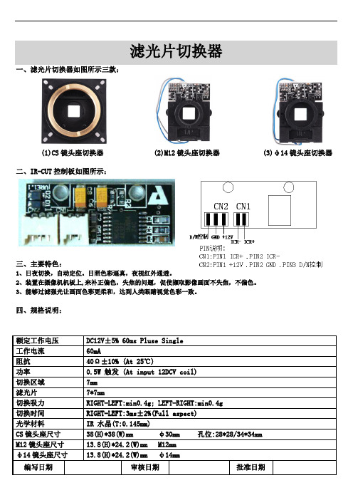
一、滤光片切换器如图所示三款:
(1)CS镜头座切换器(2)M12镜头座切换器(3)φ14镜头座切换器
二、IR-CUT控制板如图所示:
三、主要特色:
1、日夜切换,自动定位。日照色彩逼真,夜视红外通透。
2、装置在摄像机机板上,来补正偏色,失焦的问题,促使撷取影像画面不失焦,不偏色。
3、能够过滤强光让画面色彩更柔和,达到人类眼睛视觉色彩一致。
切换时间
RIGHT-LEFT:3ms±2%(Full aspect)
光学材料
IR水晶(T:0.145mm)
CS镜头座尺寸
38(H)*38(W)mmφ30mm孔位:28*28/34*34mm
M12镜头座尺寸
13.8(H)*24.2(W)mmM12mm
φ14镜头座尺寸
13.8(H)*24.2(W)mmφ14mm
四、规格说明:
额定工作电压
DC12V±5% 60ms Pluse Single
工作电流
60mA
阻抗
40Ω±10% (At25℃)
功率
0.5W触发(At input 12DCV coil)
切换区域
7mm
滤光片
7EFT:min0.4g; LEFT-RIGHT:min0.4g
达拉电子200W热电转换器说明书
Specification For ApprovalCustomer :Description : Thermoelectric cooler 200WCustomer part no : Rev. :Delta model no : HET200PC Rev. : 05 Sample issue no :Sample issue date : Aug.5 2020Please send one copy of this specification back after yousigned approval for production pre-arrangementApproved by :Date :DELTA ELECTRONICS, INC.252, SHANG YING ROAD, KUEI SAN TEL : 886-(03)-3591968 TAOYUAN HSIEN 333, TAIWAN, R. O. C. FAX : 886-(03)-3591991Table of contentModify the airflow & Certified safety (13)1.Description (4)1-1. General description : (4)1-2. Main feature (Operating 48VDC at 25゚C) (4)1-3. Dimension (5)1-3-1 Drawing (5)1-3-2 Mounting panel cutout (6)1-4. Maintenance (7)1-5. Thermal path and airflow baffle (7)2.Electrical specification (8)2-1. Indicator & connector (8)2-2. Cooling Performance VS Temperature Difference (8)2-3. TEC work temperature range (8)2-4. Interface (9)3.Environmental conditions (11)3-1. Operating temperature : (11)3-2. Storage temperature : (11)3-3. Humidity (11)3-4. Protection rating (11)3-5. MTBF (11)4.Certified safety (12)4-1. Safety Mark (12)er cable (12)5-1Power cable (12)Specification for approvalCustomer :Description : Thermoelectric cooler 200WCustomer P/N : Rev. :Delta model no. : HET200PC Rev. : 03 Sample revision: Issue no. : Sample issue date : Quantity : sets1. Description1-1. General description :The Thermoelectric cooler (TEC) is designed for direct air to air heat removal in the cabinet. It is easy to be installed in the cabinet(recommended on the door of the cabinet) with the nuts.The internal and external air circulation loops of the TEC Module are separated to prevent the entry of dust, humidity and dirt. The unit conforms to IP55 protection rating on the external air circuit.1-2. Main feature (Operating 48VDC at 25゚C)*200 W cooling capacity is defined at △T=0℃and Tambient =25℃*The cooling capacity is defined when the internal and external airflow rate are at 100 CFM and 120 CFM, accordingly.*Cooling capacity is for internal side.1-3. Dimension1-3-1 Drawing(1) Material : case aluminum sheet , t=1.5mm(2) Finish : Power paint 75~120um,(3) Color : RAL 7032(4) Dimension tolerance:X.X [X.XX] : ± 1.0mm [0.04”]X.XX [X.XXX] : ± 0.3mm [0.012”]1-3-2 Mounting panel cutout1-4. Maintenance1-4-1. Be sure to disconnect power supply before disassembly TEC module from customer cabinet.1-4-2. Please refer to Delta authorized engineers for TEC module component replacement service, no allow unauthorized personnelto repair the unit.1-4-3. If the replacement by user himself is necessary, please refer to the exploded drawing shown as previous page and below descriptionfor disassembly.External fan: Disassemble mounting screw of external fan via screwdriver & pull out the connector.Internal fan: Disassemble mounting screw of internal fan via screwDriver & pull out the connector.Controller: Need to disassemble internal fan first , then pull-out all cable connection on controller , take off mounting screw of controllerfinally .TEC device: Due to TEC device have waterproof sealant protection and thermal conductive compound with heat-sink, please kindlyship back to Delta for replacement.1-5. Thermal path and airflow baffleThe thermal exchange path is shown in the figure below.2. Electrical specification2-1. Indicator & connectorConnector " -48V VDC " mate with JWT C4201WR0-2*3PNL 2-2. Cooling Performance VS Temperature Difference2-3. TEC work temperature rangeHET200PC has two work status, cooling and heating, according to the cabinet internal temperature (detect by on-board NTC).2-4. InterfaceHET200PC control-board interface is as diagram. The function will be described as following:LED and Test Button:LED "STATUS"(Green) : HET200PC work in cooling mode(Red) : HET200PC work in heating mode(Dark): HET200PC TEC function OFF(Blink red) : Sensor failed⏹LED "TEC" *(Green) : TEC normal(Red) : TEC failed(Blink green) : TEC normal in test process(Blink red) : TEC failed in test process⏹LED "FAN"(Green) : Fan normal(Red) : Fan failed(Blink Green) : Fan normal in test process(Blink Red) : Fan failed in test process⏹TESTThere is an auto test button on HET200PC, user can press this button to run heating and cooling process, the process is about 3~4 mints. User can turn off this function by pressing this button again.Alarm dry contact: (MAX. 60VDC 400mA or 125VAC, 400mA)⏹Pin1 to pin3 “Close”:Normal⏹Pin1 to pin3 “Open”:Fan, TEC or sensor failed⏹Pin2 to pin3 “Open”:Normal⏹Pin2 to pin3 “Close”:Fan, TEC or sensor failed3. Environmental conditions3-1. Operating temperature :-40°C ~ +55°C (-40°F ~ 131°F)3-2. Storage temperature :-40°C ~ +65°C (-40°F ~ 149°F)3-3. HumidityExternal air circuit: 0 ~ 100% RHInternal air circuit: 0 ~ 90% RH3-4. Protection ratingIP55 (IEC60529) on external side with mounting on door.GR487 salt fog test complied on external side3-5. MTBFFan lifetime is expected to have a minimum L10 life of 80,000 hours continuous operation at 40°C with 15 ~ 65%RH at 48 voltage4. Certified safety4-1. Safety Mark5. User cableEach HET200PC will provide 1 cable with shipment.5-1 P ower cable。
HVA200高压放大器操作手册说明书
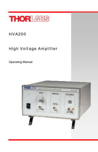
High Voltage AmplifierOperating ManualTable of ContentsPart 1.Important Safety Notice (3)Part 2.Product Overview (4)Part 3.Setup and Operation (5)3.1.HVA200 Controls and Features (7)Part 4.HVA200 Specifications (8)Part 5.Maintenance (10)5.1.Fuse Replacement (10)5.2.Ventilation (10)5.3.Troubleshooting (10)Part 6.Warranty Information (11)Part 7.Declaration of Conformity (12)Part 8.Regulatory (13)Part 9.Thorlabs Worldwide Contacts (14)Table of FiguresFigure 1:HVA200 Front Panel Features (7)Figure 2:HVA200 Rear Panel Features (7)Figure 3:Typical Gain Bandwidth (9)Part 1. Important Safety NoticeDanger High VoltageThe HVA200 can produce hazardous voltages andcurrents which may be harmful or even lethal. Usecaution and exercise preventative safety measuresto prevent contact between these high voltages andany personnel.Warning!The line switch and fuse must be set to the correctmains voltage. The unit is shipped ready tooperate on 115 V. To operate on 230 V, the lineswitch and fuse must be changed. See Section 5.1:Fuse Replacement.Do Not Open Housing!The HVA200 has no user-serviceable parts. Service should only beperformed by trained service personnel.Part 2. Product OverviewThe Thorlabs HVA200 High Voltage Amplifier is designed to directly drive the Thorlabs Electro-Optic Modulators. The amplifier features: a large, ±200 V output, a continuous current output of 100 mA, a wide, 1 MHz bandwidth, and low noise. The voltage gain of -20 boosts the input up to the high voltages needed to drive our lithium niobate broadband modulators. An adjustable bias allows for precise DC offset control.The HVA200 uses a high voltage, wideband, high slew rate output amplifier to achieve an output range of ±200 V at a bandwidth up to 1 MHz. The input amplifier includes a summing junction which allows an adjustable DC bias to be added to the input modulation. This composite signal is then boosted by a fixed voltage gain of 20 by the output amplifier. For added safety, a front panel HV Enable button must be pressed to connect the HV output to the output BNC. The output is automatically disabled each time the HVA200 is powered on.The DC Bias control consists of a rotary encoder which allows precise control and repeatability. The bias adjustment is typically used to shift the DC level of the output as needed by the application.A voltage monitor output is provided to allow real-time monitoring of the high voltage output. The monitor has a scaling of 20:1 so that an output of 200 V results in a 10 V monitor voltage.Part 3. Setup and Operation WarningBefore plugging the amplifier into an AC outlet, check that the lineswitch voltage matches your AC outlet. The amplifier is configuredfrom the factory to operate on 115 V by default. The fuse and lineswitch will need to be changed for 230V operation. See Section 5.1:Fuse Replacement.To setup the unit, refer to Figures 1 and 2, and the legend table on the preceding page andperform the following steps:1. See the warning above. Attach the supplied AC power cord to the ACconnector on the rear panel and plug into a suitable AC outlet.2. Connect an EO-modulator to the HV Output connector (6) on the front panel. HV Output Warning The HV output is capable of producing hazardous voltages andcurrents. The HV output will handle an accidental short circuitwithout damage, but the output should not be shortedcontinuously. The current is internally limited to 100 mA.3. (Optional) Connect the HV monitor (4) to an oscilloscope or volt meter. Theinput impedance must be at least 50Ω; however, at this value the ratio will be40:1. The true HV Output to monitor ratio can be calculated with the followingequation:()inputinput monitor out R R V V Ω+=5020Where:V out is the HV outputV monitor is the HV Monitor outputR input is the input impedance of the measurement deviceFor impedance values of 50Ω, the equation becomes:monitor out V V 40=For impedance values of greater than 10 k Ω, the internal impedance isinsignificant and the equation becomes:monitor out V V 20=The HV Output Monitor requires a minimum load of 50Ω. Theport will handle an accidental short circuit without damage, butmust not be shorted for more than 5 sec to prevent excessive heating of the output resistor. The output will source up to 200mAwhen a short circuit is applied.4.If a modulating signal is to be used, connect it to the Modulation Inputconnector (2) on the front panel. This signal will be amplified by a fixedvoltage gain of -20.5.Turn the power switch (1) on. At this point the amplifier is powered up but theHV Output is disabled. The power indicator should be illuminated. If not,check the AC fuse (see page 10). Confirm that the HV Enable LED (5) is off.6.After confirming that all connections are correct, the amplifier output can beenabled by pressing the HV Enable button on the front panel (5).7.Adjust the amplitude of the modulation signal as needed.8.The DC level of the output can be shifted by adjusting the DC Bias Adjustcontrol (3).Legend Table for Facing PageLegend Description1 Main Power Switch2 Modulation Input Signal - BNC3 DC Bias Adjust Knob & Indicator Dial4 HV Output Monitor - BNC5 HV Enable Button6 HV Output – BNC (DANGER, High Voltage)7 AC Input Connector – IEC and Fuse Drawer8 CoolingFan9 Line Voltage Selector Switch3.1. HVA200 Controls and FeaturesFigure 1: HVA200 Front Panel FeaturesFigure 2: HVA200 Rear Panel FeaturesPart 4. HVA200 SpecificationsSpecification DescriptionPhysical FeaturesInput Connector BNC (± 10V, 10 mA)HV Output Connector2 BNC (± 200V, 100 mA)HV Monitor Connector3 BNC (± 10V, 200 mA, Min Load 50 Ω)Bias Adjustment Digital EncoderOutput Enable Front Panel PushbuttonOutput HV Indicator Bright LEDPower Switch Rocker SwitchDimensions 9″ x 5″ x 12.5″228.6 mm x 127 mm x 317.5 mmlbs Weight 11.6 Other Tilting Rubber-Padded FeetMax Ratings:Max Output Current 100 mA DCMax Input Voltage Range -10 to 10 VFuse Rating 630 mA @ 115 VAC (5x20 mm SLO-BLO)400 mA @ 230 VAC (5x20 mm SLO-BLO)Operating Temperature Range 10 to 40°C, MAX 85% RHElectrical CharacteristicsMax. Input Voltage Range -10 to 10 VInput Impedance 1 kΩOutput Voltage -200 to 200 VOutput Impedance 50ΩSlew Rate 400 V/μsOutput Noise 1.5 mV RMSVoltage Gain1-20 ± 2%DC Bias Adjust -200 to 200 VHV Monitor to Output Ratio:With Input Impedance of 50Ω40:1 (Vout / 40 ± 6%)With Input Impedance of >10 kΩ20:1 (Vout / 20 ± 6%)HV Monitor Output Impedance 50ΩAC Power 115V/230V, 50-60 Hz, 70 VA1 The voltage gain is inverted to preserve the high slew rate of the output amplifier (i.e., a -1 V input results in+20 V output).2 The HV output will handle an accidental short circuit without damage, but the output should not be shortedcontinuously.3 The HV monitor output will handle accidental short circuits without damage, but must not be shorted for morethan 5 sec to prevent excessive heating of the output resistor. The HV monitor output will source up to 200 mAwhen a short circuit is applied.Figure 3: Typical Gain BandwidthTypical Gain Bandwidth 151821242710100100010000100000100000010000000Frequency (Hz)Voltage Gain(dB)Part 5. MaintenanceThe HVA200 amplifier needs very little maintenance under normal operating conditions. There are no serviceable parts in the HVA200. The enclosure may be cleaned by wiping with a soft damp cloth. If you suspect a problem with your HVA200 please call Thorlabs and technical support will be happy to assist you.5.1. FuseReplacementThe AC input is protected by a fuse located in a pull out compartment drawer on the rear panel AC connector. Refer to Figure 2 on page 7. If replacement is needed, disconnect the power cord from the back of the amplifier and pull the fuse compartment drawer out to expose the fuse. A small screwdriver may be used to pry the drawer open.Replace the fuse with the correct rating. Do not use a fuse with a current rating higher than the unit is rated for. The fuse ratings are as follows:•115V: 630 mA 5x20mm SLO-BLO•230V: 400 mA 5x20mm SLO-BLO5.2. VentilationFor proper operation and protection of the output amplifier, it is important that the ventilation passages located on the sides and rear of the unit not be obstructed from free airflow.5.3. TroubleshootingProblem Solutions“PWR ON” not illuminating, unit is notfunctioningCheck that the power switch in the on position, the mains connection is correct, and the fuse has not been damaged.Output will not enable, “OUTPUT ON” isflashingThe amplifier has gone into a protection mode because the circuitry has sensed that one of the HV supplies is not workingcorrectly.Part 6. Warranty InformationGeneral Product WarrantyThorlabs warrants that all products sold will be free from defects in material and workmanship, and will conform to the published specifications under normal use and service when correctly installed and maintained.Opto-MechanicsLifetime Warranty: Thorlabs offers a lifetime warranty on all opto-mechanical components. Thorlabs will repair or replace any opto-mechanical product which after evaluation has failed to perform in the above conditions.Optical Tables and BreadboardsLifetime Warranty: We provide a lifetime guarantee that all of our passively damped optical tables and breadboards will meet all originally stated performance specifications under normal use and proper handling. We additionally guarantee that all our table tops and breadboards, both active and passive, will be free from defects in workmanship, including de-lamination of the skins under normal use and handling.Lasers and Imaging SystemsThorlabs offers a one year warranty on all lasers and imaging systems, with the exceptions of laser diodes. Some products are warranted for the number of hours specified in the operating manual of each laser.Opto-Electronics, Control Electronics, Optics, and Nano-Positioning Product Lines Thorlabs offers a two year warranty on the above mentioned product lines, provided normal use and maintenance of the products and when properly handled and correctly installed. Thorlabs shall repair or replace any defective or nonconforming product as detailed above. We ask that buyer contact Thorlabs for a Return Material Authorization number (RMA #) from our Customer Service/Returns department in order to most efficiently process the return and/or repair.Products returned for repair that are not covered under warranty, a Thorlabs standard repair charge shall be applicable in addition to all shipping expenses. This repair charge will be quoted to the customer before the work is performed.Warranty ExclusionsThe stated warranty does not apply to Products which are (a) specials, modifications, or customized items (including custom patch cables) meeting the specifications you provide;(b) ESD sensitive items whose static protection packaging has been opened; (c) items repaired, modified or altered by any party other than Thorlabs; (d) items used in conjunction with equipment not provided by, or acknowledged as compatible by, Thorlabs; (e) subjected to unusual physical, thermal, or electrical stress; (f) damaged due to improper installation, misuse, abuse, or storage; (g) damaged due to accident or negligence in use, storage, transportation or handling.Part 7. Declaration of ConformityPart 8. RegulatoryAs required by the WEEE (Waste Electrical and Electronic Equipment Directive) of theEuropean Community and the corresponding national laws, Thorlabs offers all end users in the EC the possibility to return “end of life” units without incurring disposal charges.•This offer is valid for Thorlabs electrical and electronic equipment:•Sold after August 13, 2005•Marked correspondingly with the crossed out“wheelie bin” logo (see right)•Sold to a company or institute within the EC•Currently owned by a company or institute withinthe EC•Still complete, not disassembled and notcontaminatedAs the WEEE directive applies to self contained operationalWheelie Bin Logo electrical and electronic products, this end of life take backservice does not refer to other Thorlabs products, such as:•Pure OEM products, that means assemblies to be built into a unit by the user(e.g. OEM laser driver cards)•Components•Mechanics and optics•Left over parts of units disassembled by the user (PCB’s, housings etc.).If you wish to return a Thorlabs unit for waste recovery, please contact Thorlabs or your nearest dealer for further information.8.1. Waste Treatment is Your Own ResponsibilityIf you do not return an “end of life” unit to Thorlabs, you must hand it to a company specialized in waste recovery. Do not dispose of the unit in a litter bin or at a public waste disposal site.8.2. EcologicalBackgroundIt is well known that WEEE pollutes the environment by releasing toxic products during decomposition. The aim of the European RoHS directive is to reduce the content of toxic substances in electronic products in the future.The intent of the WEEE directive is to enforce the recycling of WEEE. A controlled recycling of end of live products will thereby avoid negative impacts on the environment.Part 9. Thorlabs Worldwide Contacts USA, Canada, and South AmericaThorlabs, Inc.435 Route 206Newton, NJ 07860USATel: 973-579-7227Fax: 973-300-3600email:*********************EuropeThorlabs GmbHHans-Böckler-Str. 685221 DachauGermanyTel: +49-(0)8131-5956-0 Fax: +49-(0)8131-5956-99 email:*******************UK and IrelandThorlabs LTD.1 Saint Thomas Place, Ely Cambridgeshire CB7 4EX Great BritainTel: +44 (0)1353-654440 Fax: +44 (0)1353-654444 email:*********************Japan and AsiaThorlabs Japan Inc.5-17-1, OhtsukaBunkyo-ku, Tokyo 112-0012 JapanTel: +81-3-5977-8401 Fax: +81-3-5977-8402 www.thorlabs.jpemail:*****************ScandinaviaThorlabs Sweden ABBox 141 94400 20 GöteborgSwedenTel: +46-31-733-30-00Fax: +46-31-703-40-45email:************************Thorlabs, Inc.435 Route 206NNewton, NJ 07860 USAPhone: (973) 579-7227 ♦ Fax: (973) 300-3600 。
Ikan Stryder 200 Watt LED 双色灯光说明书

******************** © 2017 ikan Corporation. All rights Reserved713.272.8822What’s Included1 x SB200 Light Fixture 1 x Barn Doors1 x Power Supply with Cable1 x Yoke 1 x V-Mount Battery Plate 1 x Gold Mount Battery PlateSB200Stryder 200 Watt LED Bi-Color LightGetting StartedThank you for buying the Stryder Portable LED Fresnel Spotlight from Ikan. Please carefully read the instructions and guide before operating the products. The guide includes product usage and maintenance. When you operate the product, please make sure that you have read the instructions carefully.All the content of the manual is based on up-to-date information; technical data subject to change without notice.Safety Instructions:1. Connect the power supply to the 15VDC Connector on the SB200 Light before plugging into the power source. You risk electrocution by not following the instruction.2. Don’t drag cables with excessive force. Any repairs on the products should be performed by Ikan technicians. Users should not remove the power supply, or else the damage will not be covered under warranty.3. Confirm that the power is off before connecting and changing the fixture head or disconnecting your cable from the power source. We recommend using Ikan customized connecting cables and connectors to avoid electrical shock.4. The voltage shouldn’t exceed the value in the technical specifications. If the voltage is greater than, or less than the regulated values, it could damage the product.OverviewBenchmark color temperatures for today’s TV production are 5600K (daylight) and 3200K (tungsten). Ikan developed the SB-200 Spotlight to handle both these temperatures. With patented technologies, the SB200 offers a professional and customizable LED light source. In addition, the light features separately-cooling ducts for optimizing heat dissipation. Specifically, the SB-200 Spotlight offers the following features:1. The 0-100% brightness incremental adjustment of the 2700K-5600K temperature enable fine-tuning your color range.2. A 7-inch diameter Fresnel lens provides even, well-distributed light at a 60 degree beam angle.3. Fresnel Spot adaptor allows the Beam to be reduced to a 30 degree spot.4. Ultra-low noise and active cooling technology contribute to excellent thermal stability.5. The power supply will automatically cut off when the fixture overheats.6. The bright LCD readout is easy to view, enabling smooth adjustment of functions.7. Digitally adjustable knob allows you to adjust menu settings quickly and accurately.8. AC/DC power supply, AC110VAC-270VAC, DC 15V .Instructions:LED spotlight’s housing is made of fiber reinforced plastic which is heavy-duty, lightweight, flexible and easy to transport/ The SB200 structure is illustrated as follows:What’s in the Box?Please carry and place the packing box carefully. Check the lighting equipment and accessories upon opening the box. Please contact us if anything is damaged or missing. Please save the packing materials for replacing and repairing the products in the future.What’s Included:SB200 Light FixturePower Supply with Cable Barn Doors Yoke MountAppearance & Structure - Front5/8" Receiver: Connecting the lamp with standsYoke: Adjustable lighting directionAdjustable Beam Limiter: It allows the light to move from a 60° beam angle to a 30° beam angleCarry Handle: Top grip handle for easy grab and go lightingAppearance & Structure - BackPower Switch: Turn ON/OFF Power under the fixtureLCD Settings: Displays brightness & color temperatureLarge Yellow Knob: Allows for adjustment of brightness & color temperatureFour Adjustment Buttons: ON/OFF-A, Menu-M, Advanced-B, Enter-EGrip Handles: For making adjustments while the light is on the standPower ButtonAdjustment ButtonsLarge Y ellow Knob LCD ScreenGrip HandleY okeAdjustable Beam LimiterBarn DoorsCarry Handle5/8" Receiver5/8" ReceiverSpecificationsOptional AccessoriesSome other products that work well with the Stryder Light available from Ikan include:HD-STND-V2KCP-703ROLLR-STND10SW-04IDX-096Heavy Duty Light Stand Stage Clamp with 16mm Stud 2-Stage Roller Stand 10 ft 6 in.Safety Wire 96 Channel DMX ConsoleInstallation & Power Supply1. Ensure power is OFF before installation.2. Place the light on the Ikan stands, release the tension knob on the 5/8” receiver, adjust the light in the desired direction, and tighten the tension knob on the 5/8” receiver.3. When connecting the power cords, plug the DC power cords into the socket on the rear panel (as shown on the drawing). If batteries are used: Illuminate light by pressing power switch. On the default screen the number 13.8V at the upper right corner indicated the current internal DC voltage. When powered by the battery it means the current battery voltage; however, this number will display in flashing status if the voltage is lower than 11V which indicates low battery voltage.Power the LEDsThe SB200 light comes with an included AC power supply and 4 ft cable. This allows the user to plug into any standard 120-240 VAC electrical outlet. The SB200 light can be powered from either an AB Mount Pro Battery, or a V-Mount Battery. The fixture comesstandard with either AB-Mount or V-Mount plates.DMX 512 ControlsThe DMX IN/OUT on the SB-200 allows for remote fixture control over thecolor and brightness.The 8Bit DMX allows for use with controllers that use just dimmer controls.Depending on channel assigned the brightness is controlled on the firstfader. The next fader controls the color temperature from 2700K at 0% to6500K at 100%.Learn MoreMore dynamic information at official website: SupportContactemail:********************CONDITIONS OF WARRANTY SERVICE• Free service for one year from the day of purchase if the problem is caused by manufacturing errors.• The components and maintenance service fee will be charged if the warranty period is expired.Free Service will not be Provided in the Following Situations:(*Even if the product is still within the warranty period.)• Damage caused by abuse or misuse, dismantling, or changes to the product not made by the company.• Damage caused by natural disaster, abnormal voltage, and environmental factors, etc.©2017 ikan Corporation. All rights reserved。
双滤光片切换器(ircut) 测试板说明书
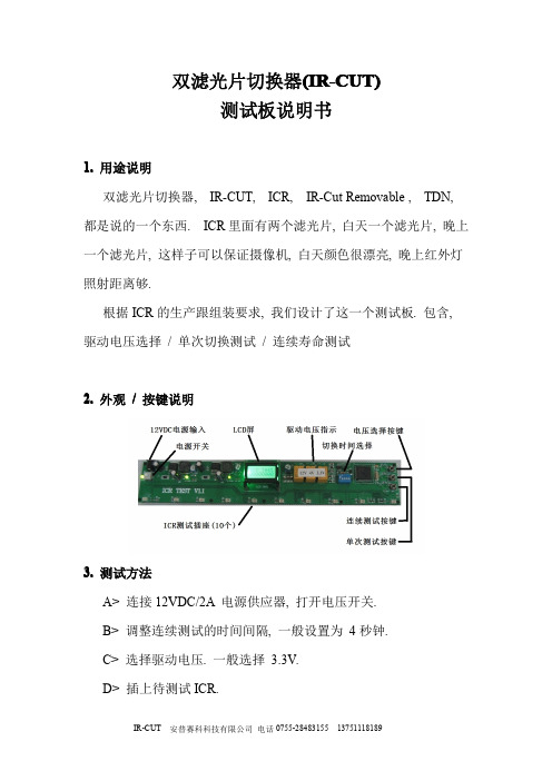
双滤光片切换器(IR-CUT)测试板说明书1.用途说明双滤光片切换器,IR-CUT,ICR,IR-Cut Removable,TDN,都是说的一个东西.ICR里面有两个滤光片,白天一个滤光片,晚上一个滤光片,这样子可以保证摄像机,白天颜色很漂亮,晚上红外灯照射距离够.根据ICR的生产跟组装要求,我们设计了这一个测试板.包含,驱动电压选择/单次切换测试/连续寿命测试2.外观/按键说明3.测试方法A>连接12VDC/2A电源供应器,打开电压开关.B>调整连续测试的时间间隔,一般设置为4秒钟.C>选择驱动电压.一般选择3.3V.D>插上待测试ICR.E>按单次测试按键或是连续测试按键.4.单次性能测试一般用低电压3.3V测试ICR切换器的摩擦力性能,如果3.3V可以推动ICR,表示内部摩擦力小,性能通过.用4V测试是因为一些网络摄像机是5VDC供电,扣掉驱动芯片的电压,实际作用在ICR上面的电压是4VDC.对于网络摄像机用的ICR应该要通过4V的测试电压.用高电压12VDC测试ICR切换器的耐受力,安防摄像机电压是12VDC,ICR必须经受的起12VDC才可以.按一下单次测试按键,ICR切换一次,在切换的过程中观察滤光片的切换是否顺畅.同时把ICR移动不同位置,观察在各种位置是否都可以切换.5.寿命测试ICR的内部机械结构,是否能够承受长时间的切换,我们设计了寿命测试模式.把驱动电压调整到12V,测试时间间隔调整到4秒钟,然后按连续测试按键,这时候LCD屏的计数器开始计数,每隔4秒钟,ICR切换一次,10万次的测试时间大概是3天3夜左右.在寿命测试的过程中,每间隔几个小时观察一下,是不是10个ICR都正常.测试到达10万次的时候,测试板会自动停下来.测试完成以后,要把电压切换到3.3V测试一下摩擦力有没有问题.。
- 1、下载文档前请自行甄别文档内容的完整性,平台不提供额外的编辑、内容补充、找答案等附加服务。
- 2、"仅部分预览"的文档,不可在线预览部分如存在完整性等问题,可反馈申请退款(可完整预览的文档不适用该条件!)。
- 3、如文档侵犯您的权益,请联系客服反馈,我们会尽快为您处理(人工客服工作时间:9:00-18:30)。
深圳市志远科技有限公司
200万高清电磁阀式日夜切换器
承认书
贵司承认意见栏:
检印:
20100-6-6
发行发行日期:201
承认检印作成
李静※注意:签订『保密或采购契约』后再使用本数据。
备注:1.本内容有必要变更时请与敝公司人员联络。
2.本资料拥有著作权及专业技术,故仅能用于本制品内不可他用,且不可
复写(印),或提供给第三者使用(其它公司)。
3.因系样品制品内容有变更时不再通知请见谅。
4.【】数值变动可能、量产规格内容另作说明。
5.本规格书附件一为IR_Cut光谱图。
格书
名版本
V1.1
型号
ZH ZHM
M 12A-20-2.51.应用范围
本规格书列表产品为IR 与AR 光波段之开关模块,英文称为IR Cut module 于CCTV 监视镜头与室外摄像设备适用之。
本规格书提供给生产摄像机之客户使用,不另作其他用途。
2.一般规格
表列规格一般特性检测值是在环境温度25℃,相对湿度60%±15%下测得之数据,对于特殊应用规格需另订之。
本产品组成之原物料件皆符合Rohs 订定规范(Rohs 规范以SGS 国家质检局发布为基准)。
本产品之光波段定义于400~1000LUX 置25~35cm 量测距离订列所有相关规格值。
产品之结构外观尺寸如外观尺寸图所示。
本产品所使用的IR Cut 之玻璃光学特性,规格如附件一。
本产品主要组成组件为电磁阀控体带动带玻片使滤光玻片达到切换的能力。
3.作动状态
3.1一般作动
利用脉波触发电路控制电磁阀控体控制滤光片的切换。
3.2一般常态
本产品处于一般静止状态下,是无耗电电流。
3.3光圈位置
机构在未激发状态下,滤光片仍具有保持位置的能力
格书
名版本
V1.1
型号
ZH ZHM
M 12A-20-2.55.引出线定义5.1引出线规格
Connect Cable :UL 1571Awg 30Connector :51021-0200Pitch :P =1.25Pin :50058-80005.2引出线尺寸:
6.玻璃规格
SPECIFICATION ~VCC
IR 红玻
400~580nm ,Ta 90%以上645nm ±15nm ,Ta 50%±5750~1050nm ,Ta 3%以下1050~1100nm ,Ta 5%以下AR 白玻
全通率99%以上
7.外观
7.1表面处理铁盖板使用合金铝染黑,外观不可脱漆、落皮。
7.2镀锡规格本产品均采用无铅制程,锡条规格为PF610-0.6。
7.3制造日期见包装箱体标签处。
IR CUT DRIVER FUNCTION
Trig 1(红线)Trig 2(黑线)光径状态VCC Vdc 0V IR 0V VCC Vdc AR
格书
名版本
V1.1
型号
ZH ZHM
M 12A-20-2.58.图一
IRCUT 尺寸图
格书
名版本
V1.1
型号
ZH ZHM
M 12A-20-2.5图二
产品外观尺寸图
格书
名版本
V1.1
型号
ZH ZHM
M 12A-20-2.59.包装方式
本产品捆包使用Tray 盘单体包装,一盘Tray 盘7Pcs 为一排共5排计35Pcs 一盘,(如图一所表),然后10盘Tray 盘为一箱计350Pcs (如图二所表)。
格书
名版本
V1.1
型号
ZH ZHM
M 12A-20-2.510.附IR 光谱图。