inter2C说明书
ARGOX CP 系列使用手冊说明书
C OMPACT P RINTER 系列CP-2140 / CP-2140Z CP2140M/CP-2140MZ CP-3140L / CP-3140ZL使用手冊目錄1.簡介 (4)專屬聲明 (4)產品改良 (4)賠償聲明 (4)2.開始使用 (5)打開印表機包裝 (5)包裝內容物 (6)印表機概述 (7)前視圖: (7)後視圖:CP-2140、CP-2140Z、CP-3140L、CP-3140ZL (8)(CP-2140M,CP-2140MZ 無RS-232、並列埠) (8)內部檢視I (9)內部檢視II (10)連接電源 (11)裝入紙張 (12)準備紙張 (12)裝入紙捲 (12)紙張感應器設定 (17)由軟體/驅動程式設定並排標籤 (17)手動設定並排標籤 (18)裝入碳帶 (23)準備碳帶 (23)裝入碳帶捲 (24)3. 印表機操作 (30)列印紙校正及設定 (30)開始進行紙張校正及設定的步驟 (30)印表機組態標籤範例 (31)將印表機重設為原廠預設值 (32)從LED 指示燈診斷進行疑難排解 (37)其他 (40)恢復程序 (41)4. 通訊 (42)介面和需求 (42)USB 介面需求 (42)串列埠(RS-232) 介面需求 (43)並列埠(Parallel) 介面需求 (43)連接需求 (43)印表機通訊 (45)安裝隨插即用驅動程式(僅適用於USB) (45)安裝印表機驅動程式(適用於USB以外的其他介面) (50)5. 維護印表機 (57)印字頭維護指南 (57)清潔週期 (57)清潔材料 (57)清潔方向 (58)6. 產品規格 (59)一般規格 (59)字型、條碼和圖形規格 (61)Printer Programming Language PPLA (61)Printer Programming Language PPLB (62)Printer Programming Language PPLZ (63)介面規格 (64)USB介面 (64)串列介面 (65)並列介面 (66)7. 附錄 (69)安裝旋刀/ 閘刀裁紙器 (69)設定旋刀/ 閘刀裁紙器 (73)旋刀裁紙器卡紙排除 (76)閘刀裁紙器卡紙排除 (77)1. 簡介專屬聲明本手冊包含立象科技股份有限公司擁有之專屬資訊。
N321温控器使用说明书
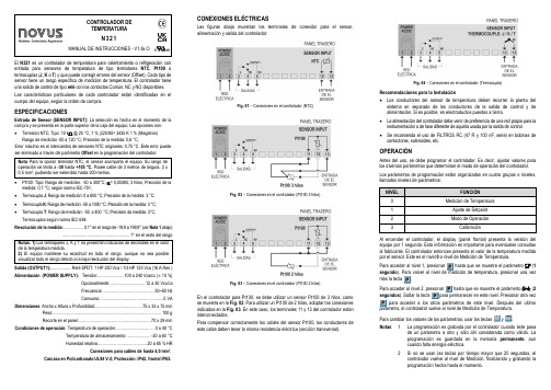
CONTROLADOR DE TEMPERATURAN321MANUAL DE INSTRUCCIONES - V1.8x OEl N321 es un controlador de temperatura para calentamiento o refrigeración con entrada para sensores de temperatura de tipo termistores NTC , Pt100 o termocuplas (J, K o T ) y que puede corregir errores del sensor (Offset). Cada tipo de sensor tiene un rango específico de medición de temperatura. El controlador tiene una salida de control de tipo relé con los contactos Común, NC y NO disponibles. Las características particulares de cada controlador están identificadas en el cuerpo del equipo, según la orden de compra.ESPECIFICACIONESEntrada de Sensor (SENSOR INPUT): La selección es hecha en el momento de la compra y se presenta en la parte superior de la caja del equipo. Las opciones son: • Termistor NTC; Tipo: 10 k Ω @ 25 °C, 1 %, β25/85= 3435 K 1 % (Megatron)Rango de medición -50 a 120 °C; Precisión de la medida: 0,6 °C; Error máximo en el intercambio de sensores NTC originales: 0,75 °C. Este error puede ser eliminado a través del parámetro Offset en la programación del controlador. Nota : Para la opción termistor NTC, el sensor acompaña el equipo. Su rango de operación se limita a -30 hasta +105 °C. Posee cable de 3 m etros de largura, 2 x 0,5 mm², pudiendo ser extendido hasta 200 metros.• Pt100: Tipo: Rango de medición: -50 a 300°C; α= 0,00385; 3 hilos; Precisión de la medida: 0,7 °C; según norma IEC-751; • Termocupla J : Rango de medición: 0 a 600 °C; Precisión de la medida: 3 °C; • Termocupla K : Rango de medición: -50 a 1000 °C; Precisión de la medida: 3 °C; • Termocupla T : Rango de medición: -50 a 400 °C; Precisión da medida: 3°C;Termocuplas según norma IEC-584.Resolución de la medida: ................. 0,1° en el rango de -19,9 a 199,9° (ver Nota 1 abajo)......................................................... 1° en el resto del rango Notas: 1) Los termopares J, K y T no presentan indicación de decimales en el valor de la temperatura medida.2) El equipo mantiene su exactitud en todo el rango, aunque no sea posible visualizar todo el rango debido a la baja resolución del display.Salida (OUTPUT1): .................. R elé SPDT; 1 HP 250 Vc a / 1/3 HP 125 V ca (16 A Res.) Alimentación (POWER SUPPLY): Tensión: ...................... 100 a 240 V c a/c c (± 10 %)Opcionalmente: ............................. 12 a 30 Vc c /ca Frecuencia: ........................................... 50~60 Hz Consumo: ......................................................5 VADimensiones : Ancho x Altura x Profundidad: ........................................ 75 x 33 x 75 mmPeso:............................................................................................ 100 g Recorte en el panel: ............................................................. 70 x 29 mmCondiciones de operación: Temperatura de operación: ................................ 0 a 40 °CTemperatura de almacenamiento: .................... -20 a 60 °C Humedad relativa: ......................................... 20 a 85 % HRConexiones para cables de hasta 4,0 mm².Carcasa en Policarbonato UL94 V-2; Protección: IP42, frontal IP65.CONEXIONES ELÉCTRICASLas figuras abajo muestran los terminales de conexión para el sensor, alimentación y salida del controlador:Fig. 01 – Conexiones en el controlador (NTC)Fig. 02 – Conexiones en el controlador (Pt100 3 hilos)Fig. 03 – Conexiones en el controlador (Pt100 2 hilos)En el controlador para Pt100, se debe utilizar un sensor Pt100 de 3 hilos, como se muestra en la Fig. 02. Para utilizar un Pt100 de 2 hilos, adoptar las conexiones indicadas en la Fig. 03. En este caso, los terminales 11 y 13 del controlador están interconectados.Para compensar correctamente los cables del sensor Pt100, los conductores de este cable deben tener la misma resistencia eléctrica (sección transversal).Fig. 04 – Conexiones en el controlador (Termocupla)Recomendaciones para la Instalación• Los conductores del sensor de temperatura deben recorrer la planta del sistema en separado de los conductores de la salida de control y de alimentación. Si es posible, en electroductos puestos a tierra. • La alimentación del controlador debe venir de preferencia de una red propia para la instrumentación o de fase diferente de aquella usada por la salida de control. • Se recomienda el uso de FILTROS RC (47 R y 100 nF, serie) en bobinas de contactoras, solenoides, etc.OPERACIÓNAntes del uso, se debe programar el controlador. Es decir, ajustar valores paralos diversos parámetros que determinan el modo de operación del controlador. Los parámetros de programación están organizados en cuatro grupos o niveles, llamados niveles de parámetros:NIVELFUNCIÓN 0Medición de Temperatura 1Ajuste de Setpoint 2Modo de Operación3CalibraciónAl encender el controlador, el display (panel frontal) presenta la versión del equipo por 1 segundo. Esta información es importante para eventuales consultas al fabricante. El controlador entonces presenta el valor de la temperatura medida por el sensor. Este es el nivel 0 o nivel de Medición de Temperatura.SP (1 segundopresionar una vezunt (2 Para cambiar los valores de los parámetros, usar las teclas y .Notas : 1 La programación es grabada por el controlador cuando éste pasade un parámetro a otro y sólo ahí considerada como válida. La programación es guardada en la memoria permanente , aun cuando falta energía eléctrica.2Si no se usan las teclas por tiempo mayor que 20 segundos, el controlador vuelve al nivel de Medición, finalizando y grabando la programación hecha hasta el momento.Nivel 1 – Nivel de ajuste de SetpointEn este nivel sólo se presenta el parámetro Setpoint (SP). Este parámetro define el valor de temperatura deseado para el sistema. El valor actual de SP es mostrado alternadamente con el parámetro. Para ajustar el valor deseado, usar las teclas y .SP Set Point Ajuste de la temperatura de control o temperatura de trabajo. Ese ajuste es limitado a los valores programados en SPL y SPk(ver abajo).Nivel 2 – Nivel de ProgramaciónPresenta de los demás parámetros. Se muestran los parámetros y sus respectivos valores. Para ajustar los valores deseados, usar las teclas y .Unt Unit Unidad de temperatura. Permite determinar la unidad de presentación de la temperatura medida.0Temperatura en grados Celsius;1Temperatura en grados Fahrenheit.Typ Type Tipo de sensor de temperatura a utilizar. Este parámetro está disponible solamente en los modelos para sensores de TIPO TERMOCUPLA, donde se pueden seleccionar los termopares J, K o T.0Termocupla J;1Termocupla K;2 Termocupla T.ofs Offset Valor de corrección para la indicación de temperatura. Permite realizar pequeños ajustes en la indicación de temperatura, procurando corregir errores de medición que aparecen, por ejemplo, al sustituir el sensor de temperatura tipo NTC.spl SP Low LimitLímite inferior del Setpoint. Valor mínimo que se puede utilizar para ajustar el Setpoint. Debe ser ajustado con un valor obligatoriamente menor que spK.spK SP High Limit Límite superior del Setpoint. Valor máximo que se puede utilizar para ajustar el Setpoint. Debe ser ajustado con un valor mayor que spl.kys Histeresis Histéresis de control. Diferencial entre el punto de encender y apagar el relé de la salida de control. En grados.Act Action Acción la salida:0Control con acción reversa para calentamiento. Activa lasalida de control cuando la temperatura está por debajo delvalor de SP.1Control con acción directa para refrigeración. Activa lasalida de control cuando la temperatura está por encimadel valor de SP.oftOff timeDefine el menor tiempo apagado para la salida de control.Una vez que la salida de control es apagada, se mantendrá eneste estado durante el tiempo programado en este parámetro(por lo mínimo).Se usa típicamente para aumentar la vida útil del compresor ensistema de refrigeración. Para aplicaciones en calentamiento,ajustar con 0. Valor en segundos (0 a 999 s). No disponible paraTermocuplas.onton timeDefine el menor tiempo encendido para la salida de control.Una vez que la salida de control es encendida, se mantendrá eneste estado durante el tiempo programado en este parámetro(por lo mínimo).Utilizado típicamente para aumentar la vida útil del compresor enun sistema de refrigeración. Para aplicaciones en calentamiento,ajustar con o.Valor en segundos (0 a 999 s). No disponible para Termocuplas.dlyDelayTiempo de retardo para el inicio del control. Después deencender el controlador, la salida de control será activadacuando transcurrir el tiempo programado en este parámetro.Utilizado en grandes sistemas de refrigeración para impediraccionamientos simultáneos de compresores al volver la energía.Valor en segundos (0 a 250 s).Nivel 3 – Nivel de CalibraciónEl controlador sale de fábrica calibrado. Cuando es necesaria una recalibración,ésta debe ser realizada por profesional especializado.3 segundos. En este nivelAl acceder accidentalmente, pasar por todos los parámetros, sin alterarlos,hasta volver a la pantalla de medición.pas Password. Parámetro para ingresar una contraseña. Permitealterar los demás parámetros.[Al Calibration Low. Calibración del Offset de la escala de medida.Ajuste del valor inferior del rango de medición del sensor.[Ak Calibration High. Calibración de la ganancia de la escala demedida. Ajuste del valor superior del rango de medición del sensor.[JL Cold Junction Calibration. Calibración del Offset de la junta fría.Válido solamente para termocuplas.Fa( Factory Calibration. Vuelve a la calibración original delcontrolador. Al cambiar de 0 para 1, la calibración original sesobrepone a los cambios de calibración realizados anteriormente.Prt Protection. Permite ajustar los niveles de parámetros protegidos.Pa( Passoword Change. Permite cambiar la contraseña actual. Sepuede definir como contraseña un número entre 1 y 999.Sn2 Serial number. Muestra la primera parte del número de serieelectrónico del controlador.sn1 Serial number. Muestra la segunda parte del número de serieelectrónico del controlador.sn0 Serial number. Muestra la tercera parte del número de serieelectrónico del controlador.OPERACIÓNEl controlador acciona la salida de control para llevar la temperatura del sistemahasta el valor definido en el parámetro Setpoint.En el panel frontal del controlador, el señalizador P1 enciende cuando la salida decontrol es activada.Fig. 05 – Panel frontal del controladorPROTECCIÓN DE LA CONFIGURACIÓNEl sistema de protección de la configuración tiene por objetivo impedir cambiosindeseados en los parámetros del controlador y, consecuentemente, en su modode funcionamiento. Este sistema es compuesto por dos parámetros que definenel grado de protección deseado, pudiendo ser total o parcial.Parámetros que definen la protección:Pas: Parámetro donde se configura una contraseña para realizar cambiosen los demás parámetros.Prt: Define los niveles de parámetros que se protegerán:1 - Solamente el nivel de Calibración es protegido (opción de laconfiguración de fábrica);2 - Los niveles de Calibración y Configuración son protegidos;3 - Todos los niveles son protegidos: Calibración, Configuración y SP.PA(Parámetro que permite cambiar la contraseña actual. Permite ajustar unnúmero entre 1 y 999 como contraseña.Funcionamiento de la protección de la configuraciónEl parámetro PAS aparece en el inicio del nivel protegido. Si el usuario noingresar una contraseña correcta o simplemente pasar por este parámetro, sólose pueden ver los parámetros de los niveles protegidos.Notas importantes:1 - Al ingresar una contraseña incorrecta por cinco veces consecutivas, el equipoimpide nuevos intentos por 10 minutos. Si el usuario no se acuerda de sucontraseña actual, podrá ingresar la contraseña maestra, que le permite sólodefinir una nueva contraseña.2 - El equipo sale de fábrica con la contraseña 111.CONTRASEÑA MAESTRALa contraseña maestra, que permite definir una nueva contraseña para el controlador,utiliza el número de serie de este equipo. Se compone de la siguiente forma:[ 1 ] + [ mayor número de SN2 ] + [ mayor número de SN1 ] + [ mayor número de SN0]La contraseña maestra de un equipo con número de serie 97123465 es: 1 9 3 6Pues: 1 +sn2= 97;sn1 = 123;sn0 = 465 >> 1 + 9 + 3 + 6Como utilizar la contraseña maestra1 - En el parámetro Pas, ingresar la contraseña maestra.2 - En el parámetro PA(, ingresar una nueva contraseña cualquier, diferente de cero(0).3 - Usar la nueva contraseña.INDICACIÓN DE ERROREn la pantalla, el controlador presenta mensajes que corresponden a problemas relacionados a la medición de temperatura. Siempre que presentados, el relé de la salida de control es inmediatamente desactivado.GARANTÍALas condiciones de garantía se encuentran en nuestro sitio web /garantia.。
Arduino Nano ESP32 产品参考手册说明书

Product Reference ManualSKU: ABX00083DescriptionThe Arduino Nano ESP32 (with and without headers) is a Nano form factor board based on the ESP32-S3 (embedded in the NORA-W106-10B from u-blox®). This is the first Arduino board to be based fully on an ESP32, and features Wi-Fi® as well as Bluetooth® LE.The Nano ESP32 is compatible with the Arduino IoT Cloud, and has support for MicroPython. It is an ideal board for getting started with IoT development.Target areas:Maker, IoT, MicroPythonFeaturesXtensa® Dual-core 32-bit LX7 Microprocessor Up to 240 MHz384 kB ROM512 kB SRAM16 kB SRAM in RTC (low power mode)DMA ControllerPowerOperating voltage 3.3 VVUSB supplies 5 V via USB-C® connectorVIN range is 6-21 VConnectivityWi-Fi®Bluetooth® LEBuilt-in antenna2.4 GHz transmitter/receiverUp to 150 MbpsPins14x digital (21x including analog)8x analog (available in RTC mode)SPI(D11,D12,D13), I2C (A4/A5), UART(D0/D1) Communication PortsSPII2CI2SUARTCAN (TWAI®)Low Power7 μA consumption in deep sleep mode240 μA consumption in light sleep modeRTC MemoryUltra Low Power (ULP) CoprocessorPower Management Unit (PMU)ADC in RTC mode55556778888999991010101111111112121213131313141415Contents1 The Board1.1 Application Examples 2 ESP32 Core3 Recommended Operating Conditions4 Block Diagram5 Board Topology5.1 Front View6 NORA-W106-10B (Radio Module / MCU)6.1 Xtensa® Dual-Core 32bit LX7 Microprocessor 6.2 Wi-Fi®6.3 Bluetooth®6.4 PSRAM 7 System7.1 Resets 7.2 Timers 7.3 Interrupts8 Serial Communication Protocols8.1 Inter-Integrated Circuit (I2C)8.2 Inter-IC Sound (I2S)8.3 Serial Peripheral Interface (SPI)8.4 Universal Asynchronous Receiver/Transmitter (UART)8.5 Two Wire Automotive Interface (TWAI®)9 External Flash Memory 10 USB Connector 11 Power Options11.1 Power Tree 11.2 Pin Voltage 11.3 VIN Rating 11.4 VUSB11.5 Using the 3.3 V Pin 11.6 Pin Current 12 Pinout12.1 Analog (JP1)151616161717171717191920202012.2 Digital (JP2)13 Mounting Holes And Board Outline 14 Board Operation14.1 Getting Started - IDE14.2 Getting Started - Arduino Web Editor 14.3 Getting Started - Arduino IoT Cloud 14.4 Online Resources 14.5 Board Recovery15 Declaration of Conformity CE DoC (EU)16 Declaration of Conformity to EU RoHS & REACH 211 01/19/202117 Conflict Minerals Declaration 18 FCC Caution19 Company Information 20 Reference Documentation 21 Change Log1 The BoardNano ESP32 is a 3.3 V development board based on the NORA-W106-10B from u-blox®, a module that includes a ESP32-S3 system on a chip (SoC). This module has support for Wi-Fi® and Bluetooth® Low Energy (LE), with amplified communication through a built-in antenna. The CPU (32-bit Xtensa® LX7) supports clock frequencies at up to 240 MHz.1.1 Application ExamplesHome automation: an ideal board for automating your home, and can be used for smart switches, automatic lighting and motor control for e.g. motor controlled blinds.IoT sensors: with several dedicated ADC channels, accessible I2C/SPI buses and a robust ESP32-S3 based radio module, this board can easily be deployed to monitor sensor values.Low power designs: create battery powered applications with low power consumption, utilising the built in low power modes of the ESP32-S3 SoC.2 ESP32 CoreThe Nano ESP32 uses the Arduino Core for ESP32 boards, a derivation of Espressif's arduino-esp32 core. Rating3 Recommended Operating ConditionsSymbol Description Min Typ Max Unit V IN Input voltage from VIN pad67.021VV USB Input voltage from USB connector 4.8 5.0 5.5VT OP Operating Temperature-402585°CFunctional Overview4 Block DiagramArduino Nano ESP32 Block Diagram5 Board Topology5.1 Front ViewTop View of Arduino Nano ESP32 Ref.DescriptionM1NORA-W106-10B (ESP32-S3 SoC)J1CX90B-16P USB-C® connectorJP11x15 analog headerJP21x15 digital headerU2MP2322GQH step down converterU3GD25B128EWIGR 128 Mbit (16 MB) ext. flash memory DL1RGB LEDDL2LED SCK (serial clock)DL3LED Power (green)D2PMEG6020AELRX Schottky DiodeD3PRTR5V0U2X,215 ESD Protection6 NORA-W106-10B (Radio Module / MCU)The Nano ESP32 features the NORA-W106-10B stand alone radio module, embedding an ESP32-S3 series SoC as well as an embedded antenna. The ESP32-S3 is based on an Xtensa® LX7 series microprocessor.6.1 Xtensa® Dual-Core 32bit LX7 MicroprocessorThe microprocessor for the ESP32-S3 SoC inside the NORA-W106 module is a dual-core 32-bit Xtensa® LX7. Each core can run at up to 240 MHz and has 512 kB SRAM memory. The LX7 features:32-bit customized instruction set128-bit data bus32-bit multiplier / dividerThe LX7 has a 384 kB ROM (Read Only Memory), and 512 kB of SRAM (Static Random Access Memory). It also features an 8 kB RTC FAST and RTC SLOW memory. These memories are designed for low-power operations, where the SLOW memory can be accessed by the ULP (Ulta Low Power) coprocessor, retaining the data in deep sleep mode.6.2 Wi-Fi®The NORA-W106-10B module supports the Wi-Fi® 4 IEEE 802.11 standards b/g/n, with an output power EIRP at up to 10 dBm. The max range for this module is 500 meters.802.11b: 11 Mbit/s802.11g: 54 Mbit/s802.11n: 72 Mbit/s max at HT-20 (20 MHz), 150 Mbit/s max at HT-40 (40 MHz)6.3 Bluetooth®The NORA-W106-10B module supports Bluetooth® LE v5.0 with an output power EIRP at up to 10 dBm and data rates up to 2 Mbps. It has the option to scan and advertise simultaneously, as well as supporting multiple connections in peripheral/central mode.6.4 PSRAMThe NORA-W106-10B module includes 8 MB of embedded PSRAM. (Octal SPI)7 System7.1 ResetsThe ESP32-S3 has support for four levels of reset:CPU: resets CPU0/CPU1 coreCore: resets the digital system, except for the RTC peripherals (ULP coprocessor, RTC memory).System: resets the entire digital system, including the RTC peripherals.Chip: resets the entire chip.It is possible to conduct a software reset of this board, as well as obtaining the reset reason.To do a hardware reset of the board, use the onboard reset button (PB1).7.2 TimersThe Nano ESP32 has the following timers:52-bit system timer with 2x 52-bit counters (16 MHz) and 3x comparators.4x general-purpose 54-bit timers3x watchdog timers, two in main system (MWDT0/1), one in the RTC module (RWDT).7.3 InterruptsAll GPIOs on the Nano ESP32 can be configured to be used as interrupts, and is provided by an interrupt matrix. Interrupt pins are configured on an application level, using the following configurations:LOWHIGHCHANGEFALLINGRISING8 Serial Communication ProtocolsThe ESP32-S3 chip provides flexibility for the various serial protocols it supports. For example, the I2C bus can be assigned to almost any available GPIO.8.1 Inter-Integrated Circuit (I2C)Default pins:A4 - SDAA5 - SCLThe I2C bus is by default assigned to the A4/A5 (SDA/SCL) pins for retro compatibility. This pin assignment can however be changed, due to the flexibility of the ESP32-S3 chip.The SDA and SCL pins can be assigned to most GPIOs, however some of these pins may have other essential functions that prevents I2C operations to run successfully.Please note: many software libraries uses the standard pin assignment (A4/A5).8.2 Inter-IC Sound (I2S)There two I2S controllers that are typically used for communication with audio devices. There are no specific pins assigned for I2S, this can be used by any free GPIO.Using standard or TDM mode, the following lines are used:MCLK - master clockBCLK - bit clockWS - word selectDIN/DOUT - serial dataUsing PDM mode:CLK - PDM clockDIN/DOUT serial dataRead more about the I2S protocol in Espressif's Peripheral API - InterIC Sounds (I2S)8.3 Serial Peripheral Interface (SPI)SCK - D13CIPO - D12COPI - D11CS - D10The SPI controller is by default assigned to the pins above.8.4 Universal Asynchronous Receiver/Transmitter (UART)D0 / TXD1 / RXThe UART controller is by default assigned to the the pins above.8.5 Two Wire Automotive Interface (TWAI®)The CAN/TWAI® controller is used to communicate with systems using the CAN/TWAI® protocol, particularly common in the automotive industry. There are no specific pins assigned for the CAN/TWAI® controller, any free GPIO can be used.Please note: TWAI® is also known as the CAN2.0B, or "CAN classic". The CAN controller is NOT compatible with CAN FD frames.9 External Flash MemoryNano ESP32 features a 128 Mbit (16 MB) external flash, the GD25B128EWIGR (U3). This memory is connected to the ESP32 via Quad Serial Peripheral Interface (QSPI).The operating frequency for this IC is 133 MHz, and has a data transfer rate at up to 664 Mbit/s.10 USB ConnectorThe Nano ESP32 has one USB-C® port, used to power and program your board as well as sending & receiving serial communication.Note that you should not power the board with more than 5 V via the USB-C® port.11 Power OptionsPower can either be supplied via the VIN pin, or via USB-C® connector. Any voltage input either via USB or VIN is stepped down to 3.3 V using the MP2322GQH (U2) converter.The operating voltage for this board is 3.3 V. Please note that there's no 5V pin available on this board, only the VBUS can provide 5 V when the board is powered via USB.11.1 Power TreeArduino Nano ESP32 power tree.11.2 Pin VoltageAll digital & analog pins on the Nano ESP32 are 3.3 V. Do not connect any higher voltage devices to any of the pins as it will risk damaging the board.11.3 VIN RatingThe recommended input voltage range is 6-21 V.You should not attempt to power the board with a voltage outside the recommended range, particularly not higher than 21 V.The efficiency of the converter depends on the input voltage via the VIN pin. See the average below for a board operation with normal current consumption:4.5 V - >90%.12 V - 85-90%18 V - <85%This information is extracted from the MP2322GQH's datasheet.11.4 VUSBThere is no 5V pin available on the Nano ESP32. 5 V can only be provided via the VUSB, which is supplied directly from the USB-C® power source.While powering the board via the VIN pin, the VUSB pin is not activated. This means you have no option of providing 5 V from the board unless powered via USB or externally.11.5 Using the 3.3 V PinThe 3.3 V pin is connected to the 3.3 V rail which is connected to the output of the MP2322GQH step down converter. This pin is primarily used to power external components.11.6 Pin CurrentThe GPIOs on the Nano ESP32 can handle source currents up to 40 mA, and sink currents up to 28 mA. Never connect devices that draw higher current directly to a GPIO.Mechanical Information12 PinoutPinout for Nano ESP32.12.1 Analog (JP1)Pin Function Type Description1D13 / SCK NC Serial Clock2+3V3Power+3V3 Power Rail3BOOT0Mode Board Reset 04A0Analog Analog input 05A1Analog Analog input 16A2Analog Analog input 27A3Analog Analog input 38A4Analog Analog input 4 / I²C Serial Datal (SDA) 9A5Analog Analog input 5 / I²C Serial Clock (SCL) 10A6Analog Analog input 611A7Analog Analog input 712VUSB Power USB power (5V)13BOOT1Mode Board Reset 114GND Power Ground15VIN Power Voltage Input12.2 Digital (JP2)Pin Function Type Description1D12 / CIPO*Digital Controller In Peripheral Out2D11 / COPI*Digital Controller Out Peripheral In3D10 / CS*Digital Chip Select4D9Digital Digital pin 95D8Digital Digital pin 86D7Digital Digital pin 77D6Digital Digital pin 68D5Digital Digital pin 59D4Digital Digital pin 410D3Digital Digital pin 311D2Digital Digital pin 212GND Power Ground13RST Internal Reset14D1/RX Digital Digital pin 1 / Serial Receiver (RX) 15D0/TX Digital Digital pin 0 / Serial Transmitter (TX) *CIPO/COPI/CS replaces the MISO/MOSI/SS terminology.13 Mounting Holes And Board OutlineMechanical View of Nano ESP3214 Board Operation14.1 Getting Started - IDEIf you want to program your Nano ESP32 while offline you need to install the Arduino IDE [1]. To connect the Nano ESP32 to your computer, you will need a Type-C® USB cable, which can also provide power to the board, as indicated by the LED (DL1).14.2 Getting Started - Arduino Web EditorAll Arduino boards, including this one, work out-of-the-box on the Arduino Web Editor [2], by just installing a simple plugin.The Arduino Web Editor is hosted online, therefore it will always be up-to-date with the latest features and support for all boards. Follow [3] to start coding on the browser and upload your sketches onto your board.14.3 Getting Started - Arduino IoT CloudAll Arduino IoT enabled products are supported on Arduino IoT Cloud which allows you to log, graph and analyze sensor data, trigger events, and automate your home or business.14.4 Online ResourcesNow that you have gone through the basics of what you can do with the board you can explore the endless possibilities it provides by checking exciting projects on Arduino Project Hub [4], the Arduino Library Reference [5], and the online store [6]; where you will be able to complement your board with sensors, actuators and more. 14.5 Board RecoveryAll Arduino boards have a built-in bootloader which allows flashing the board via USB. In case a sketch locks up the processor and the board is not reachable anymore via USB, it is possible to enter bootloader mode by double-tapping the reset button right after the power-up.Certifications15 Declaration of Conformity CE DoC (EU)We declare under our sole responsibility that the products above are in conformity with the essential requirements of the following EU Directives and therefore qualify for free movement within markets comprising the European Union (EU) and European Economic Area (EEA).16 Declaration of Conformity to EU RoHS & REACH 21101/19/2021Arduino boards are in compliance with RoHS 2 Directive 2011/65/EU of the European Parliament and RoHS 3 Directive 2015/863/EU of the Council of 4 June 2015 on the restriction of the use of certain hazardous substances in electrical and electronic equipment.Substance Maximum Limit (ppm)Lead (Pb)1000Cadmium (Cd)100Mercury (Hg)1000Hexavalent Chromium (Cr6+)1000Poly Brominated Biphenyls (PBB)1000Poly Brominated Diphenyl ethers (PBDE)1000Bis(2-Ethylhexyl} phthalate (DEHP)1000Benzyl butyl phthalate (BBP)1000Dibutyl phthalate (DBP)1000Diisobutyl phthalate (DIBP)1000Exemptions : No exemptions are claimed.Arduino Boards are fully compliant with the related requirements of European Union Regulation (EC) 1907 /2006 concerning the Registration, Evaluation, Authorization and Restriction of Chemicals (REACH). We declare none of the SVHCs (https://echa.europa.eu/web/guest/candidate-list-table), the Candidate List of Substances of Very High Concern for authorization currently released by ECHA, is present in all products (and also package) in quantities totaling in a concentration equal or above 0.1%. To the best of our knowledge, we also declare that our products do not contain any of the substances listed on the "Authorization List" (Annex XIV of the REACH regulations) and Substances of Very High Concern (SVHC) in any significant amounts as specified by the Annex XVII of Candidate list published by ECHA (European Chemical Agency) 1907 /2006/EC.17 Conflict Minerals DeclarationAs a global supplier of electronic and electrical components, Arduino is aware of our obligations with regards to laws and regulations regarding Conflict Minerals, specifically the Dodd-Frank Wall Street Reform and Consumer Protection Act, Section 1502. Arduino does not directly source or process conflict minerals such as Tin, Tantalum, Tungsten, or Gold. Conflict minerals are contained in our products in the form of solder, or as a component in metal alloys. As part of our reasonable due diligence Arduino has contacted component suppliers within our supply chain to verify their continued compliance with the regulations. Based on the information received thus far we declare that our products contain Conflict Minerals sourced from conflict-free areas.18 FCC CautionAny Changes or modifications not expressly approved by the party responsible for compliance could void the user’s authority to operate the equipment.This device complies with part 15 of the FCC Rules. Operation is subject to the following two conditions:(1) This device may not cause harmful interference(2) this device must accept any interference received, including interference that may cause undesired operation. FCC RF Radiation Exposure Statement:1. This Transmitter must not be co-located or operating in conjunction with any other antenna or transmitter.2. This equipment complies with RF radiation exposure limits set forth for an uncontrolled environment.3. This equipment should be installed and operated with a minimum distance of 20 cm between the radiator &your body.English: User manuals for licence-exempt radio apparatus shall contain the following or equivalent notice in a conspicuous location in the user manual or alternatively on the device or both. This device complies with Industry Canada licence-exempt RSS standard(s). Operation is subject to the following two conditions:(1) this device may not cause interference(2) this device must accept any interference, including interference that may cause undesired operation of the device.French: Le présent appareil est conforme aux CNR d’Industrie Canada applicables aux appareils radio exempts de licence. L’exploitation est autorisée aux deux conditions suivantes :(1) l’ appareil nedoit pas produire de brouillage(2) l’utilisateur de l’appareil doit accepter tout brouillage radioélectrique subi, même si le brouillage est susceptible d’en compromettre le fonctionnement.IC SAR Warning:English This equipment should be installed and operated with a minimum distance of 20 cm between the radiator and your body.French: Lors de l’ installation et de l’ exploitation de ce dispositif, la distance entre le radiateur et le corps est d ’au moins 20 cm.Important: The operating temperature of the EUT can’t exceed 85℃ and shouldn’t be lower than -40 ℃. Hereby, Arduino S.r.l. declares that this product is in compliance with essential requirements and other relevant provisions of Directive 201453/EU. This product is allowed to be used in all EU member states.19 Company InformationCompany name Arduino SRLCompany Address Via Andrea Appiani, 25 - 20900 MONZA Italy)20 Reference DocumentationRef LinkArduino IDE (Desktop)https:///en/Main/SoftwareArduino Web Editor(Cloud)https:///editorWeb Editor - Getting Started https:///cloud/web-editor/tutorials/getting-started/getting-started-web-editorProject Hub https:///projecthub?by=part&part_id=11332&sort=trending Library Reference https:///arduino-libraries/Online Store https:///21 Change LogDate Changes08/06/2023Release09/01/2023Update power tree flowchart.09/11/2023Update SPI section, update analog/digital pin section.。
Interchar 212防火涂料说明书
一种高性能、高膜厚、无溶剂,双组份改性环氧树脂膨胀型防火涂料,设计用于保护纤维类火灾下的钢结构。
经独立防火测试,符合如下标准:UL 263/ UL 2431分类类别I-A列出的外部暴露要求,BS 476 Parts 20-22, GOST(俄罗斯),EAD 350402-00-1106,韩国标准F 2257,澳大利亚标准AS1530.4(2014)和AS 4100。
以专业喷涂设备将涂料Interchar 212进行非现场喷涂,仅以一至二道涂膜(如:2小时)即可达到所要求的防火保护。
该产品具有极佳的防腐蚀性能和机械性能。
与市场上的许多其它产品不同,Interchar 212无需附加表面涂层和无需任何强化措施就可对钢构件提供完全防火保护。
Interchar 212是一种可喷涂施工的材料,服役时不需要额外的增强材料。
产品说明在纤维性火灾中帮助维护钢构件的完整性,需要此种保护的典型结构包括许多公众进入的场所,例如:终端机场、休闲设施、会议中心、教育设施、购物商场、工业厂房和宾馆等。
Interchar 212涂料采用持久耐用的环氧技术,在远离建筑现场的情况下,为钢构件提供加工与防火材料。
这不仅有助于优化质量管理,并可缩短建设周期。
设计用途中灰色哑光斑纹涂料 100%2毫米-8毫米(视保护级别而定),每道涂层的典型厚度为3.5mm (0.14英寸)1 公斤的 Interchar 212 将为 1 米²的面积提供1毫米防火涂层 (基于多组份喷涂施工)允许适当的损耗系数双组分(多组分)加热无气喷涂或改进式单组分喷涂涂装数据 INTERCHAR 212颜色光泽体积固体份典型厚度理论涂布率实际涂布率施工方法密度 1 千克/升 (8.3 磅/加仑) (多组分无气喷涂)干燥时间温度表干硬干最小最大*请咨询阿克苏诺贝尔获取更多信息所有干燥时间的数据引证于3.5毫米的典型厚度自重涂间隔10°C (50°F) 8 小时24 小时 4 小时 *20°C (68°F) 5 小时18 小时 3 小时 *40°C (104°F)2 小时6 小时2 小时*A组份 >106°C (223°F); B组份 >106°C (223°F); 混合后 >106°C (223°F)法规符合性数据闪点(典型)挥发性有机化合物关于更多详细资料,请见关于“产品特性”的章节0.09 磅/加仑 (11 克/升)美国环境保护局第24号方法2 克/公斤欧共体溶剂排放指令含量1999年第13号委员会指令第1 页,共 4页发行日期:2022/9/1Protective Coatings所有待涂漆表面均应清洁、干燥、没有污染物。
C37.94 IEEE Multi-Mode到单模光纤转换器说明书

SITE ASITE BIntroduction:Technical Specifications:Connectors Chassis:Power Supply C37.94Interface Specifications Optical Interface Specifications The is a ruggedized,sub-station-hardened converter that converts IEEE C37.94Multi-Mode signal to Optical Single-Mode Optical signal.The equipment is designed to extend IEEE C37.94multi-mode signals over extended single-mode optical fiber spans.The includes the clock synchronization and clock re-generation functions which allows it to transmit the IEEE C37.94multi-mode signal over very long single-mode optical fiber links of up to 90Miles /150Kms.VCL-2710is designed for use in point-to-point applications.The VCL-2710meets and complies with the IEC-61850-3,EMI,EMC,Surge and Temperature specifications making it suitable for sub-station installations to provide uninterrupted service even in the most demanding and harsh environments.The most common application of the VCL-2710is to allow the user to transmit the existing IEEE C37.94multi-mode interface over a single-mode optical fiber link without the need to install any additional multiplexers or transmission equipment,which would otherwise be required to inter-connect the IEEE C37.94Relays between near-end and the far-end substations.PowerTerminal Block,2-PIN Supply Connector IEEE C37.94Interface ST Connector Optical Interface SFP ModuleExternal Alarm Terminal Block,3-PIN ConnectorPower Supply Options 24V DC,range 9V DC ~36V DC (Internal)(Option)48V DC,range 18V DC ~76V DC (Option)Power Supply Options 110V DC and 220V DC.(External Adapters)Number of interfaces 1Tx,1Rxper card Standards IEEE C37.94Optical820nm /850nm Multi-Mode Optical Connector ST Optical TransmitterLED!VCL-2710,IEEE C37.94Multi-Mode to Single Mode VCL-2710,IEEE C37.94Multi-Mode to Single Mode Optical Converter DIN Rail Mounting.VCL-2710,IEEE C37.94Multi-Mode to Single Mode Optical ConverterRIONTELECOMNETWORKSApplication Diagram1Technical Specification:EnvironmentalEMI,EMC,Surge Withstand and other Compliances Compliance/Regulatory:Mechanical Specifications:Ordering Information(Base Unit):Operating Temperature-20C to+60CMaximum Operating95%R.H.,Non-Condensing Humidity HumidityMaximum Operating Up to3,000meters above seaLevel AltitudeOperation Complies with ETS300019Class3.2 Storage Temperature-40C to+70CStorage Complies with ETS300019Class1.2 Maximum Storage98%R.H.,Non-CondensingHumidityMaximum Storage Up to3,000meters abovesea level Altitude Transportation Complies with ETS300019Class2.3EN50081-2EN50082-2IEC60068-2-29IEC60068-2-6IEC60068-2-2IEC60068-2-78IEC60068-2-1IEC60068-2-14CISPR32/EN55022Class A(Conducted Emissionand Radiated Emission)IS9000(Part II Sec.1-4,Part III Sec.1-5,Part IV,Part14Sec.1-3)IEC60870-2-1IEC61000-4-5IEC61000-4-2IEC61000-4-4IEC61000-4-11GR-1089Surgeand Power ContactRoHSCE MarkingComplies to IEEE and IEC standardsComplies with FCC Part68and EMC FCC Part15and CISPR22Class AOperation ETS300019Class3.2Operation ETS300019Class3.2Transportation ETS300019Class2.3Width190.0MMHeight72.0MMDepth176.5MMWeight 1.5KGDIN Rail Mount VersionSupports:-1x C37.94Optical INPUT Interface[850nm,MM,ST connector]-1x C37.94protocol compliant OpticalOUTPUT Interface(Without SFP)-Management:Serial Interface(USB,RS-232)-Installation Kit:System Core Cables,MountingHardware,Documentation,User Manual-00!!!!!!!Part No.Description:[#Add Power Supply]VCL-2710VCL-2710,IEEE C37.94Multi-Mode to SingleMode Optical Converter-VCL-EMOD SFP Transceiver0262-C37Duplex LC,850nm,2Km,MM(Multi-Mode)VCL-EMOD SFP Transceiver0294-Duplex LC,1310nm,2Km,MM(Multi-Mode)VCL-EMOD SFP Transceiver,0193-Duplex LC,1310nm,15Km,SM(Single-Mode)VCL-EMOD SFP Transceiver,0194-Duplex LC,1310nm,40Km,SM(Single-Mode)VCL-EMOD SFP Transceiver,0217-Duplex LC,1550nm,80Km,SM(Single-Mode)VCL-EMOD SFP Transceiver,0402-Duplex LC,1550nm,120Km,SM(Single-Mode)VCL-EMOD SFP Transceiver,0171-Duplex LC,1550nm,150Km,SM(Single-Mode)[#Select SFP Option]C37C37C37C37C37C37Technical specifications are subject to changes without notice.All brand name and trademarks are the property of their respective owners.Revision–1.9,December20,2019Orion Telecom Networks Inc.VCL-2710,IEEE C37.94Multi-Mode to Single ModeOptical Converter#Power Supply:(Any One Option)DC0241x12~32V DC(24V DC nominal)Power Supply InputDC0481x40~60V DC(48V DC nominal)Power Supply InputOptional:VCL-EMOD0444-AC220External Power Supply-DIN Rail MountPower Supply(External)AC to DC Converter,DRL30-24-1,DIN Rail Mount:-Input:1x AC Input[90~240V AC,50-60Hz]-Output1x DC Output[24VDC~1.25A,30W]VCL-EMOD0444-DC220External Power Supply-DIN Rail MountPower Supply(External)-Input1x DC Input[110~250V DC]-Output1x DC Output[24VDC~1.25A,30W]DC to DC Converter,DRL30-24-1,DIN Rail Mount:#Select SFP option from below:。
电子产品说明书

ElettrologiaCircuiti a corrente continua e alternataCarica e scarica di un condensatoreMISURAZIONE DEI TEMPI DI CARICA E SCARICAUE3050105 09/16 JöS/UDFig. 1: Apparecchio di carica e scarica in funzione con coppia condensatore/resistenza esterna (sinistra) e interna (destra)BASI GENERALIIn un circuito a corrente continua, attraverso un conden-satore passa corrente solo durante l'accensione o lo spe-gnimento. Tramite la corrente, il condensatore viene cari-cato all'accensione, fino al raggiungimento della tensione applicata, e scaricato allo spegnimento, finché la tensione non ha raggiunto lo zero.Per un circuito a corrente continua con capacità C , resistenza R e tensione continua U 0 vale all'accensione(1) 0()(1)t U t U e -τ=⋅- e allo spegnimento(2) 0()t U t U e-τ=⋅con la costante di tempo(3) R C τ=⋅.Per verificare tale correlazione, nell'esperimento vengono mi-surati i tempi necessari al raggiungimento delle tensioni di con-fronto predefinite. Il cronometro viene pertanto avviato con la fase di carica o scarica e successivamente arrestato per mezzo di un comparatore non appena la tensione di confronto risulta raggiunta. La misurazione di diverse tensioni di confronto con-sente di analizzare punto per punto la curva di carica e scarica. Interessante dal punto di vista pratico è anche il tempo(4) 5%ln(5%)3t R C R C =-⋅⋅≈⋅⋅,in cui la tensione del condensatore in fase di scarica raggiungeil 5% del valore di default U0 e in fase di carica raggiunge il 95% del valore finale U0. Tramite la misurazione di t5% è possibile monitorare ad es. i parametri R e C.ELENCO DEGLI STRUMENTI1 Apparecchio di carica e di scarica@230V 1017781 (U10800-230) o1 Apparecchio di carica e di scarica@115V 1017780 (U10800-115) 1 Condensatore 1000 µF, 16 V,P2W191009957 1017806 (U333106)1 Resistenza 10 kΩ, 0,5 W,P2W19 1012922 (U333030) Ulteriormente consigliato:1 Multimetro digitale P1035 1002781 (U11806)MESSA IN FUNZIONE∙Collegare l'apparecchio di carica e scarica alla rete tramite l'alimentatore a spina fornito in dotazione.AVVERTENZE GENERALINelle posizioni INTERN 1, INTERN 2 o INTERN 3 il condensa-tore interno è collegato ai jack di ingresso per la capacità esterna. I condensatori interno ed esterno sono in questo caso collegati in parallelo.∙Per le misurazioni sulle coppie RC interne non collegare capacità esterne.Il tempo di carica e scarica misurato è influenzato da tempi di rimbalzo, amplificati da una mano insicura nel ruotare il com-mutatore di funzione.∙Ruotare il commutatore di funzione in maniera spedita.∙Per una determinazione più precisa del tempo, ripetere ciascuna misurazione almeno tre volte e ricavare il valore medio.∙Scegliere coppie R/C esterne con costante di tempo 4sR C⋅>.ESECUZIONEMisurazione su coppie condensatore/resistenza interne∙Rimuovere resistenze e condensatori esterni.∙Portare il selettore su INTERN 1, INTERN 2 o INTERN 3. Misurazione su coppie condensatore/resistenza esterne ∙Inserire resistenza e condensatore esterni.∙Portare il selettore su EXTERN.Misurazione del tempo di carica t C∙Portare il commutatore di funzione in posizione CHARGE – STOP. ∙Impostare l'interruttore passo-passo sul valore desiderato. ∙Premere brevemente il tasto RESET per azzerare il conta-tore digitale.∙Portare il commutatore di funzione in posizione CHARGE – START per avviare la carica e la misurazione del tempo. ∙Prendere nota del tempo misurato non appena il contatore si arresta.Misurazione del tempo di scarica t DC∙Procedere come per la curva di carica portando tuttavia il commutatore di funzione rispettivamente in posizione DI-SCHARGE – STOP e DISCHARGE – START. Determinazione del tempo t5%Il tempo t5% può essere determinato con una misurazione sia della carica sia della scarica (v. spiegazioni in merito all'equa-zione (4)). Una maggiore precisione è ottenibile mediante la determinazione della media delle due misurazioni:∙Misurare il tempo di carica t C, 5% per 9,5 V.∙Misurare il tempo di scarica t CC, 5% per 0,5 V.∙Calcolare la media (t C, 5% + t CC, 5%) / 2 = t5% .Registrazione della curva di carica∙Regolare l'interruttore passo-passo per tensione di con-fronto su 0,5 V e determinare il tempo di carica come indi-cato in "Misurazione del tempo di carica".∙Per misurare il valore successivo, girare l'interruttore passo-passo avanti di un livello e ripetere tutte le opera-zioni.Registrazione della curva di scarica∙Regolare l'interruttore passo-passo per tensione di con-fronto su 9,5 V e determinare il tempo di scarica come in-dicato in "Misurazione del tempo di scarica".∙Per misurare il valore successivo, girare l'interruttore passo-passo avanti di un livello e ripetere tutte le opera-zioni.Determinazione della capacità esterna/interna e delle resi-stenze interne∙Portare il selettore per coppia R/C in successione su IN-TERN 1, INTERN 2 e INTERN 3 e misurare rispettiva-mente tre volte i tempi t C, 5% e t CC, 5%, come descritto sopra.Riportare i valori nella Tab. 5 e determinare il tempo t5%. ∙Inserire il condensatore esterno. Portare il selettore per coppia R/C ad es. su INTERN 3 e misurare rispettiva-mente tre volte i tempi t C, 5% e t CC, 5%, come descritto sopra.Riportare i valori nella Tab. 5 e determinare il tempo t5%. ∙Inserire inoltre la resistenza esterna. Portare il selettore per coppia R/C su EXTERN e misurare rispettivamente tre volte i tempi t C, 5% e t CC, 5%, come descritto sopra. Riportarei valori nella Tab. 5 e determinare il tempo t5%.ESEMPIO DI MISURAZIONETab. 1: Tempi di carica e scarica della coppia R/C interna 1.Tab. 2:Tempi di carica e scarica della coppia R/C interna 2.Tab. 3: Tempi di carica e scarica della coppia R/C interna 3.Tab. 4:Tempi di carica e scarica della coppia R/C esterna.Tab. 5: T empi di carica e scarica t C,5% e t CC,5% delle tre coppie R/C interne, della coppia R/C interna 3 con collegamento in paral-lelo al condensatore esterno, della coppia R/C esterna e tempi t 5% derivanti dalla determinazione della media.3B Scientific GmbH, Rudorffweg 8, 21031 Amburgo, Germania,ANALISIRegistrazione delle curve di carica e scarica ∙Registrare graficamente le tensioni impostate U C rispetto ai tempi di carica e scarica misurati t C e t CC (Tab. 1 – 4).Le Figg. 2 e 3 mostrano in modo esemplare le curve di carica e scarica relative alla coppia R/C interna 3. L'andamento espo-nenziale previsto in base alle equazioni (1) e (2) risulta confer-mato.Determinazione della capacità esterna/interna e delle resi-stenze interneCon resistenza esterna nota R ext = 10 k Ω (tolleranza 5%), la capacità esterna C ext viene calcolata in base a (4) dal tempo t 5% = t 5%, ext (Tab. 5):(5) 5%,ext ext ext35,4s1180F 3310k t C R ===μ⋅⋅Ω.Tale valore corrisponde, nell'ambito di tolleranza specificato pari a 20%, con il valore nominale 1000 μF.Per i tempi t 5% determinati per la coppia R/C interne 3 con e senza collegamento al condensatore esterno, vale in base all'equazione (4):(6) 5%,3int,3int 3t R C =⋅⋅ e(7) ()5%,3ext int,3int ext 3t R C C =⋅⋅+.Fig. 2: Curva di carica della coppia RC interna 3 La divisione dell'equazione (7) per l'equazione (6) e l'inseri-mento dei tempi da Tab. 5 dà:(8)5%,3int ext 5%,3ext 5%,364,1s1180F 98,5s 64,1s 2199Ft C C t t =⋅=μ⋅--=μ.Tale valore corrisponde, nell'ambito di tolleranza specificato pari a 10%, con il valore nominale 2000 μF.Infine, le tre resistenze interne ancora ignote R int, i si ottengono dai rispettivi tempi di carica e scarica (Tab. 5) e dalla capacità interna determinata in precedenza C int :(9) 5%,int, i int3i t R C =⋅ mit i = 1, 2, 3Ne deriva:(10) int, 114,0s212232199FR ==Ω⋅μ.(11) int, 232,4s491132199FR ==Ω⋅μ.(12) int, 364,1s971732199FR ==Ω⋅μ.I valori coincidono con i valori nominali 2,2 k Ω, 5,1 k Ω e 10 k Ω.Fig. 3: Curva di scarica della coppia RC interna 3U / V t/ sU / V t / s。
维萨拉工业测量产品手册说明书

维萨拉工业测量产品手册湿度 | 温度 | 露点 | 二氧化碳 | 沼气 | 油中水分 | 连续监测系统 |溶解气体分析系统 | 过氧化氢 | 压力 | 气象 | 服务支持观测让世界更美好维萨拉的工业测量业务领域产品能够帮助客户了解工艺过程。
我们的产品为客户提供准确可靠的测量数据,帮助客户做出优化工业过程的决策,从而提高过程效率、产品质量、生产力和产量,同时减少能源消耗、浪费和排放。
我们的监测系统还能帮助客户在受监管的环境中运营,以履行监管合规性。
维萨拉工业测量服务于多种类型的运营环境,从半导体工厂和高层建筑,到发电厂和生命科学实验室,对环境条件的可靠监测是实现成功运营的先决条件。
维萨拉的测量产品和系统广泛应用于监测温度、湿度、露点、气压、二氧化碳、汽化过氧化氢、甲烷、油中水、变压器油中溶解气体和液体浓度等参数。
我们的生命周期服务可在测量仪表的整个使用寿命内提供维护。
作为值得信赖的合作伙伴,我们通过在产品和系统生命周期中保证准确的测量数据来支持客户做出可持续的决策。
本产品目录对我们的产品进行整体的介绍,以帮助您选择适合您需求的产品。
如需更多信息,请通过以下方式联系我们:销售热线:400 810 0126电子邮箱:**********************公司网址:扫描二维码,关注维萨拉企业微信3目 录Indigo系列变送器Indigo200系列数据处理单元 (7)Indigo300数据处理单元 (9)Indigo510数据处理单元 (12)Indigo520数据处理单元 (15)用于抽检和校准的手持设备Indigo80手持式显示表头 (18)HMP80系列手持式湿度和温度探头 (21)DMP80系列手持式露点和温度探头 (23)HM70手持式湿度和温度仪 (26)HUMICAP® 手持式湿度温度仪表HM40系列 (29)DM70手持式露点仪 (33)MM70适用于现场检测的手持式油中微量水分和温度测试仪 (36)湿度和温度用于测量相对湿度的维萨拉HUMICAP® 传感器 (38)如何为高湿度应用选择合适的湿度仪表 (40)Insight PC机软件 (44)HMP1墙面式温湿度探头 (46)HMP3一般用途湿度和温度探头 (48)HMP4相对湿度和温度探头 (51)HMP5相对湿度和温度探头 (54)HMP7相对湿度和温度探头 (57)HMP8相对湿度和温度探头 (60)HMP9紧凑型湿度和温度探头 (63)TMP1温度探头 (66)适用于苛刻环境中湿度测量的HMT330系列温湿度变送器 (68)HMT370EX系列本安型温湿度变送器 (78)HMT310温湿度变送器 (84)HUMICAP® 温湿度变送器HMT120和HMT130 (87)适用于高性能暖通空调应用的HMW90系列湿度与温度变送器 (90)HMD60系列湿度和温度变送器 (92)HMD110/112和HMW110/112湿度和温度变送器 (96)适用于楼宇自动化高精度室外测量的HMS110系列温湿度变送器 (99)HMDW80系列温湿度变送器 (101)适用于楼宇自动化应用室外测量的HMS80系列温湿度变送器 (105)HMM100湿度模块 (107)适用于OEM应用的HMM105数字湿度模块 (109)HMM170温湿度模块 (111)INTERCAP® 温湿度探头HMP60 (113)4INTERCAP® 温湿度探头HMP63 (115)HUMICAP® 温湿度探头HMP110 (117)HUMICAP® 温湿度探头HMP113 (120)SHM40结构湿度测量套件 (122)HMK15湿度校准仪 (125)DTR500太阳辐射和雨水防护罩 (127)HMT330MIK气象安装套件 (129)适用于动力汽轮机进气测量的HMT300TMK汽轮机安装组件 (131)露点Vaisala DRYCAP® 传感器用于测量干燥过程中的湿度 (133)DMP5露点和温度探头 (135)DMP6露点探头 (138)DMP7露点和温度探头 (140)DMP8露点和温度探头 (142)DMT340系列露点和温度变送器 (145)适用于高温应用的DMT345和DMT346露点变送器 (151)DMT152露点变送器 (155)DMT143露点变送器 (157)DMT143L露点变送器 (160)用于冷冻干燥机的DMT132露点变送器 (162)DM70用DSS70A便携式采样系统和采样室 (164)DPT146露点和气压变送器 (166)DPT145多参数变送器 (168)二氧化碳适用于苛刻环境的维萨拉CARBOCAP® 测量传感器 (171)GMP343二氧化碳探头 (173)适用于CO2恒温箱的GMP231二氧化碳探头 (176)GMP251二氧化碳探头 (178)GMP252二氧化碳探头 (181)GM70手持式二氧化碳测试仪 (184)适用于苛刻通风要求应用的GMW90系列二氧化碳及温湿度变送器 (187)适用于智能控制通风系统 (DCV) 的GMW80系列二氧化碳、湿度和温度一体变送器 (190)按需控制通风系统中的GMD20系列二氧化碳变送器 (193)GMD110管道安装式二氧化碳变送器 (195)沼气MGP261多气体探头 (197)MGP262多气体探头 (199)油中水用于测量油中微水的维萨拉HUMICAP® 传感器 (201)MMP8油中水分探头 (203)MMT330系列油中微量水分与温度变送器 (205)5MMT310系列油中微量水分与温度变送器 (209)MMT162油中微量水分和温度变送器 (211)连续监测系统维萨拉viewLinc企业版服务器版本5.1 (213)AP10 VaiNet无线接入点 (215)用于连续监测系统的RFL100无线数据记录仪 (218)HMP115温湿度探头 (223)TMP115宽范围温度探头 (225)维萨拉温度与相对湿度数据记录仪系列DL2000 (227)维萨拉通用输入数据记录仪系列DL4000 (229)维萨拉多应用温度数据记录仪DL1016/1416 (231)维萨拉热电偶数据记录仪系列DL1700 (233)维萨拉中端温度、湿度及触点通道数据记录仪 (235)维萨拉vNet以太网供电数据记录仪接口 (238)溶解气体分析OPT100 Optimus™ 溶解气体分析(DGA)监测系统 (240)MHT410变压器油中微量水分、氢气和温度分析仪 (244)过氧化氢用于测量汽化过氧化氢、相对饱和度和相对湿度的维萨拉PEROXCAP® 传感器 (246)用于过氧化氢、湿度和温度测量的HPP270系列探头 (249)压力用于测量压力的维萨拉BAROCAP® 传感器 (253)PTU300气压、湿度和温度一体变送器 (255)适用于专业气象、航空与工业用户的PTB330数字式气压计 (260)气压传递标准PTB330TS (262)PTB210数字气压计 (265)PTB110气压计 (267)将风引起误差降低的SPH10/20静压头 (269)气象Vaisala用于工业应用测量的风和气象传感器技术 (271)风测量装置WA15 (273)WINDCAP® 超声波风传感器WMT700系列 (276)气象变送器WXT530系列 (278)服务支持面向仪表全生命周期服务 (280)67功能•数据处理单元 USB-C 端口支持使用通用 USB 电缆连接到维萨拉Insight PC 软件•数字和图形彩色显示屏(针对模拟型号提供可选的不带显示屏的款式)•IP65 外壳•24 V AC/DC 电源输入•Indigo201:3 个模拟输出(mA 或 V)•Indigo202:RS-485,带有Modbus ® RTU•2 个可配置的继电器维萨拉 Indigo200 系列数据处理单元是一种主机设备,它显示来自维萨拉 Indigo 兼容探头的测量值,同时也可通过模拟信号、Modbus RTU 通信或继电器将这些测量值传输到自动化系统。
Intercrete 4842 聚合物改性砂浆涂料说明书

一种双组分,改性聚合物,弹性水泥涂料,用于保护开裂并且裂处有滑移的混凝土和砖墙结构。
产品说明设计用于结构防水及有耐滑移需求的混凝土基材的防护。
Intercrete 4842可以用Intercrete 4872增强带来加强抵抗混凝土连接处的位移。
Intercrete 4842具有极高的抗水渗透性,可以抵抗高达10巴的静水压头,并且具有极佳的阻挡二氧化碳和氯离子渗透的能力。
设计用途灰色 哑光100% (施工时的湿膜厚度等于固化后的干膜厚度)干膜厚1000 - 2000um(40 - 80密尔)干膜厚度2000um(80密尔),每30公斤可涂覆9.4平方米。
允许适当的损耗系数适用于无气喷涂, 刷涂, 防滑矫平机施工, 镘涂涂装数据INTERCRETE 4842颜色光泽体积固体份典型厚度理论涂布率实际涂布率施工方法密度1600kg/m3(100磅/立方尺)干燥时间温度表干硬干最小最大¹ 如果复涂间隔超过最大自复涂间隔,施工下道涂料时表面必须彻底进行打磨和浸湿自重涂间隔20°C (68°F)5 小时24 小时4 小时7 天¹不适用法规符合性数据闪点(典型)挥发性有机化合物关于更多详细资料,请见关于“产品特性”的章节0 克/公升计算值第1 页,共 4页资料来源4619发行日期:2018/3/21Protective Coatings混凝土底材所有待处理的表面必须干净,无固化剂、挥发剂、抹平化合物、表面硬化剂、风化物、脂类、油、老涂层以及松散或分裂的混凝土颗粒。
推荐的表面处理方法为湿喷砂或喷水处理。
表面处理后所有出现的表面缺损如孔、小的和大的空隙等都需要用Intercrete系列种适当产品进行处理。
查阅Intercrete 4842施工指导以获得更多信息。
基材需要用干净的水进行彻底的浸泡直到达到完全湿润。
施工Intercrete 4842之前移除多余积水。
所有的混凝土地坪,甲板以及高渗透性基材应当用Intercrete 4850进行封闭。
- 1、下载文档前请自行甄别文档内容的完整性,平台不提供额外的编辑、内容补充、找答案等附加服务。
- 2、"仅部分预览"的文档,不可在线预览部分如存在完整性等问题,可反馈申请退款(可完整预览的文档不适用该条件!)。
- 3、如文档侵犯您的权益,请联系客服反馈,我们会尽快为您处理(人工客服工作时间:9:00-18:30)。
inter2C说明书
详细说明
inter2C氨氮在线分析仪中文说明书
典型应用
氨氮在线监测仪用于饮用水、地表水的氨氮浓度在线监测。
仪器特点
●双光束、双滤光片光度计测量水中NH4+离子浓度。
通过参比光束的测量,氨氮在线监测仪消除了样品中浊度、电源的波动等因素对测量结果的干扰。
●测量值可以用图形或数字方式显示。
●氨氮在线监测仪具有自动校准和自动清洗等功能。
●内置冰箱,保证试剂的储存温度
●使用FLTRAX采样预处理系统进行样品预处理。
●数据存储功能,图形显示功能
检测原理
靛酚蓝法。
在催化剂的作用下,NH4+在pH为12.6的碱性介质中,与次氯酸根离子和水杨酸盐离子反应,生成靛酚化合物,并呈现出绿色。
在仪器测量范围内,其颜色改变程度和样品中的NH4+浓度成正比,因此,通过测量颜色变化的程度,就可以计算出样品中NH4+的浓度。