USB摄像头基础
实验十五 USB 摄像头驱动和应用实验

2.3 视频捕获函数与其捕获线程
int CCameraCode::StartStreaming (HDC hdc, RECT *prect, WORD wFormat, WORD wFrame, DWORD dwInterval) { PTHREADSTRUCT pThd = (PTHREADSTRUCT)LocalAlloc (LPTR, sizeof (THREADSTRUCT)); if (!pThd) return ERROR_NOT_ENOUGH_MEMORY; // Load parameter passing struct pThd->wFormat = wFormat; pThd->wFrame = wFrame; pThd->rect = *prect; pThd->dwInterval = dwInterval; pThd->hdc = hdc; pThd->pCamercode =this;
2
USB 设备的识别过程,包括 USB 总线枚举过程、设备类配置过程等。而 USB 的通信过 程,则按层次依次分为信号层、协议层和数据传输层进行。下面分别对上述过程进行描述。 数据传输层 接 协议层 USB 主机 信号层 USB 总线接口 端 点 口
逻辑通信
物理通信
图 2 USB 通信的逻辑结构
a) USB 设备的识别过程: 总线枚举过程: 当一个新的 USB 设备接入集线器(HUB)的某个端口上,集线器就会通过“状态改变管 道”向 USB 主机(USB Host)报告新的设备的接入。主机询问集线器确认新设备的接入后, 等待一段时间后,向端口发出复位命令并使能该端口。 在端口复位完毕后,该端口就有效了,此时 USB 设备出于默认状态,地址为 0。接着主 机给设备分别一个唯一的地址,设备进入有地址状态。 主机从设备中读取所有配置描述符,并且根据读取的配置描述符为设备指定一个配置。 这样设备就可以得到所需要的电量和其他资源,设备已经准备就绪。 设备类配置: 总线枚举完毕后,从设备的角度讲,它已经可以正常工作了,但是主机尚未为该设备的 不同接口分配具体的客户端驱动程序。 因此此时主机端协议软件找到设备中每个接口所需要 的驱动程序,然后驱动程序从接口的选择设置中选出最合适的,为接口中端点创建管道。 如此完成所有接口的配置,设备的配置过程就彻底完成了。USB 设备就像非 USB 设备一 样传输数据了。 USB 通信原理 USB 的通信就是指 USB 设备与 USB 主机之间的通信。物理上,总线上的设备通过一条物 理连线和主机通信,所有的设备共享这个物理链路。逻辑上,主机给每个设备提供了一条逻 辑的连接,每个设备都有这样一条点对点的连接。 为了细化 USB 的通信机制,协议开发者采用了分层的概念。USB 通信逻辑上分成三层: 信号层、协议层和数据传输层。 信号层用来传输位信息流的信息,在这里传输的数据称为包(Packet) ;协议层用来实 现包字节流的信息,它们在信号层被编码成 NRZI 位信息传送出去,这里的包信息流称为事 务处理(Transaction) ;数据传输层用来实现在功能接口间传输有一定意义的信息, 这些信 息在协议层被打包为包格式,这里的信息流称为传输(Transfer) 。下面分析各个层次进行 数据传输I CCameraCode::ReadFrameThread (PVOID pArg) { int rc = 0; BOOL f; DWORD dwBytes; THREADSTRUCT Thd; FORMATPROPS fmtData; int nFrameCnt = 0; DWORD dwTick = 0; DWORD dwErr = 0; if (!pArg) return -1; // Copy over params Thd = *(PTHREADSTRUCT)pArg; CCameraCode *pCameracode=(CCameraCode*)Thd.pCamercode; LocalFree (pArg); rc = pCameracode->GetFormatInformation (Thd.wFormat, Thd.wFrame, &fmtData); if (rc) return rc; // Initialize the conversion library rc =pCameracode->pMjpe2bmp-> InitDisplayFrame (NULL); RECT rect; if ((Thd.rect.right == 0) && (Thd.rect.bottom == 0)) SetRect (&rect, Thd.rect.left, Thd.rect.top, Thd.rect.left + fmtData.dwWidth, Thd.rect.top + fmtData.dwHeight); else rect = Thd.rect; // Parameters needed to start a stream STARTVIDSTRUCT svStruct; dwBytes = 0; svStruct.cbSize = sizeof (STARTVIDSTRUCT); svStruct.wFormatIndex = Thd.wFormat; svStruct.wFrameIndex = Thd.wFrame; svStruct.dwInterval = Thd.dwInterval; svStruct.dwNumBuffs = NUMBUFFS; svStruct.dwPreBuffSize = PREBUFFSIZE; svStruct.dwPostBuffSize = 0; // Start the video stream f = DeviceIoControl ( pCameracode->hCam, IOCTL_CAMERA_DEVICE_STARTVIDEOSTREAM, (LPVOID)&svStruct, sizeof (STARTVIDSTRUCT), 0, 0, &dwBytes, NULL); if (f) { GETFRAMESTRUCT gfsIn;
USB摄像头需求规格书0.2

广电云-IP智能机顶盒配件USB摄像头需求规格书
1.产品规格
2.应用场景
2.1USB摄像头配件通过USB口与机顶盒连接:
机顶盒正常开机后,配件通过USB口与机顶盒连接,机顶盒通过USB口与配件通信并进行供电,要求即插即用,能够自动连接,提供视频和语音服务,见图2.1,具体实现方式请配件厂商提供一份概要设计方案以供讨论。
此方案中,机顶盒安装apk后,显示对端手机(或机顶盒)的语音和图像,USB摄像头采集本地语音和图像输入,和对端的手机(或机顶盒)进行视频通话。
图1组合模式
2.2 USB摄像头通过WIFI与机顶盒连接:
机顶盒正常开机后,配件距离机顶盒较远位置时,则配件自行配置电源适配器供电运行,USB摄像头作为一个WIFI终端设备,与机顶盒连接,提供视频和语音服务,见图具体实现
方式请配件厂商提供一份概要设计方案以供讨论。
此方案中,
监控模式:机顶盒安装apk后,显示usb摄像头采集的语音和图像,对摄像头区域进行监控。
图2监控模式
独立模式:独立使用USB 摄像头和远程手机(或机顶盒)进行通话或监控,机顶盒只提供网络接入功能。
图3独立模式。
摄像头基础知识介绍

一、摄像头结构和工作原理.拍摄景物通过镜头,将生成的光学图像投射到传感器上,然后光学图像被转换成电信号,电信号再经过模数转换变为数字信号,数字信号经过DSP加工处理,再被送到电脑中进行处理,最终转换成手机屏幕上能够看到的图像。
数字信号处理芯片DSP(DIGITAL SIGNAL PROCESSING)功能:主要是通过一系列复杂的数学算法运算,对数字图像信号参数进行优化处理,并把处理后的信号通过USB等接口传到PC等设备。
DSP结构框架:1. ISP(image signal processor)(镜像信号处理器)2. JPEG encoder(JPEG图像解码器)3. USB device controller(USB设备控制器)常见的摄像头传感器类型主要有两种,一种是CCD传感器(Chagre Couled Device),即电荷耦合器。
一种是CMOS传感器(Complementary MetalOxide Semiconductor)即互补性金属氧化物半导体。
CCD的优势在于成像质量好,但是制造工艺复杂,成本高昂,且耗电高。
在相同分辨率下,CMOS价格比CCD便宜,但图像质量相比CCD来说要低一些。
CMOS影像传感器相对CCD具有耗电低的优势,加上随着工艺技术的进步,CMOS的画质水平也不断地在提高,所以目前市面上的手机摄像头都采用CMOS传感器。
手机摄像头的简单结构滤光片有两大功用: 1.滤除红外线。
滤除对可见光有干扰的红外光,使成像效果更清晰。
2.修整进来的光线。
感光芯片由感光体(CELL)构成,最好的光线是直射进来,但为了怕干扰到邻近感光体,就需要对光线加以修整,因此那片滤光片不是玻璃,而是石英片,利用石英的物理偏光特性,把进来的光线,保留直射部份,反射掉斜射部份,避免去影响旁边的感光点.二、相关参数和名词1、常见图像格式1.1 RGB格式:传统的红绿蓝格式,比如RGB565,RGB888,其16bit数据格式为5bit R + 6bit G + 5bit B。
林林总总的USB摄像头
林林总总的USB摄像头
林志荣
【期刊名称】《电脑与电信》
【年(卷),期】1999(0)10
【摘要】@@ 目前,市场上的USB摄像头,一般采用CCD或CMOS感光板,然后将图像信息转换为数字信号并通过USB通用串行口送入电脑中.所以USB摄像头要受到两方面的限制,一是感光板的分辨率、灵敏度,一是USB口的传输率.USB口的数字信号传输率号称可以达到12MB,实际上USB摄像头所能使用的带宽也就
5MB多.而一般USB摄像头由于不自带硬件压缩功能,所以在视频采集时,数据流量非常大,例如当分辨率为320×240,速度为15/每秒帧时,其数据流量为每秒3MB,分辨率为640×480时的数据流量则更大了,所以在高分辨率下它的帧率非常低.【总页数】1页(P17)
【作者】林志荣
【作者单位】
【正文语种】中文
【相关文献】
1.林林总总的食品添加剂安全吗? [J], 王贞虎
2.从林林总总的采访里抓住人物 [J], 石翔
3.林林总总释通航 [J], 马晓荣
4.关节炎问题的林林总总 [J], 穆荣[1]
5.关节炎问题的林林总总 [J], 穆荣
因版权原因,仅展示原文概要,查看原文内容请购买。
USB3.0行为追踪摄像头用户手册说明书
USB3.0Behavior Tracking CameraUser ManualVersion1.2.0Contents1Overview31.1System Overview (3)2Operations Guide72.1Getting Started (7)2.2Installing the camera driver (7)3Doric Neuroscience Studio Software83.1Behavior Tracking Camera (8)3.2Behavioral Tracking Analyser (11)4Specifications134.1Specifications (13)5Support145.1Maintenance (14)5.2Warranty (14)5.3Contact us (14)1Overview1.1System OverviewThe camera system is comprised of the camera itself,the objective lens,and a Trig cable.The system is shown with the microscope system (Fig.1.1)and with the electrophysiology console (Fig.1.2).1.1.1USB3.0Behavior CameraThe behavior camera is used to observe experimental subject.It has the following elements.•One USB3.0Micro-B port (Fig.1.3b ).•One 12-pin Hirose port (Fig.1.3b ).•One Assembly Base with 2M6screw-holes and one 1/4-20screw-hole (Fig.1.3c ).These can be used to secure the camera on a tripod,or inside an optical setup.•One Objective ,with a Focus Adjustment Ring and Iris Adjustment Ring (Fig 1.3a ).•The CLCS Mount connects the Camera and the Objective Lens .(a)Camera Side(b)Camera Back (c)Camera UndersideFigure 1.3:USB3.0Behavior Camera LayoutFigure1.1:USB3.0Behavior Tracking Camera+Miniature Fluorescence MicroscopeFigure1.2:USB3.0Behavior Tracking Camera+Electrophysiology Console1.1.2Trig CableThe Trig Cable assembly allows the use of external triggers.The cable connects to the12-pin Hirose output of the camera.On the opposite side of the cable there is a BNC Input which allows digital signals to be sent to the camera.Figure1.4:Trig Cable2Operations Guide2.1Getting StartedThe USB key contains2pieces of software:1)the Doric Neuroscience Studio to control Doric hardware,and2)theCam33U setup software.Instructions to install and maintain the Doric Neuroscience Studio can be found in the appro-priate manual.2.2Installing the camera driver•Select the Cam33U setup4.2.0.1262.exefile.This will open the Installation Wizard.Figure2.1:Installation Wizard,Installation Window•In the Installation Wizard,select Install.Once complete,select Finish.Figure2.2:Installation Wizard,Installation End Window•Connect the USB-A/USB Micro-B cable to the computer and camera.The camera MUST BE CONNECTED TO AUSB3.0PORT.•When connected,open the Doric Neuroscience Studio.The camera should be detected immediately,and the Cam-era T abs will open.See section3for more information.3Doric Neuroscience Studio Software3.1Behavior Tracking CameraOur Behavior Tracking Camera is a great addition to any experiment.Thefilming of the animal is complementary infor-mation needed to establish a correlation between the neuronal activity of a specific brain region and animal behavior.The interface from the software(Fig.3.1)provides a framework for streaming high-speed video and related control dataover computer networks.Figure3.1:Camera ModuleThe constant live feed allows the status of the camera to be followed.On the bottom left are shown Resolution(in X byY pixels),FPS(in Frames Per Second)and Zoom(in%).In addition to the constant live feed,the module contains fourtabs allowing the the configuration and control of the camera.1.The Capture tab(Fig.3.2)contains the controls related to image and movie capture,and saving.Figure 3.2:Camera Module -Capture Tab•The Live button acquires images and displays them.These images are for display only and cannot be saved.•The Snap button saves one image to a user-de fined file.Live mode must be active to acquire images.•The Record button acquires a continuous image stream,and saves it to a user-de fined file as one.AVI file.•The target file for recording is de fined by the Saving Options window and shown in the T arget File label.(a)Saving Options Window-General (b)Saving Options Window-EncodingFigure 3.3:Saving Options Windowa)The General tab is used to de fine basic file setting.–The Filename box is used to de fine the name of the recorded video file.Currently,all videos are saved in .avi format.–The ...button is used to de fine the target directory where the video will be saved.–The File Index box is used to choose the index that follows the Filename .b)The Encoding tab is used to choose video encoding quality.Most elements can be changed either using the appropriate Text Box or Slider .–The Bitrate sets the number of bits recorded per rger,and larger-resolution images re-quire a higher Bitrate .–The Best Quality Factor and Worst Quality Factor are used to de fine the compression of saved video,with a factor of 1implying no compression,and a factor of 31for maximal compression.The Best Quality Factor indicates the lowest-compression frames accepted,while the Worst Quality Factor indicated the highest-compression frames accepted.–The Max Quality Difference box indicated the maximal compression difference between two sub-sequent video frames.–The Thread Count de fines the number of processing threads (real and virtual)used on the CPU.There is a maximum of ing more threads can provide better resolution and FPS though is more demanding on the CPU.2.The Synchronization tab (Fig.3.4)contains the controls related to synchronization with other Doric devices.The software will allow for the synchronized triggering of the experiment.To synchronize the frame acquisition be-tween the camera and the microscope,it is important to set the same frame rate in both devices (e.g.Camera FPS:20and Microscope exposure:50ms).Figure3.4:Camera Module-Synchronization Tab•The Trigger Mode drop-down list allows the Manual,Internal or External modes to be chosen.In Manual mode,the camera controls are used to acquire the images.In Internal mode,the camera follows a signal com-ing from the program.In External mode,the camera follows an outside signal,with each pulse corresponding to a frame taken.•Trigger Source is used to select the master device when the Internal trigger mode is selected.•While using Autosave,every video started by the acquisition of the master device will be automatically saved to the targetfile determined in the Capture tab.3.The View tab(Fig.3.5)allows the zoom of the video to be modified.Figure3.5:Camera Module-View Tab•The Zoom In button increases the zoom factor for the image display.•The Zoom Out button decreases the zoom factor for the image display.•The Reset Zoom button resets the zoom factor to100%.•The Zoom factor button selects the zoom factor directly.4.The Settings tab(Fig.3.6)contains the controls related to the camera functions.Figure3.6:Camera Module-Settings Tab•The Device box displays the camera serial number.•The Resolution drop-down list selects the resolution of the camera.•The FPS drop-down list selects the frame per second value of the camera.The FPS is dependent on the resolution.•The Exposure(in ms)slider adjusts the exposure time of the pixels.If Auto is checked,the exposure time is calculated automatically.•The Gain(in dB)slider adjusts the gain of the pixels.If Auto is checked,the gain is calculated automatically.•The White balance button automatically adjusts the white balance for5seconds.•The Save Configuration button is used to save the setting configuration in.doric format for future use.•The Load Configuration button is used to load setting configurations in.doric format.3.2Behavioral Tracking AnalyserThis module allows the observation of behavior video with traces from experimental measurements.Video data is taken in.avi format,while trace data is received in.csv format.Figure3.7:Behavioral Tracking Analysis Module InterfaceThe interface can be separated into4major sections(Fig3.7).1.The T abs are used to access the functions of the module.2.The Time counters show the timestamp of a given frame in the video.As video is taken at a low frequency(50Hz),while photometry data can be taken at very high frequency(>10kHz),the timestamp displayed is that of the data point nearest to that of the frame.3.The Video box is used to show video and control the frames displayed.The Play button on the bottom left runsthe video.The scrollbar beside it can be used to choose a frame while the video is paused.4.The Traces box shows the various traces associated with the video.The red bar over the traces corresponds to thetimestamp of the associated frame of the video.3.2.1T absTwo tabs are found in this module.1.The File tab(Fig.3.8a)is used to load and remove data.The Load Video buttons allows the loading of.avi videofiles.The Load Traces button allows you to choose a.csvfile and then opens the trace selection window(Fig.3.8b).From this window,the desired traces can be selected.The Clear All button clear all experimental data from the module.2.The View tab(Fig.3.9)allows the modification of the video display.The Zoom In/Zoom Out buttons zoom thevideo display in and out.The Reset Zoom button resets the zoom to100%.The Zoom Factor drop-down list allows the choice of a specific zoom factor,from10%to500%.(a)Behavioral Tracking Analysis Module,File Tab View(b)Behavioral Tracking Analysis Module,TraceImport WindowFigure3.8:Behavioral Tracking Analysis Module,File TabFigure3.9:Behavioral Tracking Analysis Module,View Tab4Specifications4.1SpecificationsT able4.1:USB3.0Behavior Tracking Camera SpecificationsSPECIFICATION VALUEVideo formats B&W1920x1080Y800Color1920x1080RGB32Frame rate@full resolution60Resolution H:1920,V:1080Format1/2.8”Pixel size 2.9µm x2.9µmLens mount C/CSInterface USB3.0Supply voltage 4.5to5.5VDCExposure20µs to30sGain0to72dBDimension H:29mm,W:29mm,L:43mmMass(camera)61gMass(objective lens)106gT able4.2:Behavior Tracking Camera Lens SpecificationsFocal Length(mm)Aperture(F)MOD1(m)FOV@1m5 1.4-16C20.10 1.0x1.0T able4.3:Environmental SpecificationsDESCRIPTION OPERATION STORAGEUse Indoor-Temperature-5-45◦C-20-60◦CHumidity20-80%RH,non condensing20-95%RH,non condensing1Minimum object distance2Circular Iris5Support5.1MaintenanceThe product does not require any maintenance.Do not open the enclosure.Contact Doric Lenses for return instructionsif the unit does not work properly and needs to be repaired.5.2WarrantyThis product is under warranty for a period of12months.Contact Doric Lenses for return instructions.This warrantywill not be applicable if the unit is damaged or needs to be repaired as a result of improper use or operation outside the conditions stated in this manual.For more information,see our Website.5.3Contact usFor any questions or comments,do not hesitate to contact us by:Phone1-418-877-5600Email*********************©2019DORIC LENSES INC357rue Franquet-Quebec,(Quebec)G1P4N7,CanadaPhone:1-418-877-5600-Fax:1-418-877-1008。
USB摄像头工作原理讲解
USB摄像头工作原理讲解USB摄像头是一种利用USB接口进行数据传输的摄像设备,它与电脑或其他设备连接后可以实时捕捉图像或视频,并将数据传输到计算机上进行处理或存储。
下面将从硬件和软件两个方面对USB摄像头的工作原理进行详细讲解。
一、硬件方面2.镜头系统:用于调整摄像头对光的敏感程度和焦距,决定成像质量。
镜头通常由多个透镜组成,可以通过调节距离和焦距来实现对焦调节。
3.图像处理芯片:负责对传感器捕捉到的数据进行处理和编码,然后传输给计算机。
处理芯片可以进行图像增强、降噪、图像压缩等功能,也可以支持自动对焦、自动曝光等功能。
B接口:USB摄像头通过USB接口与计算机连接。
USB接口是一种通用的接口标准,可以提供较高的传输速度和稳定性。
在连接时,USB摄像头会向计算机发送设备ID和USB视频类(UVC)标准请求,以与计算机建立通信。
二、软件方面1.驱动程序:USB摄像头连接到计算机后,需要安装相应的驱动程序。
驱动程序是用来与操作系统进行通信,使计算机可以识别摄像头并传输、处理图像数据。
目前大多数操作系统都支持USB摄像头驱动,所以插上摄像头后通常会自动安装对应的驱动程序。
2.视频采集:摄像头通过驱动程序向操作系统申请视频流数据的采集,操作系统通过USB接口接收并缓存数据。
采集到的数据以图像帧格式存放,一般包括图像的宽度、高度、颜色空间等信息。
3.图像处理和编码:接收到视频流数据后,操作系统会将数据传输给摄像头的处理芯片进行图像处理。
处理芯片可以对图像进行增强、降噪等处理,并将处理后的图像编码为JPEG、H.264等格式进行传输和存储。
4.图像传输和显示:处理后的图像数据通过USB接口传输给计算机,计算机接收到数据后可根据需要进行存储或传输至应用软件进行显示。
通常情况下,计算机上会安装相应的视频通信软件或应用程序,可以通过这些软件进行实时视频通话、拍照、录制等操作。
总结起来,USB摄像头通过图像传感器捕捉光信号,经过镜头系统调整焦距和敏感度,然后通过处理芯片进行图像处理和编码,最后数据通过USB接口传输给计算机进行处理和显示。
USB摄像头驱动之分析描述符

USB摄像头驱动之分析描述符USB摄像头驱动是用于支持和管理USB摄像头设备的软件程序。
在开发USB摄像头驱动时,分析描述符是一个重要的步骤,以确保驱动程序正确地识别和使用USB摄像头设备。
本文将详细介绍USB摄像头驱动中的分析描述符。
在USB设备中,描述符是用于描述设备和接口功能的数据结构。
描述符包含有关设备的各种信息,例如设备的供应商ID、产品ID、版本号等。
在USB摄像头驱动中,分析描述符主要用于识别和配置摄像头设备。
1. 设备描述符(Device Descriptor):设备描述符用于描述USB设备的基本信息。
它包含有关供应商ID、产品ID、设备版本、USB规范版本等信息。
通过设备描述符,USB摄像头驱动可以识别相应的设备,从而进行后续的配置和驱动加载。
2. 配置描述符(Config Descriptor):配置描述符用于描述USB设备的配置信息。
它包含有关设备的功率要求、接口数目、接口描述符等信息。
USB摄像头驱动通过配置描述符确定设备的配置,并为设备选择合适的接口进行通信。
3. 接口描述符(Interface Descriptor):接口描述符用于描述USB设备的接口信息。
它包含有关接口的类别、子类别、协议等信息。
USB摄像头驱动通过接口描述符确定设备的接口特性,并与设备进行通信。
通过分析描述符,USB摄像头驱动可以识别摄像头设备的详细信息,并根据设备的描述配置和加载相应的驱动程序。
此外,USB摄像头驱动还包括其他重要的功能,如设备初始化、数据传输和控制命令处理等。
驱动程序通过与USB摄像头设备的通信,实现视频流的采集和传输,以及对摄像头参数的设置和控制。
总结起来,USB摄像头驱动中的分析描述符是用于识别和配置USB摄像头设备的关键部分。
分析描述符包括设备描述符、配置描述符和接口描述符等,通过这些描述符,驱动程序可以正确地识别设备并进行相应的配置和加载。
在开发USB摄像头驱动时,合理分析和使用描述符是确保驱动程序正常工作的重要步骤。
8MP Sony IMX219 USB摄像头模块说明书
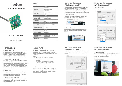
8MP Sony IMX219(SKU:B0196)QUICK START GUIDEUSB Camera ModuleSPECSHow to use the program (Windows demo only)The Menu bar at the top of the shown image con-tains few menu items and the current preview resolution and the frame rate are displayed on the bottom bar when the application is running. The following sections describe each of the menu items•Menu>DevicesThis menu will show the available video devices to host PC. The B0196 named USB Camera .•Menu>OptionsThe options menu can be used to select the pre-view and image parameters supported by this camera.How to use the program (Windows demo only)-Video Capture PinINTRODUCTION•About ArducamArducam has been a professional designer and manufacturer of SPI, MIPI, DVP and USB cameras since 2012. We also offer customized turnkey design and manufacturing solution services for customers who want their products to be unique.•About this USB CameraThe B0196 is a new member of the Arducam ’s USB camera family. It ’s an 8MP, UVC compliant, USB 2.0 camera. This USB camera is based on 1/4” Sony IMX219 image sensor, and you can learn more about its specs in the next chapter. Arducam also provides the sample application that demonstrates some features of this camera.•About UVCThe B0196 is a UVC -compliant camera. The native UVC drivers of Windows, Linux and Mac shall be compatible with this camera so that it does not require extra drivers to be installed.•About Customer ServiceIf you need our help or want to customize other models of USB cameras, feel free to contact us at *******************QUICK START•How to download the program1.Download the APP Amcap from the following link https:///downloads/app/AMCap.exe2.NOTE:If used with the Android device, USB Camera APP and connect adapter are needed.For Mac OS, please open the native software facetime and select the video camera “USB Camera” .•How to connect the cameraConnect the one end of the USB 2.0 cable to the USB 2.0 connector provided on the back of B0196, and connect the other end to the USB 2.0 host controller on the computer.How to use the program (Windows demo only)-Video Capture Filter -> Video Proc Amp/Camera ControlHow to use the program (Windows demo only)•Menu> CaptureThe capture menu is used to capture the still image and video by using this application. You can also select the related parameters.。
- 1、下载文档前请自行甄别文档内容的完整性,平台不提供额外的编辑、内容补充、找答案等附加服务。
- 2、"仅部分预览"的文档,不可在线预览部分如存在完整性等问题,可反馈申请退款(可完整预览的文档不适用该条件!)。
- 3、如文档侵犯您的权益,请联系客服反馈,我们会尽快为您处理(人工客服工作时间:9:00-18:30)。
USB 摄像头的工作原理目录1、简介2、分类3、工作原理4、结构和组件5、技术指标6、发展趋势一、简介1.0常规介绍2.0技术介绍一、简介1.0常规介绍摄像头(CAMERA)又称为电脑像机、电脑眼等,它作为一种视频入设备,在过去广泛地应用于视频会议、远程医疗、实时监控等方面。
近年以来,随着互联网技术的发展,网络速度的不断提高,再加上感光成像器件技术的日渐成熟并大量用于摄像头的产品制造上,使得它们的价格低到可以令普通老百姓可以接受消费水平。
同时这两年CAMERA被广泛应用于MOBILEPHONE,这样一来,更加促进了感光成像技术的进一步提高,如:30万像素,130万像素,200万像素,300万像素等。
一、简介2.0技术介绍ϒ 2.0 Technology of presentation技术介绍ϒGeneral Descriptionϒ简介The camera module is a sensors on board module designed for mobile applicationϒwhere low power consumption and small size are of utmost importance.Proprietary sensor technology utilizes advanced algorithms to cancelFixed PatternNoise (FPN),eliminate smearing, and drastically reduce blooming. All required camera functions are programmable through theSerial Camera Control Bus (SCCB )interface.The device can be programmed to provide image output in various fully processedϒand encoded formats.ApplicationϒPC Camera/ Dual Mode, and Cellular phonesϒVideo conference equipment, Machine vision, Security camera,ϒBiometrics, Digital Still Cameras二、分类1.0DIGITAL CAMERA数字式2.0DIGITAL STILL CAMERA模拟式二、分类1.0DIGITAL CAMERA数字式数字摄像头是直接将摄像单元和视频捕捉单元集成在一起,然后通过串、并口或USB接口连接到HOST SYSTEM上,现在CAMERA市场上的摄像头基本以数字式为主,而数字摄像头中又以新型数据传输接口的USB数字摄像头为主(独立),在手机和电脑上主要是直接通过IO(BTB/USB/MINI/ USB…)与HOST SYSTEM连接,经过SYSTEM的编辑后以数字信号输出到DISPLAY上显示。
目前CAMERA市场上主流的CAMERA都是DIGITAL CAMERA。
二、分类2.0SIMULANT CAMERA模拟式模拟摄像头是将视频采集设备产生的模拟视频信号转换成数字信号,进而将其存储到SYSTEM MEMORY里。
模拟摄像头捕捉到的视频信号必须经过特定的视频捕捉卡将模拟信号转换成数字模式,并加以压缩后才可以转换到HOST SYSTEM上运用,经过HOST SYSTEM 的编辑,通过DISPLAY显示和输出。
1.0GENERAL DESCRIP原理2.0SYSTEM SHOW摄像头主要由镜头、影像传感器(主要是CCD/CMOS器件)、DSP等组成,被摄物体经过镜头聚焦至CCD 上,CCD由多个X-Y纵横排列的像素点组成,每个像素都由一个光电二极管及相关电路组成,光电二极管将光线转变成电荷,收集到的电荷总量与光线强度成比例,所积累的电荷在相关电路的控制下,逐点移出,经滤波、放大,再经过DSP处理后形成视频信号输出。
1.0工作原理摄像头的工作原理大致为:景物通过镜头(LENS)生成的光学图像投射到图像传感器(SENSOR)表面上,然后转为电信号,经过A/D(模/数)转换后变成数字图像信号,再送到数字处理芯片(DSP)中加工处理,再通过I/O 接口传输到电脑中进行处理后,再通过显示屏(DISPLAY)就可以看到图像了。
工作原理方框图景物(SCE)图像传感器(SENSOR)数字信号处理芯片(DSP)电脑(PC)图像(PIC) LENSA/D(COMS无)I/O DISPLAY主控的内部工作原理四、组件与结构3017镜头(LENS)四、组件与结构1.0 LENS(镜头)ϒ一般CAMERA的镜头结构是有几片透镜组成,分有塑胶透镜(PLASTIC)和玻璃透镜(GLASS),ϒ通常CAMERA用的镜头结构有:1P,2P,1G1P,1G3P,2G2P,4G等。
透镜越多,成本越高;玻璃透镜比塑胶透镜贵,但是玻璃透镜的成像效果比塑胶透镜的成像效果要好。
目前市场上针对ϒMOBILE PHONE配置的CAMERA以1G3P(1片玻璃透镜和3片塑胶透镜组成)为主,目的是降低成本。
四、组件与结构CMOS传感器四、组件与结构7670传感器(SENSOR)四、组件与结构ϒ2.0 SENSOR(图象传感器)ϒ图像传感器(SENSOR)是一种半导体芯片,其表面包含有几十万到几百万的光电二极管。
光电二极管受到光照射时,就会产生电荷。
ϒ目前的SENSOR类型有两种:ϒCCD(Charge Couple Device),电荷耦合器件ϒCMOS(Complementary Metal Oxide Semiconductor),互补金属氧化物四、组件与结构CCD组件与结构结构ϒCCD结构一般分为三层:ϒ第一层“LENS”CAMERA的成像关键在于SENSOR,为了扩大CCD的采光率必须扩大单一象素的受光面积,在提高采光率的同时会导致画面质量下降。
ϒLENS就是相当于在SENSOR前面增加一副眼镜SENSOR的采光率就不是由SENSOR的开口面积决定而是由LENS的表面积决定。
ϒ第二层“分色滤色片”ϒ目前分色滤色片有两种分色方法:ϒ A. RGB原色分色法,就是三原色分色法,几乎所有的人类眼睛可以识别的颜色都可以通过R.G.B来组成,RGB就是通过这三个通道的颜色调节而成。
ϒ B. CMYK补色分色法,由四个通道的颜色配合而成,分别是青(C)、洋红(M)、黄(Y)、黑(K),但是调节出来的颜色不如RGB的颜色多。
ϒ第三层“感光层(SENSOR)”ϒCCD的第三层是处理芯片(SENSOR,SENSOR主要是将穿过滤色层的光源转换成电子信号,并将信号传送到影像DSP),将影像还原。
ϒ四、组件与结构CCD与CMOS的差异ϒ A. 总体比较ϒCCD的优点是灵敏度高,噪音小,信噪比大。
但是生产工艺复杂、成本高、功耗高。
ϒCMOS的优点是集成度高(将AADC与讯号处理器整合,可以大幅缩小体积)、功耗低、成本低。
但是噪音比较大、灵敏度较低、对光源要求高。
ϒ B. 成像效果ϒ在相同像素下CCD的成像往往通透性、明锐度都很好,色彩还原、曝光可以保证基本准确。
ϒCMOS的产品往往通透性一般,对实物的色彩还原能力偏弱,曝光也都不太好。
ϒ在采用CMOS为感光元器件的产品中,通过采用影像光源自动增益补强技术,自动亮度、白平衡控制技术,色饱和度、对比度、边缘增强以及伽马矫正等先进的影像控制技术,完全可以达到与CCD摄像头相媲美的效果。
ϒ C. 功耗比较ϒCCD功耗比较高,为使电荷传输顺畅,噪声降低,需要高压差改善传输效果;另外由于CCD无法ADC和讯号处理器,导致需要使用3~4组电源。
ϒCMOS功耗比较低,不到CCD的1/3,CMOS影像传感器将每一画素的电荷转换成电压,读取前就将其放大,利用3.3V的电源即可驱动,只需要一组电源。
以GC0307传感器为例介绍四、组件与结构2.外围电路说明ϒGC0307芯片只需要单电源供电,DVDD28 = 2.8V,其余电源VDD18,AVDD25 及数字参考电源VREF 管脚在模组内部通过电容接地。
不需要引出到模组连接器。
ϒ电源上加如图示C1、C2、C3,C4 滤波电容,容值均为0.1uF。
ϒ电容摆放时尽量靠近Pin 脚。
ϒRESET pin 没有引出,由芯片内部控制。
ϒSBCL/SBDA pin 内部已有上拉电阻,系统板可以不加上拉电阻。
四、组件与结构管脚说明:管脚号名称管脚类型功能/说明A1 AVDD25 电源模拟电路电压,内部产生,通过0.1µF或1uF 的电容接地A2 VREF 电源数字参考电源,通过0.1µF 的电容接地A3 SBDA 输入/出串行通讯口数据线A4 SBCL 输入串行通讯口时钟线A5 D7 输出YUV/RGB 输出位[7]B1 GND 电源模拟/数字地B2 PWDN 输入0:正常模式;1:省电模式B3 HSYNC 输出HREF 输出B4 D6 输出YUV/RGB 输出位[6]B5 D5 输出YUV/RGB 输出位[5]C1 VSYNC 输出VSYNC 输出C2 D0 输出YUV/RGB 输出位[0]C3 D3 输出YUV/RGB 输出位[3]C4 D4 输出YUV/RGB 输出位[4]C5 PCLK 输出Pixel 时钟输出D1 DVDD28 电源主供电电源2.8V,通过0.1µF 或1uF 的电容接地D2 D1 输出YUV/RGB 输出位[1]D3 D2 输出YUV/RGB 输出位[2]D4 DVDD18 电源数字电路电源,1.8V,内部产生,通过0.1µF或1uF 的电容接地D5 IN_CLK 输入系统时钟输入ϒ*D[7:0] 8 位YUV 或RGB 数据(D[7]MSB,D[0] LSB)ϒ**Reset 内部拉高,外部没有PIN 脚引出使用技巧使用摄像头,尤其是采用CMOS 芯片的产品时就更应该注重技巧:A.不要在逆光环境下使用(这点CCD 同),尤其不要直接指向太阳,否则“放大镜烧蚂蚁”的惨剧就会发生在您的摄像头上。
B.环境光线不要太弱,否则直接影响成像质量。
克服这种困难有两种办法,一是加强周围亮度,二是选择要求最小照明度小的产品,现在有些摄像头已经可以达到5lux 。
C.要注意的是合理使用镜头变焦,不要小瞧这点,通过正确的调整,摄像头也同样可以拥有拍摄芯片的功能。
受市场情况及市场发展等情况的限制,摄像头采用CCD 图像传感器的厂商为数不多,主要原因是采用CCD 图像传感器成本高的影响。