FEY FK6系列产品样本
奥豪斯系列电子天平使用手册

1.3 使用条件及注意事项...............................................................................................................- 3 -
1.4 天平使用的环境条件和使用前的准备...................................................................................- 3 -
4.9 锁定设置(Lockout).................................................................................................................- 35 -
5. 维护 .......................................................................................................................................................- 36 -
1.1
天平介绍 ...............................................................................................- 3 -
1.2 产品命名规则 ..........................................................................................................................- 3 -
SimpliFire SF-ALL48-BK 和 SF-ALL60-BK 产品说明书
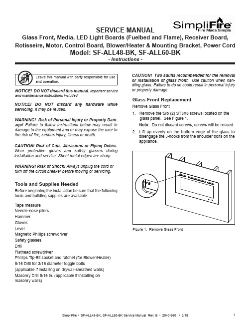
SERVICE MANUALGlass Front, Media, LED Light Boards (Fuelbed and Flame), Receiver Board, Rotisseire, Motor, Control Board, Blower/Heater & Mounting Bracket, Power CordCAUTION! Risk of Cuts, Abrasions or Flying Debris. Wear protective gloves and safety glasses duringinstallation and service. Sheet metal edges are sharp.NOTICE! DO NOT discard this manual. Important serviceand maintenance instructions included.NOTICE! DO NOT discard any hardware while servicing. It may be reused.WARNING! Risk of Shock! Always unplug the cord or turn off the circuit breaker before moving or servicing.Tools and Supplies NeededBefore beginning the installation be sure that the following tools and building supplies are available.Tape measure Needle-nose pliers Hammer Gloves LevelMagnetic Phillips screwdriver Safety glasses DrillFlathead screwdriverPhillips Tip-Bit socket and ratchet (for Blower/Heater)5/16 Drill for 3/16 diameter toggle bolts(applicable if installing on drywall-sheathed walls)Masonry Drill 5/16 in. (applicable if installing on masonry walls)Glass Front ReplacementRemove Glass Front1. Remove the two (2) ST3X8 screws located on theglass panel. See Figure 1. Note: Do not discard screws, screws will be reused. 2. Lift up evenly on the bottom edge of the glass to disengage the J-hooks from the shoulder bolts on the appliance.or property damage.Figure 1. Remove Glass FrontWARNING! Risk of Personal Injury or Property Dam-age! Failure to follow instructions below may result in damage to the equipment and or may expose the user to the risk of 昀椀re, serious injury, illness or death.Stone/Media Installation1. Remove Glass.2. Arrange the stone/media along the inset windowledge at the front of the appliance.Note: Extra media are provided and may bedistributed based on consumer preference. Not all media needs to be used.Glass Replacement (Continued)Installing Glass3. Install front panel. Locate the J-hooks on the back side of the glass on the four shoulder bolts on the appliance opening. Engage the shoulder bolts. See Figure 2.4. Press down on top edge of glass to fully engage J- hooks on the shoulder bolts.Note: Make sure the glass is fully attached to the 昀椀re-box so that the control panel can work properly.Figure 2. Glass Front Removal/Installation5. Thread the two (2) ST3X8 screws into the threaded holes on the glass panel. Check the alignment of the glass panel and securely tighten the screws. SeeFigure 3.Figure 3. Secure Glass Front1. Disconnect electrical service to the appliance. Forrecessed electrical installations that are hardwired,昀椀nd and shut-off service at the breaker. For wall-mounted installations that use a corded plug,disconnect the cord from the receptacle.2. Remove the glass front from the appliance. Use twopeople.3. Remove appliance the two screws in upper right andleft corners of the glass opening. Follow speci昀椀cinstructions from page 1 and 2 for removal of thefront glass. See Figure 4. CAUTION! Two adults recommended for the removal or installation of glass front. Use caution when han-dling glass. Failure to do so could result in personal injuryor property damage. Figure 4. Remove Upper Right & Left ScrewsPreparation for Component Installation4. Remove right and left side panels by turning thepanels inward. See Figure 5.Figure 5. Remove Right & Left Side Panels5. Using a 昀氀athead screwdriver, pry open the seventabs as shown in Figure 6. Pry the tabs upward at a30 degree angle. During this step, take care not toscratch or damage the glass panel behind the tabs.TABSFUELBED PLASTIC COVER Figure 6. Remove Plastic Cover6. Remove the fuelbed plastic cover that covers thefuelbed LED light strips. See Figure 6.LED Light Board InstallationThe LED Service Kit includes LED Light Boards for both the Fuelbed and the Flame effect.Determine which LED light set to be installed. See Figure 7.Figure 7. LED Light Board Identi昀椀cationLED FOR FUELBED1. Complete Steps 1-6 in Preparation for ComponentInstallation instructions. 2. Locate the Fuelbed LED Light Board cable. See Figure 8.LED LIGHT BOARD CABLE3. Unplug the LED Light Board cable. See Figure 9.LED LIGHT BOARD CABLEFigure 8. LED Light Board CableFigure 9. Unplug LED Light Board Cable4. Remove the LED light board from the bottom isolation columns. Starting at one end of the board use aLED FOR FLAMEFigure 10. Isolation Columns5. Remove and discard LED light board, replace with new LED light board. Install new LED light board by engaging the holes in the light board with the plastic barbs, and pressing into position. Reconnect the cables. See Figure 9.Fuelbed LED Light Board InstallationReceiver Board, Rotisseire, Motor, Flame LED Light Board, Control Board and Blower/ Heater Installation1. Complete Steps 1-6 in Preparation for ComponentInstallation instructions.3. Unplug Fuelbed LED Light Board, then lift it from theappliance set aside.Figure 12. Bracket Screw Location4. Remove seven (7) Phillips screws from the bracket. Remove the bracket. Set aside. See Figure 12.5. Carefully remove the glass panel. Rotate the top edge of the glass panel towards the opening, then lift out the the glass panel from the appliance. Set glass panel aside in a safe location, preferably a soft surface such as carpet or cardboard.Figure 11. Fuelbed LED Light Board Screw LocationReceiver Board Installation6. Locate the Receiver Board in the upper right side of appliance. See Figure 13.Figure 14. Receiver Board Cable7. Remove the Receiver Board from the isolationcolumns. Use a needle-nose pliers to compress the barbs on each isolation column.8. Unplug the cable, remove the Receiver Board and install with replacement board. See Figure 14.9. Reverse steps to complete installation.NOTE: The following steps (6-9) are only for re-placement of the Receiver Board.If replacing Rotisseire, Motor, Flame LED LightBoard, Control Board and/or Blower/Heater continue onto step 10.10. Remove two (2) Phillips screws at the bottom of the left and right side of the appliance opening. See11. Remove 14 Phillips screws at the top and bottom of the 昀氀ame screen. See Figure 16.12. Remove the 昀氀ame screen.Note: Be sure to place on a 昀氀at surface with the silk screen face-up. This is to prevent any distortion on the screen.13 Remove the center screw located in the the center of the Rotisseire. See Figure 17.14. Pull the Rotisseire to the left to disengage it from the motor, then remove the Rotisseire assembly.Figure 16. Flame Screen LocationFigure 17. Rotisseire Screw LocationIf replacing only the Rotisseire, install replacement part and reverse the installation steps.Be sure the 昀氀ame screen is installed correctly with the 昀氀ame silk screen to the outside and 昀氀ames at the bottom of the appliance.If replacing Motor continue to the next steps 15-18.Rotisseire InstallationIf replacing Flame LED Light Board continue to step 19.CAUTION! Risks of Cuts! Rotisseire has sharp edgesMotor InstallationThe motor is located in the lower right corner of the appliance.15. Remove the rubber shaft on the motor. See Figure 18.Figure 18. Rubber Shaft RemovalRUBBER SHAFT16. Remove the two screws on the motor. See Figure 19.Figure 19. Remove Motor Screws17. Unplug the motor cable connection. See Figure 20.Figure 20. Unplug Motor Cable18. Install replacement part and reverse the installation steps.Flame LED Light Board InstallationNOTE: The following steps (15-18) are only for re-placement of the motor.If replacing Flame LED Light Board, continue onto step 19.19. Remove screws used to attach the 昀氀ame screenFigure 21. Remove Flame Screen Bracket Screws.20. Remove 昀氀ame screen bracket.21. Unplug cable connection on each end of the LED Board. See Figure 22.Figure 22. Unplug LED Board Cable Connections22. Install replacement part and reverse the installation steps.Control Board Installation23. Remove the two (2) Phillips screws. After removing screws the mounting bracket can be lowered downto access the wires. See Figure 23.Figure 23. Remove Mounting Bracket Screws24. Unplug the 昀椀ve (5) pin and socket connectors between the Control Board and the wire harnesses. Tag and label the wire harnesses to ensure that wires will be reconnected correctly. See Figure 24.Figure 24. Unplug Control Board25. Install new Control Board and reverse the installation steps. Blower/Heater Installation26. Locate the four (4) screws on the mounting plate for the blower/heater module. See Figure 25.27. Remove the four (4) Phillips screws.Figure 25. Remove Mounting Plate Screws28. Drop the Blower/Heater module down on the shelf. See Figure 26.29. Reach up into the right end of the slot, and unplug the cable from the connector.Figure 26. Remove Blower/Heater30. Install new Blower/Heater and reverse the installationsteps.SHELFMasonry Wall •In the marked locations, drill 5/16 in. diameter x 2 in. deep holes. See Figure 30.• Insert the provided wall anchors into the holes. •Gently tap the anchors with a hammer until they are 昀氀ush with the wall surface.•With mounting hooks pointed up, attach the bracket to the masonry anchors with ST5X40 screws . SeeFigure 31.Figure 29. Installing Anchors in Hollow WallFigure 28. Toggle Bolt Installation through Mounting BracketFigure 30. Masonry Anchor PlacementFigure 27. 3/16 Toggle-Bolt Anchor•The toggle-bolt anchors are provided to accomodate the required anchor points based on the appliance. Use of toggle bolt anchors requires drywall thick-ness of minimum 1/2 in. and drilled holes size of 5/16 in. diameter.•Insert the bolt through the front side of the mounting bracket and thread the toggle onto it from the rear of the bracket. See Figure 28.•Fold the toggle wings 昀氀ush against the bolt and push them through a drilled hole until the toggle wings expand open on the other side. See Figure 29. •Pull back on the bolt and tighten. See Figure 29.Note: This product cannot be installed on a wall sheathed with drywall less than 1/2 in. thick, unless all six (6) anchor points in the mounting bracket align with structural framing members.WARNING! Risk of Damage or Personal Injury! Al-lowable pull-out and shear strength are 25% of ultimate values or less, as required by building authorities.Framed Wall •Locate the mounting bracket on the wall in thedesired location of the appliance. Level the bracket, then mark its location on the wall, including a mark-ing for each of the fastener holes in the bracket. •For each of the marked mounting point locations, determine which points align with a structural fram-ing member.•At the points where a wood or metal framing mem-ber exists, the ST5X40 screw can be installed directly into that structural member.•For every mounting hole that does not align with a structural framing member, a wall board toggle-bolt anchor must be used. See Figure 27.Direct Wall Mounting with Wall Mounting BracketThe wall mounting bracket can be installed on masonry walls such as those constructed of brick or concrete, or to framed walls constructed of wood or steel framing sheathed with gypsum wallboard, drywall, wood, etc. The method used to mount the mounting bracket is dif-ferent between masonry walls and framed walls. Refer to the following sections for more detail on the method applicable to this installation.11SimpliFire • SF-ALL48-BK, SF-ALL60-BK Service Manual Rev. B • 2040-960 • 3/18SimpliFire, a brand of Hearth & Home Technologies7571 215th Street West, Lakeville, MN 55044Please contact the SimpliFire customer/technical support hotline at 877-320-0730 with any questions or concerns.WARNING! Risk of Damage or Personal Injury! Do not use supplied masonry anchors on hollow walls,sheathed with wood, gypsum wallbaord, drywall or other materials.Figure 31. Bracket AttachmentWARNING! Risk of Fire, Electrical Shock and Injury! Ensure the power cord is not installed so that it is pinched or against a sharp edge and ensure that the power cord is stored or secure to avoid tripping and snagging.Power Cord Kit InstallationThe appliance power cord has a three pin NEMA-5-15P plug. The power cord should not be used unless a grounded receptacle is available.1. Remove the terminal block cover plate located on the right end of the appliance.2. Disconnect the terminal block from the three wires inside the appliance. Discard the terminal block cover plate.3. Connect the three appliance wires to the terminal block supplied with the power cord kit. See Figure 32.4. Replace cord kit terminal block cover plate and retaining screws. Plug cord into nearest outlet.Figure 32. Optional Power Cord Assembly InstallationLNR E DB L U EWire DiagramY E L L O W / G R E E N。
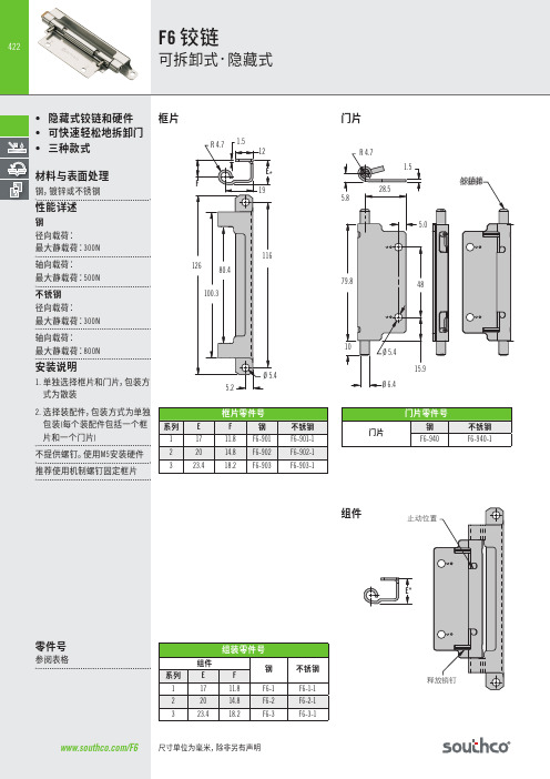
南科 F6 铰链说明书
附注
固定: *选择最适合于您的门布置E值 的框片。尺寸E+0.6=门框外表 面到门内表面的距离。
0.5間隙 D最大轉角,用於如圖的直角門
28.7±0.1 軸向
面板准备尺寸
系列
A
B
C
D
1
17.6
10.9
3.2
132º
2
20.6
12.7
3.9
125º
3
24
15.3
4.4
118º
徑向
門框 Ø 5.5±0.1 門框上固 定硬體位
M5 或 10-32 螺紋螺栓
2.4
15.5
2.4 18.5
18.5
零件号
款式
安装
材料
钢
不锈钢
成型
通孔
F6-905 F6-905-5
成型 M5螺纹螺栓 F6-908 F6-908-5
Байду номын сангаас
成型 10-32螺纹螺栓 F6-907
F6-907-5
扁平型
焊接
F6-904 F6-904-5
18.4 18.4
2.4 2.4
Ø 6.7
Ø 6.7 38
38
/F6 尺寸单位为毫米,除非另有声明
成型框片
徑向 A型門片
425
軸向 A型門片
安装说明
需��订购1个门片和1个框片 组成整套装配
不随附螺钉。 铰链安装方式有以下两种: M5(10号)安装硬件(建议使用机 械螺钉)或焊接
A型門片
銷釘允許 行程50毫米
E* 釋放銷釘
423
门几何外形的任 何部分的外接圆 半径 B最大,以 保证铰链 和硬体的安装 和使用
美国Eaton公司产品说明书:Eaton Moeller系列xPole - mRB4 6 RCBO

Eaton 120654Eaton Moeller series xPole - mRB4/6 RCBO - residual-current circuit breaker with overcurrent protection. RCD/MCB, 16A, 100mA, B-LS-Char, 3N pole, FI-Char: AGeneral specificationsEaton Moeller series xPole - mRB4/6 RCBO - residual-current circuit breaker with overcurrent protection120654401508118484280 mm 75.5 mm 70 mm 0.446 kg CE Marked RoHS conformCE mRB6-16/3N/B/01-AProduct NameCatalog Number EANProduct Length/Depth Product Height Product Width Product Weight Compliances Certifications Model CodeSwitchgear for residential and commercial applicationsmRB6Combined RCD/MCB devicesSwitchgear for industrial and advanced commercial applications Three-pole + N44BB16 A6 - 25 Ampere0.1 AType A, pulse-current sensitiveRCBO AC400 V230 V / 400 V400 V500 V4 kV30, 100, 300 MilliAmpere Partly surge-proof, 250 A 50 HzA6 kA6 kA6 kA0.5 x I∆n6 kA6 kA6 kAApplicationProduct rangeBasic functionProduct applicationNumber of polesNumber of poles (protected) Number of poles (total) Tripping characteristic Release characteristicRated currentRated current of product range Fault current rating Sensitivity typeType Voltage typeVoltage ratingVoltage rating at ACRated operational voltage (Ue) - maxRated insulation voltage (Ui)Rated impulse withstand voltage (Uimp)Rated fault currents of product rangeImpulse withstand currentFrequency ratingLeakage current typeRated switching capacityRated switching capacity (IEC/EN 60947-2)Rated switching capacity (IEC/EN 61009)Rated non-tripping currentRated short-circuit breaking capacity (EN 60947-2) Rated short-circuit breaking capacity (EN 61009) Rated short-circuit breaking capacity (EN 61009-1) Rated short-circuit breaking capacity (IEC 60947-2)0 kA 0.25 kAUndelayed Non-delayed 100 Ampere gL 3III245 mm480 mm70 mmTri-stable slide catch - enables removal from existing busbar combinationIP20IP40Twin-purpose1 - 25 Square MillimeterBusbar tag shroud to VBG41 mm²25 mm²1 mm²25 mm²2 mmIEC 68-2: 25 °C - 55 °C at 90 % - 95 % humiditySurge current capacityDisconnection characteristic TrippingBack-up fuseSelectivity class Overvoltage category Pollution degree FrameWidth in number of modular spacingsDevice heightBuilt-in depthMounting styleDegree of protectionDegree of protection (built in)Terminals (top and bottom)Solid terminal capacitiesTerminal protectionConnectable conductor cross section (solid-core) - min Connectable conductor cross section (solid-core) - max Connectable conductor cross section (multi-wired) - min Connectable conductor cross section (multi-wired) - max Material thicknessClimatic proofing16 A0 W 11.6 W 0 W0 W-25 °C 40 °C Meets the product standard's requirements.Meets the product standard's requirements.Meets the product standard's requirements.Meets the product standard's requirements.Meets the product standard's requirements.Does not apply, since the entire switchgear needs to be evaluated.Does not apply, since the entire switchgear needs to be evaluated.Meets the product standard's requirements.Does not apply, since the entire switchgear needs to be evaluated.Meets the product standard's requirements.Does not apply, since the entire switchgear needs to be evaluated.Does not apply, since the entire switchgear needs to be evaluated.Is the panel builder's responsibility.Is the panel builder's responsibility.Is the panel builder's responsibility.Rated operational current for specified heat dissipation (In) Heat dissipation per pole, current-dependentEquipment heat dissipation, current-dependentStatic heat dissipation, non-current-dependentHeat dissipation capacityAmbient operating temperature - minAmbient operating temperature - max 10.2.2 Corrosion resistance10.2.3.1 Verification of thermal stability of enclosures10.2.3.2 Verification of resistance of insulating materials to normal heat10.2.3.3 Resist. of insul. mat. to abnormal heat/fire by internal elect. effects10.2.4 Resistance to ultra-violet (UV) radiation10.2.5 Lifting10.2.6 Mechanical impact10.2.7 Inscriptions10.3 Degree of protection of assemblies10.4 Clearances and creepage distances10.5 Protection against electric shock10.6 Incorporation of switching devices and components10.7 Internal electrical circuits and connections10.8 Connections for external conductors10.9.2 Power-frequency electric strengthIs the panel builder's responsibility.Is the panel builder's responsibility.The panel builder is responsible for the temperature rise calculation. Eaton will provide heat dissipation data for the devices.Is the panel builder's responsibility. The specifications for the switchgear must be observed.Is the panel builder's responsibility. The specifications for the switchgear must be observed.The device meets the requirements, provided the information in the instruction leaflet (IL) is observed.3Concurrently switching N-neutralIEC/EN 61009eaton-xpole-mrb4-rcbo-catalog-ca019058en-en-us.pdfeaton-xpole-mrb6-rcbo-catalog-ca019057en-en-us.pdfDA-DC-03_mRB-3N03_mRB-3p_20041603_mRB-3N_281118eaton-mcb-xpole-mrb4-6-characteristic-curve.epseaton-xeffect-frbm6/m-characteristic-curve-002.jpgDimensions xPole mRB4/mRB6 3Neaton-xeffect-frbm6/m-dimensions-004.jpgeaton-mcb-xpole-mrb4-6-dimensions.eps3D Drawing xPole mRB4/mRB6 3Neaton-xpole-combined-mcb-rcd-device-rcbo-packaging-manual-multilingual.pdfIL019140ZUDA-CS-faz_3pn_4pDA-CD-faz_3pn_4pCharacteristics xPole mRB4/mRB6 3Neaton-mcb-xpole-mrb4-6-wiring-diagram.epsContact Sequence xPole mRB4/mRB6 3N10.9.3 Impulse withstand voltage10.9.4 Testing of enclosures made of insulating material 10.10 Temperature rise10.11 Short-circuit rating10.12 Electromagnetic compatibility10.13 Mechanical function Current limiting class FeaturesStandards Catalogues Certification reports Characteristic curve DrawingsInstallation instructions mCAD modelTime/current curves Wiring diagramsEaton Corporation plc Eaton House30 Pembroke Road Dublin 4, Ireland © 2023 Eaton. All rights reserved. Eaton is a registered trademark.All other trademarks areproperty of their respectiveowners./socialmediaeaton-xeffect-frbm6/m-wiring-diagram-002.jpg。
FK6-1000型加弹机培训教材

FK6-1000型加弹机培训教材XX有限公司员工培训教材(试行)第一节:FK6-1000型加弹机的构造及功能简介第二节:加弹生产知识介绍第三节:加弹机维修保养知识介绍第四节:加弹生产工艺举例说明第五节:结束语:我所面临的使命第一节:FK6-1000型加弹机的构造及功能简介1、喂丝罗拉喂丝罗拉的作用是实现丝条的传输作用。
喂丝装置有两种组成方法。
即1):喂丝罗拉与皮辊型;2)喂丝罗拉与皮圈型。
其中喂丝罗拉为主动轴,表面镀铬抛光;皮圈(或皮辊)靠弹簧的加压压在喂丝罗拉上,为从动型。
2、喂丝罗拉前的横动移丝器它的作用是避免丝条对罗拉的集中磨损,延长皮圈(或压辊)的使用寿命。
生产加弹丝时,移丝间距一般为5-10mm。
移丝位置不正时,不能保证丝条在喂丝皮圈(或压辊)的规定范围内运行,从而不能保证丝条按规定的工艺要求执行。
如一、二罗拉前横动移丝器位置不正,就不能保证丝条正常牵伸的实现,引起缠丝。
3、第一加热器第一加热器又叫变型热箱,是接触式加热方式,1000M型长为2.5m,V型长为2.0m.。
其作用是加热丝条呈塑化状态,降低拉伸变形应力。
第一热箱温度提高,纤维的卷曲性和膨松性提高,染色变浅。
在实际生产中,我们必须经常地检查热箱的丝道,并每隔2-3个月要进行一次清洁。
因为一热箱温度的高低直接影响丝的卷曲性、膨松性。
进而影响染色性能。
故生产中丝越偏离热箱丝道,则变形丝条越差,染色等级越低。
如果大部分或完全跑出丝道,则成品丝将成僵丝。
4、冷却板冷却板的作用是对纤维在加捻以后卷曲结构的固定,如果冷却不佳(或不均匀),则纤维在加捻过程形成的卷曲结构就不均匀,进而影响染色均匀性,导致染色降等。
加弹机的丝条冷却用冷却板冷却。
5、假捻器假捻器的作用是产生机械扭曲应力,以便变形加工。
它是加弹机的核心。
6、第二罗拉(中间罗拉)中间罗拉很重要,通常它的速度即所谓的车速。
要求它的皮圈架握持力要强,防止逃捻丝的发生。
7、第二加热器第二加热器又叫定型热箱,是非接触式。
DW01AK6中文规格书
• 保护条件
正常状态下,如果电池放电使VDD端电压降低至过 电压放电保护阈值VOD,且持续时间超过过电压放电保 护延迟时间tOD,则 DW01AK6将使放电控制端DOUT由高电 平 转 为 VSS 端 电 平 ( 低 电 平 ), 从 而 使 外 接 放 电 控 制 N-MOS管Q2 关闭,放电回路被“切断”,即DW01AK6进
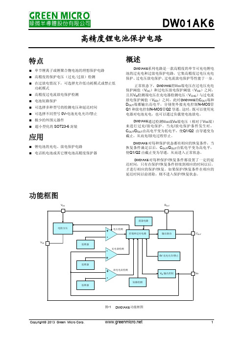
DW01AK6
高精度锂电池保护电路
特点
单节锂离子或锂聚合物电池的理想保护电路 高精度的保护电压(过充/过放)检测 在过放电情况下,可选择允许低功耗模式或禁止低 功耗模式 高精度过电流放电保护检测 电池短路保护 可选择多种型号的检测电压和延迟时间 可选择不同型号 0V-电池充电允许/禁止 极少的外围元器件 超小型化的 SOT23-6 封装
VDD=2.0V
V0V_CHG 充电器电压
电池电压, V0V_INH VM=-2.0V
最小值
典型值
最大值
单位
♦
1.5
10
V
VOCTYP-0.050
VOCTYP
VOCTYP+0.050
V
♦
VOCTYP-0.080
VOCTYP
VOCTYP+0.080
V
VOCRTYP-0.050 VOCRTYP VOCRTYP+0.050
DW01AK6 对每种保护/恢复条件都设置了一定的延 迟时间,只有在保护/恢复条件持续到相应的时间以后, 才进行相应的保护/恢复。如果保护/恢复条件在相应的 延迟时间以前消除,则不进入保护/恢复状态。
功能框图
VDD
电阻分压
VSS
基准源
基准源
基准源
莫贾V2416A系列迷你型无风扇、振动防护计算机产品介绍说明书

V2416A SeriesCompact,fanless,vibration-proof computers for rolling stock applicationsFeatures and Benefits•Intel Celeron/Core i7processor•Two hot-swappable2.5-inch HDD or SSD storage expansion trays•Dual independent DVI-I displays•2Gigabit Ethernet ports with M12X-coded connectors•2CFast sockets for OS backup•M12A-coded power connector•Compliant with EN50121-4•Complies with all EN50155mandatory test items1•IEC61373certified for shock and vibration resistance•Ready-to-run Debian7,Windows Embedded Standard7,and Windows10Embedded IoT Enterprise2016LTSB platforms•-40to70°C wide-temperature models available•Supports SNMP-based system configuration,control,and monitoring(Windows only)CertificationsIntroductionThe V2416A Series embedded computers are based on the Intel3rd Gen processor and feature4RS-232/422/485serial ports,dual LAN ports,and 3USB2.0hosts.In addition,the V2416A computers provide dual DVI-I outputs and comply with the mandatory test items of the EN50155 standard,making them suitable for a variety of industrial applications.The CFast socket,SATA connectors,and USB sockets provide the V2416A computers with the reliability needed for industrial applications that require data buffering and storage expansion.Most importantly,the V2416A computers come with2hot-swappable storage trays for inserting additional storage media,such as hard disk or solid-state drives,and support hot swapping for convenient,fast,and easy storage replacement. Each storage tray has its own LED to indicate whether or not a storage module is plugged in.The V2416A Series computers come preinstalled with a choice of Linux Debian7or Windows Embedded Standard7to provide programmers with a familiar environment in which to develop sophisticated,bug-free application software at a low cost.1.This product is suitable for rolling stock railway applications,as defined by the EN50155standard.For a more detailed statement,click here:/doc/specs/EN_50155_Compliance.pdfAppearanceFront View Rear ViewSpecificationsComputerCPU V2416A-C2Series:Intel®Celeron®Processor1047UE(2M cache,1.40GHz)V2416A-C7Series:Intel®Core™i7-3517UE Processor(4M cache,up to2.80GHz) System Chipset Mobile Intel®HM65Express ChipsetGraphics Controller Intel®HD Graphics4000(integrated)System Memory Pre-installed4GB DDR3System Memory Slot SODIMM DDR3/DDR3L slot x1Supported OS Linux Debian7Windows Embedded Standard7(WS7E)32-bitWindows Embedded Standard7(WS7E)64-bitStorage Slot CFast slot x2Computer InterfaceEthernet Ports Auto-sensing10/100/1000Mbps ports(M12X-coded)x2Serial Ports RS-232/422/485ports x4,software selectable(DB9male)USB2.0USB2.0hosts x1,M12D-coded connectorUSB2.0hosts x2,type-A connectorsAudio Input/Output Line in x1,Line out x1,M12D-codedDigital Input DIs x6Digital Output DOs x2Video Input DVI-I x2,29-pin DVI-D connectors(female)Digital InputsIsolation3k VDCConnector Screw-fastened Euroblock terminalDry Contact On:short to GNDOff:openI/O Mode DISensor Type Dry contactWet Contact(NPN or PNP)Wet Contact(DI to COM)On:10to30VDCOff:0to3VDCDigital OutputsConnector Screw-fastened Euroblock terminalCurrent Rating200mA per channelI/O Type SinkVoltage24to40VDCLED IndicatorsSystem Power x1Storage x1Hot-swappable2LAN2per port(10/100/1000Mbps)Serial2per port(Tx,Rx)Serial InterfaceBaudrate50bps to921.6kbpsFlow Control RTS/CTS,XON/XOFF,ADDC®(automatic data direction control)for RS-485,RTSToggle(RS-232only)Isolation N/AParity None,Even,Odd,Space,MarkData Bits5,6,7,8Stop Bits1,1.5,2Serial SignalsRS-232TxD,RxD,RTS,CTS,DTR,DSR,DCD,GNDRS-422Tx+,Tx-,Rx+,Rx-,GNDRS-485-2w Data+,Data-,GNDRS-485-4w Tx+,Tx-,Rx+,Rx-,GNDPower ParametersInput Voltage12to48VDCPower Connector M12A-coded male connectorPower Consumption(Max.) 3.3A@12VDC0.82A@48VDCPower Consumption40W(max.)Physical CharacteristicsHousing AluminumIP Rating IP30Dimensions(with ears)250x86x154mm(9.84x3.38x6.06in)Dimensions(without ears)275x92x154mm(10.83x3.62x6.06in)Weight4,000g(8.98lb)Installation DIN-rail mounting(optional),Wall mounting(standard) Protection-CT models:PCB conformal coating Environmental LimitsOperating Temperature Standard Models:-25to55°C(-13to131°F)Wide Temp.Models:-40to70°C(-40to158°F) Storage Temperature(package included)-40to85°C(-40to185°F)Ambient Relative Humidity5to95%(non-condensing)Standards and CertificationsEMC EN55032/24EMI CISPR32,FCC Part15B Class AEMS IEC61000-4-2ESD:Contact:6kV;Air:8kVIEC61000-4-3RS:80MHz to1GHz:20V/mIEC61000-4-4EFT:Power:2kV;Signal:2kVIEC61000-4-5Surge:Power:2kVIEC61000-4-6CS:10VIEC61000-4-8PFMFRailway EN50121-4,IEC60571Railway Fire Protection EN45545-2Safety EN60950-1,IEC60950-1Shock IEC60068-2-27,IEC61373,EN50155Vibration IEC60068-2-64,IEC61373,EN50155DeclarationGreen Product RoHS,CRoHS,WEEEMTBFTime332,173hrsStandards Telcordia(Bellcore),GBWarrantyWarranty Period3yearsDetails See /warrantyPackage ContentsDevice1x V2416A Series computerInstallation Kit8x screw,for storage installation2x storage key1x wall-mounting kit8x washer,for HDD/SSDDocumentation1x document and software CD1x quick installation guide1x warranty cardDimensionsOrdering InformationModel Name CPU Memory(Default)OS CFast(CTO)Backup CFast(CTO)Hot-SwappableSSD/HDD Tray(CTO)Operating Temp.ConformalCoatingV2416A-C2Celeron1047UE4GB or optional1(Optional)1(Optional)2(Optional)-25to55°C–V2416A-C2-T Celeron1047UE4GB or optional1(Optional)1(Optional)2(Optional)-40to70°C–V2416A-C2-CT-T Celeron1047UE4GB or optional1(Optional)1(Optional)2(Optional)-40to70°C✓V2416A-C7i7-3517UE4GB or optional1(Optional)1(Optional)2(Optional)-25to55°C–V2416A-C7-T i7-3517UE4GB or optional1(Optional)1(Optional)2(Optional)-40to70°C–V2416A-C7-CT-T i7-3517UE4GB or optional1(Optional)1(Optional)2(Optional)-40to70°C✓V2416A-C2-W7E Celeron1047UE4GB8GB1(Optional)2(Optional)-25to55°C–V2416A-C2-T-W7E Celeron1047UE4GB8GB1(Optional)2(Optional)-40to70°C–V2416A-C7-T-W7E Core i7-3517UE4GB8GB1(Optional)2(Optional)-40to70°C–Accessories(sold separately)Battery KitsRTC Battery Kit Lithium battery with built-in connectorCablesCBL-M12XMM8PRJ45-BK-100-IP67M12-to-RJ45Cat-5E UTP gigabit Ethernet cable,8-pin X-coded male connector,IP67,1mCBL-M12(FF5P)/Open-100IP67A-coded M12-to-5-pin power cable,IP67-rated5-pin female M12connector,1mConnectorsM12A-5PMM-IP685-pin male circular threaded D-coded M12USB connector,IP68M12X-8PMM-IP678-pin male X-coded circular threaded gigabit Ethernet connector,IP67M12A-5P-IP68A-coded screw-in sensor connector,female,IP68,4.05cmM12A-8PMM-IP678-pin male circular threaded A-codes M12connector,IP67-rated(for field-installation)Power AdaptersPWR-24270-DT-S1Power adapter,input voltage90to264VAC,output voltage24V with2.5A DC loadPower CordsPWC-C7AU-2B-183Power cord with Australian(AU)plug,2.5A/250V,1.83mPWC-C7CN-2B-183Power cord with two-prong China(CN)plug,1.83mPWC-C7EU-2B-183Power cord with Continental Europe(EU)plug,2.5A/250V,1.83mPWC-C7UK-2B-183Power cord with United Kingdom(UK)plug,2.5A/250V,1.83mPWC-C7US-2B-183Power cord with United States(US)plug,10A/125V,1.83mAntennasANT-WDB-ANF-0407 2.4/5GHz,omni-directional antenna,4/7dBi,N-type(male)Wall-Mounting KitsV2400Isolated Wall Mount Kit Wall-mounting kit with isolation protection,2wall-mounting brackets,4screwsDIN-Rail Mounting KitsDK-DC50131DIN-rail mounting kit,6screws©Moxa Inc.All rights reserved.Updated Jun12,2019.This document and any portion thereof may not be reproduced or used in any manner whatsoever without the express written permission of Moxa Inc.Product specifications subject to change without notice.Visit our website for the most up-to-date product information.。
MX+OFWY6 无源型分励+辅助 使用说明书

MX+OFWY6 无源型分励+辅助使用说明书安装、使用产品前,请仔细阅读使用说明书,并妥善保管备用。
安全告知在安装、操作、运行、维护、检查之前,请务必认真阅读本说明书,并按照说明书上的内容准确安装、使用本产品。
危险:●严禁湿手操作辅助触头和分励触头;●使用中,严禁触摸导电部位;●维护与保养时,必须确保产品不带电;●严禁用短路的办法来测试产品;注意:●安装、维护与保养时,应由具有专业资格的人员操作;●产品的各项特性出厂时已整定,使用中不能自行拆装或随意调节;●使用前请确认产品工作电压、额定电流、频率及特性是否符合工作要求;●为防止相间短路,应对接线端裸露导线或铜母线进行绝缘处理;●如果产品在开箱时有破损或异常响声,应立即停止使用并联系供应商;●产品报废时,请做好产业废弃物处理,谢谢您的合作;目录1主要用途及适用范围 (1)2产品介绍 (1)2.1面板介绍 (1)2.2产品型号介绍 (2)3正常使用、安装及运输条件 (2)3.1使用、安装条件 (2)3.2贮存、运输条件 (2)4技术特性 (2)4.1主要技术参数 (2)5外形及安装尺寸 (3)5.1外形及安装尺寸见下图 (3)5.2接线图示意 (3)6安装和使用维护 (4)6.1安装 (4)6.2维护与保养 (4)7开箱检查 (5)8公司承诺 (5)1主要用途及适用范围MX+OFWY6主要与CDB6系列断路器进行拼装,实现远距离操作控制。
2产品介绍2.1面板介绍说明:1公司商标6扭矩、剥线指示2产品名称7敲落孔盖3额定电压8技术参数4接线端子指示9二维码5拼装示意图2.2产品型号介绍设计序号无源型分励+辅助代号3正常使用、安装及运输条件3.1使用、安装条件a)周围空气温度上限不超过+70℃, 下限不低于-35℃,并且在24小时内平均温度不超过+35℃;b)安装地点的海拔不超过2000m;c)温度为+40℃时,空气的相对湿度不超过50%;在较低温度下允许有较大的相对湿度,例如在+20℃时,相对湿度不超过90%,对于温度变化偶尔产生凝露应采取特殊的保护措施;d)安装在无爆炸危险的介质中,且介质中无足以腐蚀金属和破坏绝缘的气体与尘埃;e)安装在无显著冲击振动及无雨雪侵袭的地方;f)污染等级:2级;g)安装类别:Ⅱ类、Ⅲ类;h)防护等级:IP20;3.2贮存、运输条件a)温度下限不低于-40℃,上限不超过+70℃;b)相对湿度(25℃)不超过95%;c)产品在运输过程中应轻搬轻放,不应倒放,应尽量避免剧烈碰撞;4技术特性4.1主要技术参数基本参数额定绝缘电压(Ui):500V;额定冲击耐受电压:2.5KV;额定频率:50/60Hz;主要性能指标(1)触头使用类别:AC12、DC12;(2)分励控制电压:AC:100-415V/DC:110-130V;AC/DC:24V/48V;AC/DC:12V/24V;5外形及安装尺寸5.1外形及安装尺寸下图外形及安装尺寸5.2 接线示意图6安装和使用维护6.1安装a)安装前先检查产品标志与所使用的的条件是否相符;b)无源型分励+辅助脱扣器拼装在断路器左侧:附件拼装总宽54mm内,从左至右的顺序及数量:OF6/FF6/FS6/SD6(3 max.)+MO6/MV6/MN6/MVMN6/MSN6/MOWY6(2 max.)+MCB;c)无源型分励+辅助脱扣器左侧拼装产品时,需在拼装前去除敲落孔盖(面板介绍图7处);d)将脱扣器合、分几次检查操作机构有无卡滞现象,机构动作是否可靠;e)安装方式:采用TH35-7.5型安装轨;f)与CDB6i、CDB6LEi、CDB6Pi、CDB6PLEi、CDBK、CDBLEK、CDBKPLE等型号小型断路器配装使用,实现远距离操作控制;6.2维护与保养a)维护与保养时,必须由具有专业资格的人员操作;b)必须确保产品不带电;c)在正常操作条件下每年维护与保养一次,维护内容见表5:表5 维护与保养7开箱检查用户开箱后必须检查产品是否完好无损,外露金属是否生锈,是否因运输和保管不善造成产品有所缺陷,如有上述现象,产品则不能使用,请及时与供应商联系解决。
- 1、下载文档前请自行甄别文档内容的完整性,平台不提供额外的编辑、内容补充、找答案等附加服务。
- 2、"仅部分预览"的文档,不可在线预览部分如存在完整性等问题,可反馈申请退款(可完整预览的文档不适用该条件!)。
- 3、如文档侵犯您的权益,请联系客服反馈,我们会尽快为您处理(人工客服工作时间:9:00-18:30)。
CATALOG A9Fey Lamellenringe GmbH & Co. KGS E A L I N G R I N G SR E T A I N I N G R I N G SFey Lamellenringe Vertriebs GmbH, Austria©Copyrightby FeyLamellenringe They are used as They are also used as a protection seal in front of hermetically acting seal 6" laminar rings must meet special sealing requirements against grease leakage and against "FK 6" laminar rings provide a uniform radial tension and, in contrast to the "FK 3"The combined ring sets "FK6 ASKD" (additional sealing of the groove base unlimitedRing carrier/shaftAttention: The groove width must bewidened by at least 10% andGLEITMO 980 must be usedfor speeds above 1,000 RPM.Axial playRadialplaAxial and/or radial play 3):The groove width "A" must be widened by twice the play if play occurs in the area of the rings.The groove base diameter "must be reduced by the radial play if radial play occurs.Damage to the rings and the surrounding components occur if this is not adhered to.It is recommended to use the full groove width tolerances, especially in the case of thermall expansion.Installation information:See pages 38 and 39.Order information 4):The ring diameter information must match the housing or shaft diameter dimensions "D" for all inquiries and/or orders.The rings can be ordered individually or in sets (1 set = 2 ASD rings).Run and installation tests:Run and installation tests under operating conditions must be performed in each case before standard production of our laminar rings can begin to determine whether the desired sealing effects can be achieved.- 2.6- 3.0- 3.6- 4.2- 5.0- 5.4- 5.8- 6.2- 6.8- 7.2- 7.6- 8.2 2.92.92.92.93.23.23.23.63.63.63.63.61.31.31.31.31.451.451.451.651.651.651.651.651.01.21.51.82.22.42.62.83.13.33.53.8Tolerance Nominal dimension Ring dimensions Groove dimensionsTolerance Tolerance Tolerance Tolerance RB RD A D 2=D 1minus +0.08- 0.04+0.1-0.1H 6H 7+0.1-0+0-0.2in accordance withmanufacturer'sselectionin accordance with manu-facturer's selectionSee p a ge38©Copyrightby FeyLamellenringe Double wound laminar sealing rings "FK6 ASKD" are used as a grease seal for roller and plain bearings and they protect,if greased, against grease leakage as well as against dust, dirt and splash water ingress, especially if the sealing requi-Due to the increased labyrinth effect, the sealing effect is optimized by the additional sealing of the groo-max.10 m/sRing carrier/shaftAttention: The groove width must bewidened by at least 10% andGLEITMO 980 must be usedfor speeds above 1,000 RPM.Axial playRadi alpla Axial and/or radial play 3):The groove width "A" must be widened by twice the play if play occurs in the area of the rings.meter "D 2" must be reduced by the radial play if radial play occurs.nents occurs if this is not adhered to.of thermal expansion.Installation information:See pages 38 and 39.Order information 4):The ring diameter information must match the housing or shaft diameter dimensions "DThe rings can be ordered individually or in sets (1 set = 2 ASD rings + 1 ISD rings).Run and installation tests:Run and installation tests under operating conditions must be performed in each case before standard production of our 1 ISD-ring{- 2.6- 3.0- 3.6- 4.2- 5.0- 5.4- 5.8- 6.2- 6.8- 7.2- 7.6- 8.2 4.34.34.34.34.84.84.85.45.45.45.45.41.31.31.31.31.451.451.451.651.651.651.651.6524.929.935.9- 42.948.9- 51.9- 59.9- 69.974.979.989.999.9 1.01.21.51.82.22.42.62.83.13.33.53.8Tolerance Nominal dimension Ring dimensions Groove dimensionsTolerance Tolerance Tolerance Tolerance RB RD A R1D 2=D 1minus min.1+0.1-0+0-0.2+0.08- 0.04+0.1-0.1H 6H 7in accordance with manufacturer's selection in accordance with manu-facturer's selection in accordance withmanufacturer'sselectionin accordance with manu-facturer's selectionSeep a ge38©Copyrightby FeyLamellenringe Double wound laminar sealing rings "FK6 ISD" are used as a grease seal for roller and plain bearings and they protect,if greased, against grease leakage as well as against dust, dirt and splash water ingress, especially if the sealing require-Double wound laminar rings provide a uniform radial tension and, in contrast to the single wound "FK3"The combined ring sets "FK6 ISKD" (additional sealing of the groove base max.10 m/sRing carrier/shaftAttention: The groove width must bewidened by at least 10% andGLEITMO 980 must be usedfor speeds above 1,000 RPM.Axial playRadi alpl a Axial and/or radial play 3):The groove width "A" must be widened by twice the play if play occurs in the area of the rings.The groove base dia- meter "D2" must be increased by the radial play if radial play occurs.Damage to the rings and the surrounding compo-nents occurs if this is not adhered to.It is recommended to use the full groove width tolerances, especially in the caseof thermal expansion.Installation information:See pages 38 and 39.Order information 4):The ring diameter information must match shaft diameter dimensions "D1" for all inquiries and/or orders.The rings can be ordered individually or in sets (1 set = 2 ISD rings).Run and installation tests:Run and installation tests under operating conditions must be performed in each case before standard production of our laminar rings can begin to determine whether the desired sealing effects can be achieved.+ 2.6+ 3.0+ 3.6+ 4.2+ 5.0+ 5.4+ 5.8+ 6.2+ 6.8+ 7.2+ 7.6+ 8.2 2.92.92.92.93.23.23.23.63.63.63.63.61.31.31.31.31.451.451.451.651.651.651.651.651.01.21.51.82.22.42.62.83.13.33.53.8Tolerance Nominal dimension Ring dimensions Groove dimensionsTolerance Tolerance Tolerance Tolerance RB RD A D 2=D 1plus +0.1-0+0.2-0+0.08- 0.04+0.1-0.1h 6h 7in accordance withmanufacturer'sselectionin accordance with manu-facturer's selectionSeep a ge38©Copyrightby FeyLamellenringe Double wound laminar sealing rings "FK6 ISKD" are used as a grease seal for roller and plain bearings and they protect,if greased, against grease leakage as well as against dust, dirt and splash water ingress, especially if the sealing re-Due to the increased labyrinth effect, the sealing effect is optimized by the additional sealing of the max.10 m/sRing carrier/shaftAttention: The groove width must bewidened by at least 10% andGLEITMO 980 must be usedfor speeds above 1,000 RPM.Axial playRadi alpla Axial and/or radial play 3):The groove width "A" must be widened by twice the play if play occurs in the area of the rings.meter "D2" must be increased by the radial play if radial play occurs.nents occurs if this is not adhered to.of thermal expansion.Installation information:See pages 38 and 39.Order information 4):The ring diameter information must match shaft diameter dimensions "Dbe ordered individually or in sets (1 set = 2 ISD rings + 1 ASD ring).Run and installation tests:Run and installation tests under operating conditions must be performed in each case before standard production of our 1 ASD-ring{+ 2.6+ 3.0+ 3.6+ 4.2+ 5.0+ 5.4+ 5.8+ 6.2+ 6.8+ 7.2+ 7.6+ 8.2 4.34.34.34.34.84.84.85.45.45.45.45.41.31.31.31.31.451.451.451.651.651.651.651.6515 - 24.925 - 29.930 - 35.9- 42.948.9- 51.9- 59.9- 69.974.979.989.999.9 1.01.21.51.82.22.42.62.83.13.33.53.8Shaft Tolerance Nominal dimension Ring dimensions Groove dimensions Tolerance Tolerance Tolerance Tolerance RB RD A D 2=D 1plus +0.1-0+0.2-0+0.08- 0.04+0.1-0.1h 6h 7in accordance with manufacturer's selection in accordance with manu-facturer's selection in accordance withmanufacturer'sselectionin accordance with manu-facturer's selectionS ee p a ge38。