IVA-CPT 测试评估系统使用手册
维特斯 VSC8584 评估板用户指南说明书

VSC8584 Evaluation BoardUser GuideVPPD-03500Revision 1.0January 2014 Vitesse Proprietary and ConfidentialVitesseVitesse Semiconductor Corporation (“Vitesse”) retains the right to make changes to its products or specifications to improve performance, reliability or manufacturability. All information in this document, including descriptions of features, functions, performance, technical specifications and availability, is subject to change without notice at any time. While the information furnished herein is held to be accurate and reliable, no responsibility will be assumed by Vitesse for its use. Furthermore, the information contained herein does not convey to the purchaser of microelectronic devices any license under the patent right of any manufacturer.Vitesse products are not intended for use in products or applications, including, butnot limited to, medical devices (including life support and implantable medical devices), nuclear products, or other safety-critical uses where failure of a Vitesse product could reasonably be expected to result in personal injury or death. Anyone using a Vitesse product in such an application without express written consent of an officer of Vitesse does so at their own risk, and agrees to fully indemnify Vitesse for any damages that may result from such use or sale.Safety of Laser Products, IEC 60825. While Vitesse products support IEC 60825, use of Vitesse products does not ensure compliance to IEC 60825. Buyers are responsible for ensuring compliance to IEC 60825. Buyers must fully indemnify Vitesse for any damages resulting from non-compliance to IEC 60825.Vitesse Semiconductor Corporation is a registered trademark. All other products or service names used in this publication are for identification purposes only, and may be trademarks or registered trademarks of their respective companies. All other trademarks or registered trademarks mentioned herein are the property of their respective holders.Copyright © 2014 Vitesse Semiconductor CorporationContentsRevision History (4)1Introduction (5)1.1References (6)2General Description (6)2.1Key Features (6)2.1.1Copper Port RJ45 Connections (6)2.1.2SGMII/QSGMII MAC SMA (6)2.1.3Switch Block Control (7)2.1.4Zarlink ZL30343 SyncE G.8262/SETS (7)2.1.5External 1588 Clock Option (7)2.1.6External RefClk Option (7)2.1.71588 Daisy-Chain SPI Time-Stamping Connection (8)2.1.8Network Interface Microcontroller Card (9)3Quick Start (9)3.1Connecting the Power Supply (9)3.2PC Software Installation (10)3.3Connecting the Board to the PC (10)3.3.1Changing the IP Address of the Board (10)3.4Using the Control Software (11)3.4.1Board Initialization and Running PHY Scripts (13)3.4.2Copper Media Operation (1000BASE-T) (15)3.4.3Fiber Media Operation (1000BASE-X) (16)3.4.4Fiber Media Operation (100BASE-FX) (16)3.5Useful Registers (16)3.5.1Ethernet Packet Generator (16)3.5.2Copper PHY Error Counters (17)3.5.3Fiber PHY Error Counters (17)3.5.4Configuring 1588 Daisy-Chain SPI Time-Stamping (17)4Additional Information (17)FiguresFigure 1.VSC8584EV Evaluation Board (5)Figure 2.SW1 Switch Control (7)Figure 3.1588 Daisy-Chain SPI Interconnect (8)Figure 4.1588 Daisy-Chain SPI Traffic Pattern (PHY port 3 egress) (9)Figure 5.GUI Connection Window (12)Figure 6.MII Registers GUI Window (13)Figure 7.Run PHY Script GUI Window (after script is loaded) (14)Figure 8.Run PHY Script GUI Window (after script is executed) (15)Revision HistoryRevision Date Description Rev 1.0January 15, 2014 First release1IntroductionThe VSC8584 device is a low-power, quad-port Gigabit Ethernet transceiver with fourSerDes interfaces for quad-port dual media capability. It also includes an integratedquad port I2C multiplexer (MUX) to control SFPs or PoE modules. The VSC8584supports IEEE 802.1AE 128/256-bit MACsec protocols to meet the securityrequirements for protecting data traversing Ethernet LANs, and also includes Vitesse’spatent-pending distributed timing technology VeriTime™ that delivers the industry’smost accurate IEEE 1588v2 timing implementation. The VSC8584 device offers aseamless integration between IEEE 1588v2 and the MACsec engine with no loss ofprecision. The VSC8584 also supports a ring resiliency feature that allows a1000BASE-T connected PHY port to switch between master and slave timing withouthaving to interrupt the 1000BASE-T link.This document describes the architecture and usage of the VSC8584 Evaluation Board(VSC8584EV). The VSC8584EV may be used to evaluate a family of devices whichinclude VSC8584. These devices vary with respect to the number of ports, supportedinterfaces, and available features. This document specifically addresses the VSC8584device. The Quick Start section describes how to bring-up the evaluation board alongwith install and run the graphical user interface (GUI), used to control the evaluationboard.Figure 1.VSC8584EV Evaluation Board1.1ReferencesThe following reference documents provide additional information about the operationof the VSC8584 evaluation board.•VSC8564 Datasheet( https:///products/product.php?number=VSC8564 )•VSC8582 Datasheet( https:///products/product.php?number=VSC8582 )•VSC8575 Datasheet( https:///products/product.php?number=VSC8575 )•VSC8584 Datasheet( https:///products/product.php?number=VSC8584 )•IEEE1588v2 and SyncE – Applications and Operation Using Vitesse’sSynchronization Solution( /products/download.php?fid=4767&number=VSC8574 ) •VSC8584 GUI( https:///products/product.php?number=VSC8584 )2General DescriptionThe evaluation board in Figure 1 provides the user a way to evaluate the VSC8584device in multiple configurations. Four RJ-45 connectors are provided for coppermedia interfaces. The four SFP cages allow for evaluation of the fiber mediainterconnects. The MAC interface is provided via SMA connectors.For access to all of the features of the device, an external microcontroller is used toconfigure the on-board clock chip via a two wire serial bus and the VSC8584 via theMDIO bus. The graphical user interface (GUI) enables the user to access the registers.The evaluation board uses a Zarlink device to synthesize a 125MHz reference clocksignal from a 20MHz crystal which serves as the REFCLK input.2.1Key Features2.1.1Copper Port RJ45 ConnectionsPHY Ports 2 and 3 use UDE RTA 1648BAK1A with integrated magnetic while PHYPorts 0 and 1 use generic RJ45 connectors with discrete Pulse H5008 magnetics.2.1.2SGMII/QSGMII MAC SMASGMII SMA connections are provided for all PHYs while the QSGMII SMA connection isavailable only on PHY0.2.1.3Switch Block ControlSet the SW1 switch as shown in the figure below.Figure 2.SW1 Switch Control2.1.4Zarlink ZL30343 SyncE G.8262/SETSThe Zarlink ZL30343 is initialized by default to provide a 125MHz differential LVPECLclock to VSC8584 REFCLK inputs. (Note: the ZL30343 can be programmed to provideLVDS differential clock in conjunction with an LVDS termination provided for REFCLK,please refer to the Zarlink manual for programming its output drive.)Also, the ZL30343 can support synchronization with the VSC8584 PHY recovered clockfor SyncE operation. The ZL30343 is initialized to lock to a recovered clock output ifone is enabled and available from the VSC8584 PHY. If no recovered clock signal isavailable, then the ZL30343 will select the crystal oscillator (U16) as default referencesource for holdover operation. ZL30343 will indicate locked versus holdover status bydriving LED D33 or D34. See the Zarlink documentation for more discussionconcerning its operation. See the VSC8584 datasheet for configuring recovered clockoutput pin behavior.Please ensure three-way resistive connections R19 and R22 are appropriatelyconnected to feedback the VSC8584’s recovered clock outputs into the ZL30343device, if synchronization to a recovered clock source is desired.2.1.5External 1588 Clock OptionThe user may choose to provide an external 1588 REFCLK via SMA connections to J65and J66. Zero Ohm jumpers may need to be removed and or installed to connect viathese clock inputs. The board is built with connections for external 1588 REFCLK,unless otherwise indicated in documentation accompanying the specific boarddelivered.2.1.6External RefClk OptionThe user may choose to provide an external PHY REFCLK via SMA connections to J21and J23. Zero Ohm jumpers may need to be removed and or installed to connect viathese clock inputs. As per section 2.1.4 and unless otherwise indicated indocumentation accompanying the specific board, the board is built with a REFCLKconnection driven by the ZL30343, instead of using an external REFCLK source.2.1.71588 Daisy-Chain SPI Time-Stamping ConnectionThe VSC8584 device enables daisy-chaining multiple devices to reduce the number ofpins required to transmit time stamping information to system ASICs gathering IEEE1588 time stamps. For users with two or more 8584EV boards, the following single-ended connections shown below are required from the master device to slave device: •J75 pin 6 to J77 pin 6 (1588_SPI_CLK output → input)•J75 pin 4 to J77 pin 4 (1588_SPI_CS output → input)•J75 pin 2 to J77 pin 2 (1588_SPI_MISO output → 1588_SPI_MOSI input) See section 3.5.4 for register programming to enable this interface.Recommendation: for SPI daisy chaining use a Molex 10 pin ribbon cable with one-to-one connections.Figure 3.1588 Daisy-Chain SPI InterconnectOnce enabled along with proper initialization of the 1588 IP block, time-stamped 1588traffic in the egress direction will generate a similar sequence on the serializedtimestamp daisy-chain as shown in Figure 4. See the VSC8584 datasheet sectionabout Serial Time Stamp Output Interface for a more detailed functional description.Figure 4.1588 Daisy-Chain SPI Traffic Pattern (PHY port 3 egress)PHYADD= 32.1.8Network Interface Microcontroller CardA “Rabbit” microcontroller card is included to facilitate a software interface to theregisters on the VSC8584. The controller card has a hard coded static IP address.Refer to the label on the card for the value. This address is required by the user toinitiate communications via the board and the GUI.NOTE: The factory programmed Rabbit board IP address is: 10.9.70.193.3Quick Start3.1Connecting the Power SupplyThe evaluation board uses +5VDC to power the on-board regulators creating the+3.3V, +2.5V, and +1.0V rails which drive the devices as well as modules. Theevaluation board can be powered up using the power pack which provides the +5VDC.Simply plug the AC adaptor into a wall socket and the barrel end into J67 (see theupper right corner of Figure 1). Immediately the user should see several LEDs turnon.The user may alternately connect the board to a bench style power supply byconnecting the red banana plug to +5VDC and the black banana plug to ground. Ifthe supply provides 3A the board should come alive as described above.3.2PC Software Installation1.Download the ZIP file to the PC’s root directory, normally C:\.2.Extract to C:\3.Double click the icon to launch the GUI (It is acceptable to drag the icon tothe desktop)3.3Connecting the Board to the PCThe Rabbit board can interface with a PC either through a direct connection to the PC orif configured properly through a local area network. The latter option requires the userto configure the Rabbit’s IP address so as to properly reside on the user’s network.The IP address of the board should be written on the Rabbit network interfacedaughter board card. The default value should be 10.9.70.193. You will need to usethis IP address to initially access the board for operation or to change its IP address.3.3.1Changing the IP Address of the Board1.Determine and write down the new unique IP address you wish to change theboard to.2.Directly connect an Ethernet cable from a PC to the Rabbit board.NOTE: Some older PCs do not support auto-crossover on the Ethernet connectionso a cross-over cable may be needed.unch a DOS command window by clicking on the Start->Run button and typing“cmd”.4.Within the DOS command window type “Telnet”.5.In Telnet, connect to the Rabbit board’s address using the open command bytyping “open^10.9.70.XXX”.6.10.9.70.xxx where xxx is the value on your board from the factory (typically 193).7.You should have a prompt and be able to type help to get a list of commandsavailable on the Rabbit.a)If you are unable to connect, then most likely you will need to change the IPaddress of the connected PC to have the first 3 octets similar to the board byfollowing the subsequent steps.b)On the PC under Windows -> Control Panel ->Network Connections -> LocalArea Connection, right mouse click for Properties. Under the General tabhighlight Internet Protocol (TCP/IP) and click on Properties. From there enterthe new PC IP address such as 10.9.70.yyy where yyy is a unique value andNOT the same as the Rabbit board. Once complete, return to step 4.mand the board to change its IP address to the new one by typing into Telnetnow connected to the board the command: set ip <new IP address> <Enter>where <new IP address> is in the form xxx.xxx.xxx.xxx. Once you hit <Enter>the IP address will be changed and the Rabbit will save the value and reboot whichmay take approximately 1 minute. The Telnet session will disconnect from theboard.9.Change your PC IP address to the same IP network as the Rabbit board.10.Telnet to the Rabbit board.e the following commands to complete configuration of the Rabbit board:a)set netmask xxx.xxx.xxx.xxxb)set gateway xxx.xxx.xxx.xxxc)save env12.Please record and inform Vitesse of the new IP address of the board when youreturn so that Vitesse can connect to and reconfigure the board.13.Re-label the Rabbit board with the new IP.3.4Using the Control SoftwareConnect the VSC8584EV Rabbit microcontroller RJ-45 directly to the PC or through anetwork switch if properly configured. Apply +5VDC to the EVB.Launch the GUI by double-clicking the GUI shortcut located in C:\ViperGUI_4_67 or onthe desktop if it has been moved there. The GUI Connection window shown in Figure5 should appear.Figure 5.GUI Connection WindowTo make a connection to the EVB, click “Rabbit” and enter the IP address of the EVB,then click on “Connect”. The display next to the IP address window should change to“Connected”. If it does not, check the IP address, or your network configuration untilconnection with the EVB can be successfully established.Double-click on “MII Registers” and the window shown in Figure 6 should appear:Figure 6.MII Registers GUI WindowVerify the device is up and running by reading MII Register 0. It should read back0x1040. Reading back all 0’s or all 1’s indicates a problem. A checked box means thebit is set to “1,” if unchecked it is “0”.3.4.1Board Initialization and Running PHY ScriptsOnce the evaluation board connectivity has been established and confirmed, the PHYshould be initialized. Initialization can be accomplished by running an init-scriptsequence, such as performed by the pre- and post-reset functions of the PHY APIstandalone app.While the init-script sequence may not required for specific operational modes, an init-script sequence is highly recommended to ensure correct performance over thegreatest set of user scenarios for the PHY. After initialization is performed, refer tothe PHY Datasheet section on Configuring of the PHY and PHY Interfaces for thedesired application.In order to execute an init-script, double-click on “Run PHY Script” within the GUIConnection Window to launch the Run PHY Script window as shown in Figure 7. Thisenables a user to load a script to configure the device rather than navigating throughRegisters pages. Click “Load” button, browse to a desired script file via the pop-uppanel, finally click “Run” button. After execution is completed, you should see read-back values in decimal as shown in Figure 8.The script syntax is command, phy address (in decimal), register address (in decimal),and register content (in either hexadecimal or decimal).Figure 7.Run PHY Script GUI Window (after script is loaded)Figure 8.Run PHY Script GUI Window (after script is executed)3.4.2Copper Media Operation (1000BASE-T)A single register write and some external coax cables enables 1G Ethernet traffic to bereceived by the VSC8584 RJ-45 port, routed through the VSC8584 and externally viacoax loopback cables through the SGMII interface and transmitted back to the trafficsource on the same copper port. First configure the SerDes in SGMII mode by writingto Micro page 18’d. This is a global setting and does not need to be applied per port.Steps for external SGMII loopback:1.Set up the Copper traffic source (i.e., IXIA or Smartbits)2.Connect an Ethernet cable to an RJ-45 Port 0.3.Connect two matched coax cables, J1 – J4 and J2 – J5.4.Write using the “Micro Page Registers” window: 18’d 0x80F0.5.When “Micro Page” 18’d is read back, bit 15 will clear.6.Linkup bit is in MII Reg 1, bit 2 (MII 1.2), read twice to updateTraffic should be flowing.Steps for SGMII forwarding port 0 ↔ port 1:1.Set up the Copper traffic source (i.e., IXIA or Smartbits)2.Connect one Ethernet cable to RJ-45 Port 0, second cable to RJ-45 Port 1.3.Connect four matched coax cables as follows:J1 <TDIN0+> to J6 <RXDOUT1+>J2 <TDIN0-> to J7 <RXDOUT1->J5 <RXDOUT0-> to J10 <TXDIN1->J4 <RXDOUT0+> to J9 <TXDIN1+>4.Write using the “Micro Page Registers” window: 18’d 0x80F0.5.When “Micro Page” 18’d is read back, bit 15 will clear.6.Linkup bit is in MII Reg 1, bit 2 (MII 1.2), read twice to updateTraffic should be flowing.3.4.3Fiber Media Operation (1000BASE-X)Follow all steps in section 3.4.2 with fiber media connection to (IXIA) and add thefollowing steps.1.Write using the “Micro Page Registers” window: 18’d 0x8FC1. (Global)2.When “Micro Page” 18’d is read back, bit 15 will clear.3.Write “MII Register” (PHY 0) 23’d 0x0204 (Sets Media Mode)4.Write “MII Register” (PHY0) 0’d 0x9040 (SW Reset for media mode setting tohave effect)5.Write “Extended MII Register” (PHY0) 19’d 0x0001 (Flip SIGDET polarity ifnecessary)6.Write “MII Register” (PHY0) 0’d 0x0004 (Disable Auto Neg if necessary)Traffic should be flowing.3.4.4Fiber Media Operation (100BASE-FX)Follow all steps in section 3.4.2 with fiber media connection to (IXIA) and add thefollowing steps.1.Write using the “Micro Page Registers” window: 18’d 0x8FD1. (Global)2.When “Micro Page” 18’d is read back, bit 15 will clear.3.Write “MII Register” (PHY 0) 23’d 0x0304 (Sets Media Mode)4.Write “MII Register” (PHY0) 0’d 0x9040 (SW Reset for media mode setting tohave effect)5.Write “Extended MII Register” (PHY0) 19’d 0x0001 (Flip SIGDET polarity ifnecessary)6.Write “MII Register” (PHY0) 0’d 0x0004 (Disable Auto Neg if necessary)Traffic should be flowing.3.5Useful Registers3.5.1Ethernet Packet GeneratorExtMII 29E is the Ethernet Packet Generator register. Refer to the datasheet forconfiguration options.A Good CRC packet counter is in ExtMII 18.13:0. A read of the register reads back thegood CRC packets and then clears the register so the subsequent reads will be 0 if notraffic has been received. If traffic has been received since the last read, bit 15 will beset.3.5.2Copper PHY Error CountersIdle errors = MII 10.7:0RX errors = MII 19.7:0False carrier = MII 20.7:0Disconnects = MII 21.7:0CRC errors = ExtMII 23.7:03.5.3Fiber PHY Error CountersGood RX CRC packets = Ext3MII 28.13:0Bad RX CRC packets = Ext3MII 29.7:0Good TX CRC packets = Ext3MII 21.13:0Bad TX CRC packets = Ext3MII 22.7:03.5.4Configuring 1588 Daisy-Chain SPI Time-StampingFor Master VSC8584EV, run these instructions for each port 0-3, as indicated by the“phy” variable below:smiwrite phy 31 4smiwrite phy 17 133smiwrite phy 18 0smiwrite phy 16 45088smiwrite phy 17 133smiwrite phy 18 0smiwrite phy 16 47136smiwrite phy 31 0Note the accesses above can be pasted into a text file and loaded via the customerGUI “Run PHY Script” feature, after substituting the desired port number 0-3 for “phy”above.For Slave VSC8584EV, run the same instructions listed above for Master VSC8584EVfor each port 0-3. Then, run the following write only on port 0:smiwrite 0 31 4smiwrite 0 26 0xc0f7smiwrite 0 31 04Additional InformationFor any additional information or questions regarding the device(s) mentioned in thisdocument, contact your local sales representative.。
iVAPS智能容积保压支持Stellar 150入门指南说明书

Getting started on iVAPSiNTELLIGENT VOLUME-ASSURED PRESSURE SUPPORTStellar 150Easy access to intelligent therapyiVAPS clinical settingsThe iVAPS advantage• I ntelligent: An intelligent Back-up Rate (iBR) provides maximum opportunity for the patient to spontaneously trigger the ventilator, while matching the back-up breath to the patient’s actual breath when required. Setting the back-up rate is simple; the clinician enters the patient’s ‘normal’ spontaneous breath rate and iBR does the rest.• P ersonalised: Using Learn Targets, iVAPS learns the patient’s alveolar ventilation and sets targets accordingly.• A utomatic: iVAPS provides rapid, yet gentle automatic pressure support; quick enough to maintain stable alveolar ventilation, smooth enough to avoid sleep disruption during nocturnal therapy.ResMed’s proprietary therapy mode, iVAPS, targets alveolar ventilation and maintains it by automatically adjusting pressure support. It offers the comfort and synchrony of pressure support with the assurance of a target volume. Using advanced technology, iVAPS maintains appropriate alveolar ventilation even as the patient’s respiratory needs change.tool uSED to SEtiVaPS targEtSDEScriPtionLearn Targets Monitors the patient’s breathing andautomatically calculates the target alveolarventilation and patient’s RR.Target Va Calculator Used to manually calculate alveolarventilation by entering the patient’s height,spontaneous breath rate andpreviously-measured Minute Ventilation (MV)or Tidal Volume (Vt).iVaPS is a key feature ofresmed’s Stellar™ 150 ventilator.* Default settings vary across regions.°Protocols for awake patients using iVAPSUSING TARGET Va CALCULATOR5Excessive pressure support can result in too high an alveolar ventilationtarget. For patients who maintain adequate daytime ventilation withoutassistance, the goal is to determine the resting daytime ventilation withminimal pressure support.Scroll through and select the five-minute windowwhere the lines of Va and RR look stable.Accept(iVAPS starts automatically)Wait 10–15 minutes or untilpatient’s breathing appears stableSelect Target Va calculator USING LEARN TARGETSAcceptPerform Learn CircuitReview monitoring screenwhere appropiateSelect stable Va and RREnter Patient’s HeightConnect patientSelect Learn TargetsAdjust pressure support andEPAP/PEEP for comfortSelect Mask TypeSet Pathology DefaultsSelect iVAPS modeEnter Patient’s Height, Patient Rateand Tidal Volumeor Minute VentilationReview EPAP/PEEPand Advanced SettingsDistributed by: ResMed(UK) Ltd 96 Milton Park Abingdon Oxfordshire OX14 4RY UK. See for other ResMed locationsworldwide. Stellar is trademark of ResMed Pty Ltd and is registered in U.S. Patent and Trademark Office.© 2011 ResMed. Specifications may change without notice. 1014300/3 2011-08 resmed Pty ltd1 Elizabeth Macarthur Drive Bella Vista NSW 2153 Australia.resmed germany inc.Fraunhoferstr. 16 82152 Martinsried Germany. (For Stellar 150)Connect patientStart therapy˚˚˚°。
儿童少年认知能力测验

毅力商数 (stamina)
评价受试者控制停止、思考、识别干 扰并作出正确响应的能力
测量受试者长时间维持响应一致性的 能力
检测测试全程反应时间的增减,观察 受试者测试全程保持稳定的能力
警醒性商数、
视觉或听觉注 意力商数
注意力集中商 数、速度商数 三个值按照1/3
1986年,龚耀先等对量表内容作进一步调整修改,制定出城市和农村两套版
本的测评工具。
2006年由张厚粲主持,进行了韦氏儿童智力量表第四版的修订工作,并于 2008年完成。
图1 韦氏儿童智力量表第四版(WISC-IV)工具
☆ 韦氏儿童智力量表第四版(WISC-IV)简介
总共有十四个分测验,可以导出五个合成分数,包括总智商、言语理解指 数、知觉推理指数、工作记忆指数、加工速度指数。十四个分测验分别被确定 为核心分测验或补充分测验,补充分测验提供认知和智力功能方面的更宽泛的 样本,并且可作为核心分测验的替代测验。
儿童,当儿童连续得到0分的题目数量达到指定的数量时便停止测验。对于有
时间限制的分测验要严格记录受试儿童完成回答的时间,对快速、准确的回答
反应有速度加分。核心分测验的施测,对于大多数儿童来说,需耗时65~80分
钟。
记分方法:
测试中根据记分标准记录原始分数,再按受试儿童年龄换算成量 表分,进而计算出总智商和各指数分值(均用IQ表示)。
能力,即人们对事物的构成、性能与他物的关系、发展的动力、发展方 向以及基本规律的把握能力。
认知能力测验(cognitive abilities test)是 衡量一个人学习及完成一项工作能力的一种测试。
二、认知能力测验的种类
1. 按照测验目的分类
C-TPAT安全管理手册:前言完整版

编号:TQC/K107C-TPAT安全管理手册:前言完整版In management, in order to make all the staff know what to do and what not to do, their responsibilities are of great significance to the work of the whole enterprise, so as to mobilize the enthusiasm of the staff and become the driving force of enterprise production.【适用指导方向/规范行为/增强沟通/促进发展等场景】编写:________________________审核:________________________时间:________________________部门:________________________C-TPAT安全管理手册:前言完整版下载说明:本管理规范资料适合用于管理中,为使全体人员都知道应该做什么,不应该做什么,以及明确自己的主要职责,所担负的职责对整个企业工作具有的意义和作用,从而把全体人员的工作积极性充分地调动起来,成为推动企业生产经营工作的动力。
可直接应用日常文档制作,也可以根据实际需要对其进行修改。
C-TPAT安全管理手册:前言前言一、目的编制此C-TPAT反恐安全管理手册的目的是:为了确保工厂的运作符合C-TPAT的安全指引,为了确保工厂的财产安全,为了防止他人非法利用货物出口和车辆进行走私或者恐怖活动,为了使货物和车辆能够快速获得海关的批准和放行,特制定此手册作为推行和运作指引。
C-TPAT手册会因应海关、客户和C-TPAT的最新需求随时进行修订。
二、职责为了贯彻落实C-TPAT安全制度在工厂的执行,工厂任命副厂长杨沐先生为专责C-TPAT之管理代表,资材部负责监测货物和交通工具的进出和迁移,保安队长负责厂房的秩序安全,安全员负责C-TPAT 的定期或不定期的内部评估。
VSC8574芯片评估板用户指南说明书

VSC8574User Guide VSC8574 Evaluation BoardContents1Revision History (1)1.1Revision 2.0 (1)1.2Revision 1.0 (1)2Introduction (2)2.1References (2)3General Description (3)3.1Key Features (3)3.1.1Copper Port RJ45 Connections (3)3.1.2SGMII/QSGMII MAC SMA (3)3.1.3Switch Block Control (3)3.1.4Zarlink ZL30143 SyncE G.8262/SETS (3)3.1.5External 1588 Clock Option (3)3.1.6External RefClk Option (3)3.1.7Network Interface Microcontroller Card (4)4Quick Start (5)4.1Connecting the Power Supply (5)4.2PC Software Installation (5)4.3Connecting the Board to the PC (5)4.3.1Changing the IP Address of the Board (5)4.4Using the Control Software (6)4.4.1Copper Media Operation (1000BASE-T) (7)4.4.2Fiber Media Operation (100BASE-FX) (7)4.4.3Fiber Media Operation (1000BASE-X) (8)4.5Useful Registers (8)4.5.1Ethernet Packet Generator (8)4.5.2Copper PHY Error Counters (8)4.5.3Fiber PHY Error Counters (8)5Additional Information (9)1Revision HistoryThe revision history describes the changes that were implemented in the document. The changes arelisted by revision, starting with the most current publication.1.1Revision2.0Revision 2.0 was published in April 2014. This revision includes changes regarding ZL30143 output drivecompatibility and hyperlinks.1.2Revision 1.0Revision 1.0 was the first release of this document. It was published in June 2012.2IntroductionThe VSC8574 device is a low-power, quad-port Gigabit Ethernet transceiver with four SerDes interfacesfor quad-port dual media capability. It also includes an integrated quad port I C multiplexer (MUX) to2control SFPs or PoE modules. The VSC8574 device also includes Vitesse’s unique IEEE 1588 time-stamping engine with dual encapsulation support. It also includes dual recovered clock outputs tosupport Synchronous Ethernet applications.This document describes the architecture and usage of the VSC8574 Evaluation Board (VSC8574EV). TheVSC8574EV may be used to evaluate a family of devices which include the VSC8504, VSC8552, VSC8572,and VSC8574. These devices vary with respect to the number of ports, supported interfaces, andavailable features. This document specifically addresses the VSC8574 device. The Quick Start sectiondescribes how to bring-up the evaluation board along with install and run the graphical user interface(GUI), used to control the evaluation board.Figure 1 • VSC8574EV Evaluation Board2.1ReferencesThe following reference documents provide additional information about the operation of the VSC8574evaluation board.VSC8504 DatasheetVSC8552 DatasheetVSC8572 DatasheetVSC8574 DatasheetIEEE1588v2 and SyncE – Applications and Operation Using Vitesse’s Synchronization SolutionVSC8475 GUIVSC8574 Evaluation Board Schematic3General DescriptionThe evaluation board (Figure 1) provides the user a way to evaluate the VSC8574 device in multipleconfigurations. Four RJ-45 connectors are provided for copper media interfaces. The four SFP cagesallow for evaluation of the fiber media interconnects. The MAC interface is provided via SMA connectorsor alternatively through SFP ports.For access to all of the features of the device, an external microcontroller is used to configure the on-board clock chip via a two wire serial bus and the VSC8574 via the MDIO bus. The graphical userinterface (GUI) enables the user to access the registers.The evaluation board uses a Zarlink device to synthesize a 125MHz reference clock signal from a 20MHzcrystal which serves as the REFCLK input.3.1Key Features3.1.1Copper Port RJ45 ConnectionsPHY Ports 2 and 3 use UDE RTA 1648BAK1A with integrated magnetic while PHY Ports 0 and 1 usegeneric RJ45 connectors with discrete Pulse H5008 magnetics.3.1.2SGMII/QSGMII MAC SMASGMII SMA connections are provided for all PHYs while the QSGMII SMA connection is available only onPHY0. Optional MAC side SFP port connections are provided for PHY0 and 3. To use these, 0 Ω resistorsmust be removed and re-installed on the board.3.1.3Switch Block ControlSet the SW1 switch as shown in the figure below.Figure 2 • SW1 Switch Control3.1.4Zarlink ZL30143 SyncE G.8262/SETSThe Zarlink ZL30143 is initialized by default to provide a 125MHz differential LVPECL clock to theVSC8574 REFCLK inputs. The ZL30143 can be programmed to provide an LVDS differential clock inconjunction with an LVDS termination provided for REFCLK. See the Zarlink manual for output driveprogramming details. The ZL30143 can support synchronization with the VSC8574 PHY recovered clockfor SyncE operation.3.1.5External 1588 Clock OptionThe user may choose to provide an external 1588 REFCLK via SMA connections to J65 and J66. Zero ohmjumpers may need to be removed and or installed to connect via these clock inputs.3.1.6External RefClk OptionThe user may choose to provide an external PHY REFCLK via SMA connections to J21 and J23. Zero Ohmjumpers may need to be removed and or installed to connect via these clock inputs.3.1.7Network Interface Microcontroller CardA “Rabbit” microcontroller card is included to facilitate a software interface to the registers on theVSC8574. The controller card has a hard coded static IP address. See the label on the card for the value.This address is required by the user to initiate communications via the board and the GUI.Note: The factory programmed Rabbit board IP address is 10.9.70.193.1. 2. 3. 1. 2. 3. 4. 5. 6. 7. a. b. 8. 9. 10. 11. 4Quick Start 4.1Connecting the Power SupplyThe evaluation board uses +5VDC to power the on-board regulators creating the +3.3V, +2.5V, and +1.0V rails which drive the devices as well as modules. The evaluation board can be powered up using the power pack which provides the +5VDC. Simply plug the AC adaptor into a wall socket and the barrel end into J67 (see the upper right corner of Figure 1). Immediately the user should see several LEDs turn on.The user may alternately connect the board to a bench style power supply by connecting the red banana plug to +5VDC and the black banana plug to ground. If the supply provides 3A the board should come alive as described above.4.2PC Software InstallationDownload the ZIP file to the PC’s root directory, normally C:\.Extract to C:\Double click the icon to launch the GUI (It is acceptable to drag the icon to the desktop)4.3Connecting the Board to the PCThe Rabbit board can interface with a PC either through a direct connection to the PC or if configured properly through a local area network. The latter option requires the user to configure the Rabbit’s IP address so as to properly reside on the user’s network.The IP address of the board should be written on the Rabbit network interface daughter board card. The default value should be 10.9.70.193. You will need to use this IP address to initially access the board for operation or to change its IP address.4.3.1Changing the IP Address of the BoardDetermine and write down the new unique IP address you wish to change the board to.Directly connect an Ethernet cable from a PC to the Rabbit board.Note : Some older PCs do not support auto-crossover on the Ethernet connection so a cross-over cable may be unch a DOS command window by clicking on the Start->Run button and typing “cmd”.Within the DOS command window type “Telnet”In Telnet, connect to the Rabbit board’s address using the open command by typing “open 10.9.70.^XXX”.10.9.70.xxx where xxx is the value on your board from the factory (typically 193).You should have a prompt and be able to type help to get a list of commands available on the Rabbit.If you are unable to connect, then most likely you will need to change the IP address of the connected PC to have the first 3 octets similar to the board by following the subsequent steps.On the PC under Windows -> Control Panel → Network Connections → Local Area Connection, right mouse click for Properties. Under the General tab highlight Internet Protocol (TCP/IP) and click on Properties. From there enter the new PC IP address such as 10.9.70.yyy where yyy is a unique value and NOT the same as the Rabbit board. Once complete, return to step 4.Command the board to change its IP address to the new one by typing into Telnet now connected to the board the command: set ip <new IP address> <Enter> where <new IP address> is in the form xxx.xxx.xxx.xxx. Once you hit <Enter> the IP address will be changed and the Rabbit will save the value and reboot which may take approximately 1 minute. The Telnet session will disconnect from the board.Change your PC IP address to the same IP network as the Rabbit board.Telnet to the Rabbit board.Use the following commands to complete configuration of the Rabbit board:11. a. b. c. 12. 13. Use the following commands to complete configuration of the Rabbit board:Set netmask xxx.xxx.xxx.xxx Set gateway xxx.xxx.xxx.xxx Save envPlease record and inform Vitesse of the new IP address of the board when you return so that Vitesse can connect to and reconfigure the board.Re-label the Rabbit board with the new IP.4.4Using the Control SoftwareConnect the VSC8574EV Rabbit microcontroller RJ-45 directly to the PC or through a network switch if properly configured. Apply +5VDC to the EVB.Launch the GUI by double-clicking the GUI shortcut located in C:\TeslaGUI_4_65 or on the desktop if it has been moved there. The GUI Connection window shown in Figure 3 should appear.Figure 3 • GUI Connection WindowTo make a connection to the EVB, click “Rabbit” and enter the IP address of the EVB, then click on1. 2. 3. 4. 5. 6. 1. 2. 3. 4. 5. To make a connection to the EVB, click “Rabbit” and enter the IP address of the EVB, then click on “Connect”. The display next to the IP address window should change to “Connected”. If it does not, check the IP address, or your network configuration until connection with the EVB can be successfully established.Double-click on “MII Registers” and the window shown in Figure 4 should appear:Figure 4 • MII Registers GUI WindowVerify the device is up and running by reading MII Register 0. It should read back 0x1040. Reading back all 0’s or all 1’s indicates a problem. A checked box means the bit is set to “1”, if unchecked it is “0”.4.4.1Copper Media Operation (1000BASE-T)A single register write and some external coax cables enables 1G Ethernet traffic to be received by the VSC8574 RJ-45 port, routed through the VSC8574 and externally via coax loopback cables through the SGMII interface and transmitted back to the traffic source on the same copper port. First configure the SerDes in SGMII mode by writing to Micro page 18’d. This is a global setting and does not need to be applied per port.Set up the Copper traffic source (ie: IXIA or Smartbits)Connect an Ethernet cable to an RJ-45 Port 0.Connect two matched coax cables, J1 – J4 and J2 – J3.Write using the “Micro Page Registers” window: 18’d 0x80F0.When “Micro Page” 18’d is read back, bit 15 will clear.Linkup bit is in MII Reg 1, bit 2 (MII 1.2), read twice to updateTraffic should be flowing.4.4.2Fiber Media Operation (100BASE-FX)Follow all steps in section 2.53 with fiber media connection to (IXIA) and add the following steps.Write using the “Micro Page Registers” window: 18’d 0x8FD1. (Global)When “Micro Page” 18’d is read back, bit 15 will clear.Write “MII Register” (PHY 0) 23’d 0x0304 (Sets Media Mode)Write “MII Register” (PHY0) 0’d 0x9040 (SW Reset for media mode setting to have effect)Write “Extended MII Register” (PHY0) 19’d 0x0001 (Flip SIGDET polarity if necessary)5. 6. 1. 2. 3. 4. 5. 6. Write “Extended MII Register” (PHY0) 19’d 0x0001 (Flip SIGDET polarity if necessary)Write “MII Register” (PHY0) 0’d 0x0004 (Disable Auto Neg if necessary)4.4.3Fiber Media Operation (1000BASE-X)Follow all steps in section 3.4.1 with fiber media connection to (IXIA) and add the following steps.Write using the “Micro Page Registers” window: 18’d 0x8FC1. (Global)When “Micro Page” 18’d is read back, bit 15 will clear.Write “MII Register” (PHY 0) 23’d 0x0204 (Sets Media Mode)Write “MII Register” (PHY0) 0’d 0x9040 (SW Reset for media mode setting to have effect)Write “Extended MII Register” (PHY0) 19’d 0x0001 (Flip SIGDET polarity if necessary)Write “MII Register” (PHY0) 0’d 0x0004 (Disable Auto Neg if necessary)Traffic should be flowing.4.5Useful Registers 4.5.1Ethernet Packet GeneratorExtMII 29E is the Ethernet Packet Generator register. Refer to the datasheet for configuration options.A Good CRC packet counter is in ExtMII 18.13:0. A read of the register reads back the good CRC packets and then clears the register so the subsequent reads will be 0 if no traffic has been received. If traffic has been received since the last read, bit 15 will be set.4.5.2Copper PHY Error CountersIdle errors = MII 10.7:0RX errors = MII 19.7:0False carrier = MII 20.7:0Disconnects = MII 21.7:0CRC errors = ExtMII 23.7:04.5.3Fiber PHY Error CountersGood RX CRC packets = Ext3MII 28.13:0Bad RX CRC packets = Ext3MII 29.7:0Good TX CRC packets = Ext3MII 21.13:0Bad TX CRC packets = Ext3MII 22.7:05Additional InformationFor any additional information or questions regarding the device(s) mentioned in this document, contactyour local sales representative.Microsemi HeadquartersOne Enterprise, Aliso Viejo,CA 92656 USAWithin the USA: +1 (800) 713-4113Outside the USA: +1 (949) 380-6100Sales: +1 (949) 380-6136Fax: +1 (949) 215-4996Email:***************************© 2014 Microsemi. All rights reserved. Microsemi and the Microsemi logo are trademarks of Microsemi Corporation. All other trademarks and service marks are the property of their respective owners.Microsemi makes no warranty, representation, or guarantee regarding the information contained herein or the suitability of its products and services for any particular purpose, nor does Microsemi assume any liability whatsoever arising out of the application or use of any product or circuit. The products sold hereunder and any other products sold by Microsemi have been subject to limited testing and should not be used in conjunction with mission-critical equipment or applications. Any performance specifications are believed to be reliable but are not verified, and Buyer must conduct and complete all performance and other testing of the products, alone and together with, or installed in, any end-products. Buyer shall not rely on any data and performance specifications or parameters provided by Microsemi. It is the Buyer's responsibility to independently determine suitability of any products and to test and verify the same. The information provided by Microsemi hereunder is provided "as is, where is" and with all faults, and the entire risk associated with such information is entirely with the Buyer. Microsemi does not grant, explicitly or implicitly, to any party any patent rights, licenses, or any other IP rights, whether with regard to such information itself or anything described by such information. Information provided in this document is proprietary to Microsemi, and Microsemi reserves the right to make any changes to the information in this document or to any products and services at any time without notice.Microsemi, a wholly owned subsidiary of Microchip Technology Inc. (Nasdaq: MCHP), offers a comprehensive portfolio of semiconductor and system solutions for aerospace & defense, communications, data center and industrial markets. Products include high-performance and radiation-hardened analog mixed-signal integrated circuits, FPGAs, SoCs and ASICs; power management products; timing and synchronization devices and precise time solutions, setting the world's standard for time; voice processing devices; RF solutions; discrete components; enterprise storage and communication solutions; security technologies and scalable anti-tamper products; Ethernet solutions; Power-over-Ethernet ICs and midspans; as well as custom design capabilities and services. Microsemi is headquartered in Aliso Viejo, California, and has approximately 4,800 employees globally. Learn more at www. .VPPD-03067。
信息系统密码应用测评过程指南

信息系统密码应用测评过程指南
1 范围
本文件规定了信息系统密码应用的测评过程,规范了测评活动及其工作任务。 本文件适用于商用密码应用安全性评估机构、信息系统责任单位开展密码应用安全性评估工作。
2ቤተ መጻሕፍቲ ባይዱ规范性引用文件
下列文件中的内容通过文中的规范性引用而构成本文件必不可少的条款。其中,注日期的引用文件, 仅该日期对应的版本适用于本文件;不注日期的引用文件,其最新版本(包括所有的修改单)适用于本 文件。
4.1 基本原则 ................................................................... - 1 4.2 测评风险识别 ............................................................... - 2 4.3 测评风险规避 ............................................................... - 2 4.4 测评过程 ................................................................... - 3 5 测评准备活动 ................................................................... - 4 5.1 测评准备活动的工作流程 ..................................................... - 4 5.2 测评准备活动的主要任务 ..................................................... - 4 5.3 测评准备活动的输出文档 ..................................................... - 5 6 方案编制活动 ................................................................... - 5 6.1 方案编制活动的工作流程 ..................................................... - 5 6.2 方案编制活动的主要任务 ..................................................... - 6 6.3 方案编制活动的输出文档 ..................................................... - 8 7 现场测评活动 ................................................................... - 9 7.1 现场测评活动的工作流程 ..................................................... - 9 7.2 现场测评活动的主要任务 ..................................................... - 9 7.3 现场测评活动的输出文档 .................................................... - 10 8 分析与报告编制活动 ............................................................ - 11 8.1 分析与报告编制活动的工作流程 .............................................. - 11 8.2 分析与报告编制活动的主要任务 .............................................. - 11 8.3 分析与报告编制活动的输出文档 .............................................. - 13 -
ivsacim 2.1.0 用户手册说明书

Package‘ivsacim’October13,2022Type PackageTitle Structural Additive Cumulative Intensity Models with IVVersion2.1.0Date2022-01-01Author Andrew YingMaintainer Andrew Ying<*******************>Description An instrumental variable estimator under structural cumulative additive inten-sity model isfitted,that leverages initial randomization as the IV.The estima-tor can be used tofit an additive hazards model under time to event data which handles treat-ment switching(treatment crossover)correctly.We also provide a consistent variance estimate. License GPL(>=2)Imports RcppLinkingTo Rcpp,RcppArmadilloDepends R(>=4.0)RoxygenNote7.1.2Encoding UTF-8NeedsCompilation yesRepository CRANDate/Publication2022-01-3003:10:02UTCR topics documented:ivsacim (2)plot.ivsacim (3)summary.ivsacim (4)Index612ivsacimivsacim Fitting a Cumulative Intensity Model for Exposure Effects with Instru-mental VariablesDescriptionivsacim is used tofit cumulative intensity models for exposure effects with instrumental variables. Usageivsacim(time,event,instrument,IV_valid=TRUE,treatment_init,treatment_shift_time=NULL,max_time=NULL,max_time_bet=NULL,n_sim=0,weights=NULL)Argumentstime the censored event timeevent event indicatorinstrument the instrumental variableIV_valid whether assuming IV satisfies the exclusion restrictiontreatment_init the initial treatment assignmenttreatment_shift_timethe shift time of each subject,if no shift for a subject,set as0 max_time the max time that we threshold for nonconstant effectmax_time_bet the max time that we threshold for constant effectn_sim the number of resampling,set as0if no resampling is neededweights optional weights used in the estimating equationValueivsacim returns an object of class"ivsacim".An object of class"ivsacim"is a list containing the following components:stime an estimate of the baseline hazards functiondB_D an estimate of the increment of the treatment effectplot.ivsacim3B_D an estimate of the treatment effectbeta_D an estimate of the constant treatment effectB_D_se an estimate of the variance covariance matrix of B_Dbeta_D_se an estimate of the constant treatment effectby_prod a byproduct,that will used by other functionsExamplesn=400event=rbinom(n,1,0.8)IV=rbinom(n,1,0.5)trt_init=IVtrt_shift=rep(0,n)time=rexp(n)/(0.5+trt_init*0.2)max_t=3max_t_bet=3n_sim=0fit<-ivsacim(time,event,IV,TRUE,trt_init,trt_shift,max_t,max_t_bet,n_sim)plot.ivsacim Plotting Estimated Cumulative Intensity function with Pointwise Con-fidence IntervalsDescriptionThe function will plot the estimated cumulative intensity function of the treatment afterfitting.Corresponding pointwise confidence intervals at level alpha are also included.Usage##S3method for class ivsacimplot(x,gof=FALSE,...)Argumentsx thefitting object afterfitting IVSACIM modelgof whether to draw the goodness-of-fit plot...the other arguments you want to put in the built-in plot functionValueNo return value,called for side effectsExamplesn=400event=rbinom(n,1,0.8)IV=rbinom(n,1,0.5)trt_init=IVtrt_shift=rep(0,n)time=rexp(n)/(0.5+trt_init*0.2)max_t=3max_t_bet=3n_sim=100fit<-ivsacim(time,event,IV,IV_valid=TRUE,trt_init,trt_shift,max_t,max_t_bet,n_sim) plot(fit,main="",xlab="Time",ylab="Cumulative Intensity Function")plot(fit,gof=TRUE,xlab="Time",ylab="")summary.ivsacim Summarizing Cumulative Intensity Function of Treatment with Instru-mental Variables Estimation Using Structural Additive Cumulative In-tensity ModelsDescriptionsummary method for class"ivsacim".Usage##S3method for class ivsacimsummary(object,...)##S3method for class summary.ivsacimprint(x,...)Argumentsobject an object of class"ivsacim",usually,a result of a call to ivsacim....further arguments passed to or from other methods.x an object of class"summary.ivsacim",usually,a result of a call to summary.ivsacim. Detailsprint.summary.ivsacim tries to be smart about formatting coefficients,an estimated variance covari-ance matrix of the coeffieients,Z-values and the corresponding P-values.ValueThe function summary.ivsacim computes and returns a list of summary statistics of thefitted model given in object.Examplesn=400event=rbinom(n,1,0.8)IV=rbinom(n,1,0.5)trt_init=IVtrt_shift=rep(0,n)time=rexp(n)/(0.5+trt_init*0.2)max_t=3max_t_bet=3n_sim=0fit<-ivsacim(time,event,IV,IV_valid=TRUE,trt_init,trt_shift,max_t,max_t_bet,n_sim) summary(fit)Indexivsacim,2plot.ivsacim,3print.summary.ivsacim(summary.ivsacim),4summary.ivsacim,46。
客户评价系统评价器使用手册(单独评)
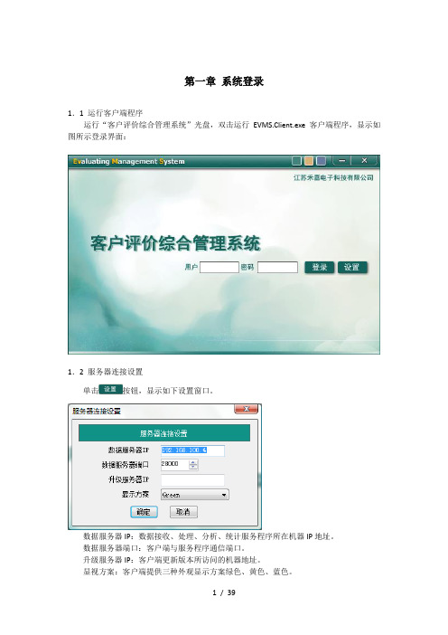
第一章系统登录1.1 运行客户端程序运行“客户评价综合管理系统”光盘,双击运行EVMS.Client.exe客户端程序,显示如图所示登录界面:1.2 服务器连接设置单击按钮,显示如下设置窗口。
数据服务器IP:数据接收、处理、分析、统计服务程序所在机器IP地址。
数据服务器端口:客户端与服务程序通信端口。
升级服务器IP:客户端更新版本所访问的机器地址。
显视方案:客户端提供三种外观显示方案绿色、黄色、蓝色。
1.3 登录在上面的登录页面输入正确的用户名和密码,初始登入账号为:admin密码:admin 单击按钮。
登录成功后系统的初始窗口如下所示:第二章系统菜单栏操作说明2.1概述本章介绍的是系统菜单栏的操作说明,在以后章节此部分将不作详细说明。
系统的公有部分主要包括三大部分:功能选择菜单机构选择树查询工具栏2.2业务查询功能选择主菜单①②③④⑤⑥⑦⑧⑨⑩○11【说明】①机构选择:选择要查看的机构,弹出如图所示窗口。
○A○b○c○A模糊搜索:用户访问机构树的快速方式。
在文本输入区输入机构的名称首字母,系统会自动搜索符合条件的机构。
在文本输入区输入机构的汉字名称,系统会自动搜索符合条件的机构。
在文本输入区输入机构的编号,系统会自动搜索符合条件的机构。
○b纵向滚动条,如果树太高,无法显示全部时会出现。
拖动可查看全部机构树。
○c点击机构名,表示当前选中了此机构。
②员工选择:选择要统计的员工,弹出如图所示窗口。
○A○b○c○A模糊搜索:用户访问员工列表的快速方式。
在文本输入区输入员工的名称首字母,系统会自动搜索符合条件的员工。
在文本输入区输入员工的汉字名称,系统会自动搜索符合条件的员工。
在文本输入区输入员工的编号,系统会自动搜索符合条件的员工。
○b纵向滚动条,如果列表太长,无法显示全部时会出现。
拖动可查看全部员工列表。
○c点击员工名,表示当前选中了此员工。
③业务选择:选择要统计的业务,弹出如图所示窗口。
○A○b○c○A模糊搜索:用户访问业务列表的快速方式。
- 1、下载文档前请自行甄别文档内容的完整性,平台不提供额外的编辑、内容补充、找答案等附加服务。
- 2、"仅部分预览"的文档,不可在线预览部分如存在完整性等问题,可反馈申请退款(可完整预览的文档不适用该条件!)。
- 3、如文档侵犯您的权益,请联系客服反馈,我们会尽快为您处理(人工客服工作时间:9:00-18:30)。
2.8.1 理解力商数(Comprehension)————————————— 20
2.8.2 持续性商数(Persistence)—————————————— 21
2.8.3 感觉/运动商数(Sensory/Motor)———————————— 21
2.9
反应时间分布图:———————————————————22 1
2.7 属性尺度(Attribute scales)—————————————— 18
2.7.1 平衡商数(Balance)————————————————— 18
2.7.2 敏捷商数(Readiness)———————————————— 19
2.8 效力尺度(Validity Scales)————————————— 19
2.5.1 警醒性商数:(Vigilance) —————————————— 16
2.5.2 注意力集中商数(Focus)——————————————— 17
2.5.3 速度商数(Speed):—————————————————— 17
2.6 多动商数——————————————————————— 17
1.2 起始界面
WINXP 操作系统启动成功以后,启动 IVA 测试软件的方法如下 双击桌面上的“IVA Test Battery”图标,弹出“IVA Test Battery Manager”对话框如下图。本界面是 IVA 软件包的起始界面, 用于完成测试软件的一些基本操作和功能选择,具体说明如下 1) 进入 点击进入按钮则进入软件操作界面。 2) 退出 点击退出按钮则退出软件系统。
IVA—CPT 报告分析与商数详解
2.1 所有商数列表————————————————————— 11
2.2 IVA 连续测试报告分析————————————————— 13
2.3 商数的定义和计算—————————————————— 14
2.4 反应控制商数 ——————————————————— 15
IVA 测试评估系统
2
1.1 概述
本手册给出了所有 IVA 商数的定义和临床分析,目的就是帮助临床医生理解 28 个 IVA 参数的起源和临床应用方法。参数被 分为四个部分:反应控制,注意力,属性和效力参数。其它还包括多动商数。IVA 的三个有效商数被用来鉴别随机反应,冲动和 疲劳反应,那些问题可能被解释为是神经综合症,情绪化倾向和学习上的一些问题。IVA 对那些能够帮助在辨别力量,虚弱程度 和越轨行为时提供帮助的有用的参数进行检测。通过本手册的学习,临床医生可以了解 IVA 是怎样反映个体的行为模式。另外 通过对商数尺度的详细分析,提供了临床诊断时的帮助。
可能导致某些功能的削弱,不利于医生作出绝对准确的判断,因此,有时候测试前需要停止服药一个星期,甚至 3-4 个星期不要 服药。
IVA 的测试结果有利于帮助决定药物的类型和药量,结合临床的经验或其它临床数据将更准确的做出决定,例如,有的测试 者通过 IVA 测试判定注意力有问题,但是并没有冲动或多动症状,则最好使用抗抑郁剂; IVA 的研究证明麻醉剂一般不能对 ADHD 有很好的疗效,相反,有易冲动的测试者使用麻醉药有较好的疗效
IVA-CPT 测试评估系统
使 用 手 册
南京伟思医疗科技有限责任公司
IVA 测试评估系统
1.1 概述—————————————————————————— 3 1.2 起始界面———————————————————————— 4 1.3 设置维护密码—————————————————————— 4 1.4 病例信息管理—————————————————————— 5 1.5 病人查询———————————————————————— 6 1.6 数据管理———————————————————————— 7 1.7 退出系统———————————————————————— 7 1.8 IVA 的测试原理————————————————————— 7 1.9 热身(Warm-up)—————————————————————8 1.10 练习(Practice)———————————————————— 9 1.11 主测试(Main IVA Test)————————————————— 9 1.12 恢复练习(Cool-down)——————————————————10 1.13 修改病人信息——————————————————————10 1.15 Investigator 详细解释——————————————————— 10 1.16 报告分析和打印(View and Print)————————————— 11
研究表明成年 ADHD 症状会影响成人每天生活的 30%-70%,这些人小时候通常多动有 ADHD 发作。成年人 ADHD 遗传率有 55%-90%,有的成年人在为孩子找医生治疗时也知道自己有 ADHD。但没有广泛认可的标准来帮助诊断成人 ADHD,ADHD 症 状在成长的过程中持续削弱,ADHD 的成年人和普通人没什么不同,对很多人来说,ADHD 诊断有着很多潜在好处,它能帮助 人们更成功更积极的生活。
2.4.1 谨慎商数(Prudence) ———————————————— 15
2.4.2 一致性商数(Consistency Auditory)——————————— 15
2.4.3 毅力商数(Stamina Auditory)————————————— 16
2.5 注意力商数————————————————————— 16
IVA 是一个包括 13 分钟声音和视觉刺激的测试系统,设计分成两个考查部分:反应控制和注意力。测试任务包括对目标或 者干扰作出反应的 500 个考验。每一个考验维持 1.5 秒钟,因而这个测试要求受测者保持不变的、持续的反应来充分的完成本测 试。IVA 的通过对 500 个测试数据的分析来帮助您来区分下面的四种 ADHD:
3.1 3.2 3.3 3.4 3.5 3.6 3.7 3.8
临床和事例分析
随意类型 ADHD 案例分析————————————————25 儿童注意力类型 ADHD 案例分析—————————————27 男童精神抑郁症类型分析———————————————— 29 女孩综合型 ADHD 类型分析 —————————————— 31 IVA 测试分析要点简述 —————————————————33 简单模式 IVA 测试诊断流程———————————————35 复杂模式 IVA 测试诊断流程———————————————36 病人自述表和行为观察分析——————————————于使孩子们迅速掌握知识的一种有效的提示,并可以大在缩短其在常规训练的时间。 在作任何结论之前,必须要在趋势线上到少找到商数间 15 分差异的事实 使用 IVA 来诊断 ADHD 必须要在药物刺激至少 2 个小时以后才能做,最好是在早晨他们使用药物之前;有的人在药刺激时,
1.3 设置维护密码
第一次使用会要求软件注册,请发送原始码给我公司工程部索取注册码。以后使用直接进入起始界面。
4
原始码 注册码
根据电脑不同而产生不同的原始码 根据原始码计算出的注册密码,每台计算机有一个唯一的注册码,经过本公司授权可以用来注册软件
IVA 主测试界面
在 IVA 起始菜单中选择 IVA Continuous Performance Test 选项,在执行 Start Program 功能按钮即可进入 IVA 主测试功能界面, IVA 测试的大部分操作都是在此功能界面完成的,下面给出本菜单的主要功能介绍。
2.10 IVA 数据分析—————————————————————22 2.10.1 简单结果分析—————————————————————22 2.10.2 复杂结果分析—————————————————————23 2.10.3 IVA 原始数据运算依据和分析—————————————— 24 2.11 IVA 适度量表 —————————————————————25
1)ADHD 注意力疏忽类型; 2)ADHD 多动神经类型; 3)ADHD 综合类型; 4)ADHD 其他类。 IVA 的分析提供六个整体合成商数和 22 个单独商数,其中两个是全面的整体合成商数,对人的状态作出最全面的评价。另 外 IVA 提供了三个特征和六个有效性商数数,将在下面讨论。因此,IVA 被设计成能帮助您做出最有效的诊断,来理解人类的 更多的自然反应和自我控制问题。 这个测试的任务要求在看到或听到“1”时按鼠标左键一次;在看到或听到“2”时不按鼠标。因此,测试者要记住下面四 条规则: 1)看到‘1‘时按鼠标左键; 2)听到‘1‘时按鼠标左键; 3)看到‘2‘时不按鼠标左键; 4)听到‘2‘时不按鼠标左键。 这些测试的反应时间情况被画成时间分布图,反映冲动和注意力不集中错误,分析产生反应和不反应的趋势。这些测试被 设计的稍微有点令人厌烦,要求测试者注意力集中。同时这个测试也向个体转移注意力的能力提出挑战。IVA 运用了数字平衡设 计,包括声音和视觉的冲动和注意力转移。 IVA 运用分析的基本原理和大多数 IQ 测试用的一样。所有的商数平均值为 100,标准偏差为 15。通过运用这种模式,IVA 使理解测试结果变的简单明了。 所有综合控制商数是基于声音反应控制商数和视觉反应控制商数的平衡点。ARCQ 和 VRCQ 得分是基于他们个人的谨慎、 一致性和毅力商数,描写如下: 1)审慎是衡量测试冲动和反应抑制的程度。错误发生在当一系列的‘1’出现后,点击了个别出现的“2”,时间和用来帮 助测试连续完成任务能力的基本可靠性。 3)毅力是用来鉴别持续注意力和错误随时间的推移。比较在测试开始和结束时不同的反应时间。 所有的注意力商数(FSAQ)基于声音注意力商数(AAQ)和视觉注意力商数的得分的平均数值。AAQ 和 VAQ 基于个人警 惕性,注意力和反应速度商数。 多动症参数起源于记录鼠标的越轨行为。这些包括:多次点击,惯性反应,猜测点击和按着鼠标键不放开。 实际上,不能够根据 IVA 测试准确无误的来判断病情,商数的有效性不能保证将难于判断病情,许多易冲动的病人将无法 完成简单的 IVA 测试,并且 ADHD 患者可能会作出古怪的反应。 许多生理和药物失调的患者有注意力和自控能力的障碍,这也会导致 ADHD 的误诊,为了得出准确的诊断,鉴别病情产生 的原因和其第二症状是必要的,因此发病程度、症状,传播情况,家族病史,攻击性原因和所有动作症状都需要结合于临床判 断。 对于小孩和青少年来说,IVA 的测试不但能够提供可以用于 ADHD 行为判断依据的客观测量数据,而且可以提供更多高质 量的脑部功能障碍方面的数据。脑受伤的,维生素缺乏的、癌症的和长期受化学毒素侵害的人,在功能性失调某些方面表现的 症状类似于 IVA,在考虑 ADHD 诊断之前要确定这些失调患者的症状是否出现在 7 岁之前。物理性失调的患者由于其在注意力 上的损害同样使其在 IVA 测试过程中表现不好,因此,对于哪些有各种失调反应的患者应在进行 IVA 测试之前进行一些常规治 疗,这有助于 ADHD 诊断 2’。 一致性测试反应可能存在听觉和视觉解释的不同,在 IVA 中允许出现在具体的商数值方面,这是因为个体在两种触觉模式 下自然反应是正确度不同,与年龄有关,被测者听觉反应时间总比视觉反应时间长,在听觉模式下出错的机率要小,因为他只 要听到说话即可,而视觉模式下被测者要全神贯注的注视屏幕。 在同一模式下强弱的表现意味着在两个商数之间至少 15 分的差别,15 分是一个标准的差距,将用于鉴别在测试中商数间差 异是否是由于主观上随机反映造成的,在作出任何判断之前最好先找出各商数之间的差异并尽力从中判断。任何一种差异都可 能被用于对病情的解释,有些人可能在某种模式下处理信息优于其他人,因此第一次学习时有些人最好告诉他怎么做,而另外 一些人可能要演示给他看,5-6 岁的小孩要么对视觉模式有反应,要么对听觉模式有反应,这种行为可以被解释为小孩对听觉或