LTJ 5270THS300型混砂车产品说明书要点
JS300型压浆台车简易说明书
JS-300型高速搅拌压浆台车使用说明书无锡市康特建筑机械有限公司研制一、主要性能参数型号JS-300Ⅳ高速搅拌部分搅拌转速1000 rpm计量精度优于1%进料容量2×0.4 m3单次搅拌量150~300kg搅拌电机型号:Y2-160M-6E,功率:7.5 kW 低速搅拌部分搅拌转速70 rpm储料筒容量0.5 m3储料电机型号:Y2-132M-4E,功率:3 kW 水泵电机型号40JDB-12压浆泵(选配件)根据用户要求行走轮规格530-240最大拖行速度10 km/h外形尺寸(长×宽×高)3500×1300×2500mm车重 1.5吨二、操作与使用1.1 参数设置当设备首次使用或长时间没有使用,或配方发生变化时,应对控制器的参数进行设置。
设置时可按下列步骤逐步进行,也可在完成某步设置后再次按一下“设置”键结束本次设置。
(1)控制器通电将电气柜内的断路开关手柄向上扳起,接通电源,面板上的红色指示灯亮。
此时控制器会先显示数字“12345”,约2秒后显示当前时间(时-分)。
(2)进入设置状态①、按一下“设置”键,时钟显示消失,“设置”指示灯闪亮;②、输入5位密码。
本机采用5位固定密码,即依次按一下“增加”、“增加”、“减少”、“减少”和“增加”按键。
每按一下按键,控制器会多显示一个“-”号。
输入完5位密码后,按一下“确认”键,如果密码正确,则控制器会显示“SET-0”,否则会退回到时钟状态。
(3)设置用水量在控制器显示“SET-0”时按一下“确认”键,控制器会显示“0-XX.X”,其中XX.X为控制器原记忆的配比中搅拌100kg水泥需要的用水量(单位为kg)。
这时可按动“增加”或“减少”键修改该值,当该值合适时再按一下“确认”键,控制器将保存该值并进入下一个设置。
(4)设置压浆剂用量在控制器显示“SET-1”时按一下“确认”键,控制器会显示“1-XX.X”,其中XX.X为控制器原记忆的配比中搅拌100kg水泥需要的压浆剂用量(单位为kg)。
100桶混砂车操作规程
100桶混砂车操作规程1 编制目的为加强安全生产工作,规范员工各项操作行为,提高员工安全操作技能,确保设备正常运转,预防各类事故的发生,结合已有规程,制定完善100桶混砂车操作使用规程。
2 适用范围本规程适用于石油、天然气压裂施工中SJC5301THS型100桶混砂车的操作与使用,其他100桶混砂车亦可参照本规程执行。
3 操作规程操作人员必须持证上岗操作人员进入施工现场必须按规定穿戴劳动保护用品。
3.1设备井场准备3.1.1混砂车应水平停放。
3.1.2压裂施工时,应确保刹车可靠,并使用不少4块驻车器掩在轮胎前后防止意外滑行。
3.1.3施工现场必须配备一定数量的消防器材,并保证消防器状态良好。
启动前的检查3.2.3.2.1行车部分3.2.1.1检查底盘发动机机油液面。
3.2.1.2检查底盘燃油箱的油量,按要求予以补充。
3.2.1.3检查分动箱和变速箱的齿轮油液面。
3.2.1.4检查各桥差速器润滑油液面。
3.2.1.5检查底盘发动机冷却液液面。
3.2.1.6检查轮胎固定螺丝。
3.2.1.7检查驾驶室的锁定。
3.2.1.8检查底盘横直拉杆,球头的连。
3.2.1.9水箱、电瓶、进气管、增压器、变速箱、发动机的固定。
3.2.1.10传动轴、中桥、后桥、拉筋、刹车分泵等的固定。
3.2.1.11确认电瓶直流供电系统是紧固的、洁净的。
3.2.1.12检查燃油软管是否开裂或泄漏,按要求予以更换。
3.2.1.13检查车架、撑臂、挡泥板、保险杠和灯光,按需要予以修理或更换。
3.2.1.14保证变速箱处于空档,并刹住卡车刹车。
3.2.2台上部分3.2.2.1检查台上发动机机油油面应在油尺的ADD与FULL 处,不足时添加同牌号油品。
FULL刻线之间并靠近.3.2.2.2检查台上发动机冷却液液面应在膨胀水箱的中部,不足时应添加同牌号的冷却液。
3.2.2.3检查台上发动机所有的气、液路管线及接头连接牢固、无松动、渗漏。
3.2.2.4检查台上发动机打气泵及发电机皮带,松紧度合适。
埃斯特顿大型砂动搅拌机说明书
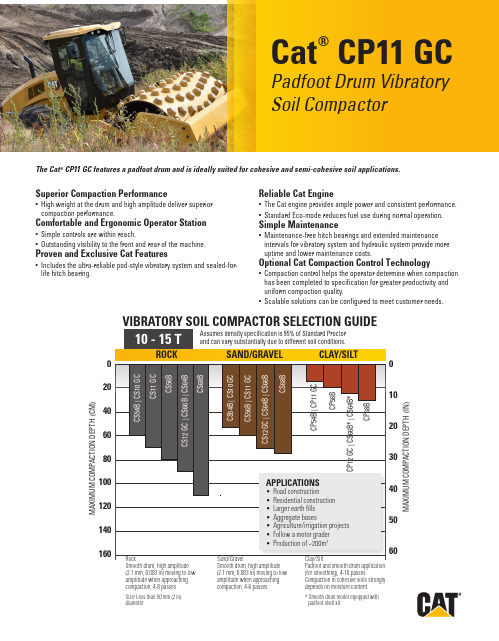
Cat ®CP11 GCPadfoot Drum Vibratory Soil CompactorThe Cat ® CP11 GC features a padfoot drum and is ideally suited for cohesive and semi-cohesive soil applications.Superior Compaction Performance• High weight at the drum and high amplitude deliver superior compaction performance.Comfortable and Ergonomic Operator Station• Simple controls are within reach.• Outstanding visibility to the front and rear of the machine.Proven and Exclusive Cat Features• Includes the ultra-reliable pod-style vibratory system and sealed-for-life hitch bearing.Reliable Cat Engine• The Cat engine provides ample power and consistent performance.• Standard Eco-mode reduces fuel use during normal operation.Simple Maintenance• Maintenance-free hitch bearings and extended maintenance intervals for vibratory system and hydraulic system provide more uptime and lower maintenance costs.Optional Cat Compaction Control Technology• Compaction control helps the operator determine when compaction has been completed to specification for greater productivity and uniform compaction quality.• Scalable solutions can be configured to meet customer needs.020406080100120140160405060ROCKSAND/GRAVEL CLAY/SIL TM A X I M U M C O M P A C T I O N D E P T H (C M )Assumes density specification is 95% of Standard Proctor and can vary substantially due to different soil conditions.Smooth drum, high amplitude (2.1 mm, 0.083 in) moving to low amplitude when approaching compaction, 4-8 passesClay/SiltPadfoot and smooth drum application (for smoothing), 4-10 passesCompaction in cohesive soils strongly depends on moisture content.Smooth drum, high amplitude (2.1 mm, 0.083 in) moving to low amplitude when approaching compaction, 4-6 passes 10 - 15 TC P APPLICATIONS• Road construction• Residential construction • Larger earth fills • Aggregate bases• Agriculture/irrigation projects • Follow a motor grader • Production of ~200m 3* Smooth drum model equipped with padfoot shell kitSize: Less than 50 mm (2 in) diameterVIBRATORY SOIL COMPACTOR SELECTION GUIDE2Nominal Amplitude - High 1.8 mm 0.071 in Frequency at High Idle 30.0 Hz 1800 vpm Frequency at Eco-Mode 28.6 Hz 1716 vpm Nominal Amplitude - Low 0.89 mm 0.035 in Frequency at High Idle 33 Hz 1980 vpm Frequency at Eco-Mode 31.5 Hz1890 vpmCentrifugal Force Maximum 249 kN 55,932 lb Minimum148 kN 33,249 lb French Classification, data/class w/ ROPS/FOPS cab39.4VM2Fuel Tank, total capacity213 L 56.3 gal Diesel Exhaust Fuel Refill Capacity 19 L 5.0 gal Cooling System 18.5 L 4.9 gal Engine Oil w/ Filter 11.6 L 3.1 gal Eccentric Weight Housings (combined)26 L 6.9 gal Axle and Final Drives 10 L 2.6 gal Hydraulic Tank (service refill)23 L6.1 galTechnical SpecificationsEngine Model Cat C3.6Global Emissions US EPA Tier 4 FinalEU Stage V Gross Power ISO 1439690.0 kW 121.0 hp Gross Power SAE J199591.7 kW 123.0 hp Net Power ISO 9249*83.7 kW 112.2 hp Net Power SAE J1349*82.9 kW 111.2 hp Displacement 3.6 L 219.7 in 3Stroke 120 mm 4.7 in Bore98 mm 3.9 in Max. Travel Speed (Forward or Reverse)11 km/h6.84 mph Theoretical Gradeability, with or without vibratioin**55%* Net power advertised is the power available at the engine flywheel when equipped with a fan at maximum speed, air cleaner, clean emissions module, and alternator.** Actual gradeability may vary based on site conditions and machine configuration. Refer to the Operation and Maintenance Manual for more information.Operating Weight w/ ROPS/FOPS canopy 11 182 kg 24,652 lb Operating Weight w/ ROPS/FOPS cab 11 344 kg 25,009 lb Weight at Drum w/ ROPS/FOPS canopy 6218 kg 13,708 lb Weight at Drum w/ ROPS/FOPS cab6264 kg13,810 lb3Dimensions1Overall Length 5.70 m 18.71 ft 2Overall Width 2.30 m 7.53 ft 3Drum Width 2134 mm 84 in 4Drum Shell Thickness 25 mm 0.98 in 5Drum Diameter (over pads)1549 mm 60.9 in 6Overall Height 3.0 m 9.8 ft 7Wheelbase 3.0 m 9.8 ft 8Ground Clearance 516 mm 20.3 in 9Curb Clearance 496 mm 19.5 in Inside Turning Radius 3.86 m 12.7 ftHitch Articulation Angle 34°Hitch Oscillation Angle15°Padfoot SpecificationsNumber of Pads 140Pad Height, oval pads127 mm 5.0 in Pad Face Area, oval pads 74.4 cm 211.5 in 2Pad Height, optional square pads 100 mm 3.9 in Pad Face Area, optional square pads 123 cm 219.1 in 2Number of Chevrons148Standard and Optional EquipmentStandard and optional equipment may vary. Consult your Cat dealer for details.Standard Optional OPERATOR ENVIRONMENTROPS/FOPS Canopy with Handrails/Guardrails,Floor Mat PVinyl Adjustable Seat, Seat Belt PAdjustable Tilting Steering Column P12-volt Power Outlet PHorn, Backup Alarm PInternal Rear View Mirror PROPS/FOPS Cab with Climate Control PDeluxe High-back Air-ride seat (Cab)PSun/Debris Shields (Canopy)PCab Internal Roll-down Sun Screen (Cab)PRear View Camera with Color TouchscreenDisplay P Sound Reduction Kit P ELECTRICAL12 volt Electrical System P150 ampere Alternator P900 Cold-cranking Amps Battery Capacity P TECHNOLOGY SOLUTIONSMeasure - Machine Drive Power P Map - SBAS GNSS Mapping P Connect - Cloud and Machine Connectivity P POWER TRAINCat C3.6 Diesel Engine, 4 cylinder PSingle Propel Pump PFuel Filter, Water Separator, Priming Pump,Water Indicator P Radiator/Hydraulic Oil Cooler PDual Braking System PTwo-speed Hydrostatic Transmission P Transmission Guard PVIBRATORY SYSTEMPadfoot Drum PDual Amplitude, Dual Frequency P Pod-Style Eccentric Weight Housings P Auto-vibe Function P OTHERProduct Link TM PSight Gauges for Hydraulic Oil Level andRadiator Coolant Level PS·O·S SM Sampling Valves: Engine Oil, HydraulicOil and Coolant P Upgraded LED Light Package P Amber Rotating Beacon PStandard Optional。
混砂车、管汇车操作规程

B-100混砂车操作规程汽车部分操作规程按照同型号汽车执行,本操作规程为特种设备部分。
1、施工前的检查和准备1.1 检查液压油面是否符合标准。
1.2 检查放火设备是否完好。
1.3 将驾驶室排挡杆换到泵档(即7档位置)。
1.4 将分动箱从行走档换到“混砂”位置。
1.5 根据施工设计要求的最大排量接好混砂车排出口到高低压管汇的软管线。
1.6 电源接通后,启动发动机。
1.7 把输砂器安全锁销摘开后,下放输砂器到地面,并垫上垫木,并使输砂斗填满砂子。
1.8 拧动输砂器开关,输砂器转动应灵活好用。
1.9 拧动混砂罐开关,混砂罐搅拌器转动应灵活好用。
1.10 按要求接好密度计并预热30分钟,按校准步骤较好密度计。
1.11 拧动各液、干添加剂开关,各泵转动灵活好用。
1.12 关闭混砂车上的所有液压传动阀(吸入阀、吸入转换阀、排出阀、排出转换阀)。
1.13 打开吸入阀、起动离心泵,达到灵活好用,打开排出阀,起动排出泵,灵活好用。
1.14 检查台上操作面板上的各种仪表显示正常,各种开关、阀门灵活好用。
2、施工作业操作:2.1 将发动机控制开关拨至台上工作位置。
2.2 选择“四种模式”的一种进行操作(其中以手动模式为常用)。
2.3 打开吸入和排出阀。
2.4 提高吸入泵转速,控制混砂罐液面,直至合适为止。
2.5 提高排出泵转速直至达到0.28Mpa。
2.6 开动搅拌器一直正常。
2.7 加砂时,开动输砂器,并根据施工设计要求进行加工和控制砂比。
3、施工作业中的检查:3.1 随时观察液压系统的工作情况,特别是温度、压力显示情况和管线有无渗漏现象。
3.2 随时观察设备各部有无异常响声和发动机水温、机油压力变化情况。
4、施工结束后的操作:4.1 将发动机控制开关拨至台上非工作位置,使发动机怠速运转8-10分钟,进行冷却发动机。
4.2 关闭吸入和排出离心泵以及歌阀门和开关。
4.3 关闭密度计放射源。
4.4 将输砂器提升到锁定位置并将安全锁销插好,放回垫木。
Daikin GC SERIES-GC300-GC550 空气和水冷机器人手册说明书

405 Front Panel Assembly - Plastic
2031460-01 P X X X
415 Side Panel-With Louvers
9051314-01 P X X X
420 Side Panel-Without Louvers (Plastic)
2101260-01 P X X X
9151087-01 REF X X X
530 Service Valve Cap
9091086-03 REF X X X
531 Service Valve Core
9091086-02 REF X X X
532 Service Valve Stem
9091086-01 REF X X X
535 TXV Assembly (Includes TXV and Tubing)
9101139-03 E X
X
220 High Temp Safety
9041087-02 E X
X
225 Ice/Off/Wash Switch
9101195-01 E X
X
230 Purge Switch
9101139-03 E X
X
235 Thermister
9101150-06 E X
X
240 Thermostatic Timer Initiate
9041071-03 WI
X
871 Water Inlet Tube (2.5 FT., 1/2 X 1/8 Clear Tubing)
6021015-02 WI X
X
WATER PUMP
880 Water Pump Assembly (With Restrictor)
SZT操作
SZT-300型二合一炉渣库侧散装机使用说明书福华通达农药科技有限公司公用事业部热电车间一、主要技术参数1.1、型号:SZT-300D1.1.1.装车能力:200t/h,最大300t/h;1.1.2.最大:300t/h物料粒度:≤25mm(90%);1.1.3.物料容重:1.45 t/m3;1.1.4.允许物料温度:≤150 ℃;1.1.5.散装头伸缩距离:3300 mm。
1.2、手动检修棒型阀门1.2.1.规格:400x400 mm.1.3、电动扇形阀门1.3.1.规格:690x690 mm;1.3.2.通过能力:300 t/h。
1.4、电动推杆1.4.1.型号: YDF-WF-222-4;1.4.2.行程:300 mm推力:7500 N ;1.4.3.速度:50mm/s功率:0.55 kW。
1.5、卷扬机1.5.1.型号:TSJ-II;1.5.2.起升速度: 8.6 m/min;1.5.3.额定起重量:25000 N;1.5.4.额定电压:380 V。
1.6、升降电动机1.6.1.型号:YEJ132S-6;1.6.2.功率:1.5 Kw。
1.7、下料伸缩钢内套筒1.7.1.规格Φ320/Φ540×4000;1.7.2.钢板厚度:8mm;1.7.3.材质:Q345 16MN耐磨钢第一节套筒加装耐磨衬套。
1.8、收尘收缩钢套筒1.8.1.规格Φ250/Φ358×4000;1.8.2.钢板厚度:4mm;1.8.3.材质:Q345 16Mn耐磨钢。
1.9、气箱脉冲袋式收尘器1.9.1.型号PPW32-4;1.9.2.处理风量:8370m³/h;1.9.3.总过滤面积:93m²;1.9.4.滤袋总数: 93条;1.9.5.滤袋规格:Φ130×2500mm;1.9.6.阻力:1470~1770Pa;1.9.7.承受负压:<5000Pa;1.9.8.入口浓度:<200g/m³;1.9.9.出口浓度:≤30~50mg/N m³;1.9.10.供气压力:0.5~0.7MPa;1.9.11耗气量:0.46m³/min。
wl300说明书

图 3-
2.引脚端子名称
2
表 3-1
上 插座编号
EA S+ SE+ EST COM
侧 编号含义 屏蔽地 信号正 信号负 桥源正 桥源负 生产启动 地电位
N
220V 交流电源
PE
屏蔽地
L
220V 交流电源
3-4 通讯口接线
下 插座编号 SG RXD TXD GND TO CLE SL FA M4 M3 M2 M1 POW
10
图 4-5
当显示“
”时,按
键选择“
”或“
”,“
”
表示连续方式,即仪表不需要上位机的命令,就能不停的上传当前的净重;“
”表示
指令方式,即仪表只有接收到上位机的命令,才执行相应的通讯功能,另外, 最后必需有回 车结束符。
指令列表
指令 指令格式
指令说明
启动生产
66B
“B”为启动生产命令, 66 为“B”命令的校验和
(小数点在第 1 位置时不显示) (7)量程
键进入下一功能设置项。
当显示“
图 4-8
”时(如图 4-8),按
键和
键选择 1 至 8000 中某一数值,
该数值表示最大称重量,随后按 (8)零位范围
键进入下一功能设置。
当显示“
图 4-9
”时(如图 4-9),按
键和
键选择 0.1 至 9.9 中某
一个数值,该数值表示零位范围在总和中所占百分比,随后按 置项。
11.显示区一 12.显示区二
如果初始调校的零位漂移不大于归零范围,又没有检测到重量变
动,按下该键显示器显示零。 显示区一在称重状态显示净重,在运行状态上料时显示该种料的 实际上料量,卸料时显示净重。 显示区二在称重状态显示毛重,在运行状态上料时显示该种料的, 卸料时显示毛重。
Trencher TH300 操作手册说明书

WARNING: If incorrectly used this machine can cause severe injury. Those who use and maintain this machine should be trained in its proper use, warned of its dangers and should read the entire manual before attempting to set up, operate, adjust or service the machine.OWNER/OPERATOR’S MANUAL & ILLUSTRATED PARTS LIST09-346 REV BMODEL:73-70920TRENCHER TH300CALIFORNIAProposition 65 Warning Diesel engine exhaust and some of its constituents are known to the State of California to cause cancer, birthdefects and other reproductive harm.Californie Proposition 65Avertissement Les échappements des moteurs diesel et certains de leurs composés sont reconnus par l’Etat de Californie pour être cancérigènes, provoquer des défauts congénitaux et d’autres dangers en matière de reproduction.ADVERTENCIAAVERTISSEMENTWARNINGThe engine exhaust from this product contains chemicals known to the State of California to cause cancer, birth defects or other reproductive harm.California Advertencia de la Proposicion 65El estado de California hace saber que los gases de escape de los motores diesel y algunos de sus componentes producen cáncer, defectos de nacimiento y otros daños en el proceso de reproducción humana.L’émission du moteur de ce mat ériel contient des produits chimiques que l’Etat de Californie consid ère être canc érig ènes, provoquer des d éfauts cong énitaux et d’autres dangers en mati ère de reproduction.El estado de California hace saber que los gases de escape de este producto contienen productos quÍmicos que producen cáncer,defectos de nacimiento y otros daños en el proceso de reproducción humana.© 2003, TEXTRON INC1TRENCHERIMPORTANT MESSAGEThank you for purchasing this Jacobsen product. You have purchased a world class product, one of the best designed and built anywhere.This product comes with an Owner/Operator's Manual. The useful life and good service you receive from this product depends to a large extent on how well you read and understand this manual. Treat this product properly and adjust it as instructed, and it will give you many years of reliable service.See a Jacobsen dealer for any service or parts needed. Jacobsen service ensures that you continue to receive the best results possible from Jacobsen products. You can trust Jacobsen replacement parts because they are manufactured with the same high precision and quality as the original parts.Jacobsen designs and builds its equipment to serve many years in a safe and productive manner. For longest life, use this product only as directed in the manual, keep it in good repair and follow safety warnings and instructions. You'll always be glad you did.Jacobsen, a Textron CompanyOne Bob Cat LaneJohnson Creek, WI 53038-04691-2005TABLE OF CONTENTS FIGURES PAGE DESCRIPTION / SPECIFICATIONS..............................................................................................................2SAFETY .....................................................................................................................................................3, 4INSTALLATION ..............................................................................................................................................5OPERATION ..................................................................................................................................................6SERVICE .......................................................................................................................................................7MAIN FRAME & SHIELDS.................................FIGURE 1.....................................................................8, 9DRIVE PARTS ...................................................FIGURE 2..................................................................10, 11BOOM & CHAIN ASSEMBLY.............................FIGURE 3.................................................................12, 13HYDRAULICS....................................................FIGURE 4.................................................................14, 15GEAR BOX ........................................................FIGURE 5.................................................................16, 17CRUMBER.........................................................FIGURE 6.................................................................18, 192TRENCHERDESCRIPTION / SPECIFICATIONSSPECIFICATIONSOverall Width ...............................................................................37"Overall Height..............................................................................34"Overall Length .............................................................................64"Total Weight ................................................................................395 lbs.Auger Diameter............................................................................12"Chain Speed ................................................................................550 ft./min.Drive Shaft (diameter).................................................................1-1/2"Cutting Depth (max)....................................................................28"Cutting Width ...............................................................................4-3/4"DESCRIPTIONThe trencher is designed to perform with the Steiner 4-wheel drive articulated frame steering tractors. The trencher mounts on the quick hitch front lift in the conventional manner. Driven by a PTO belt, a right angle gearbox provides a 2 to 1 reduction providing power to the trencher digging chain. The depth of trench is regulated by a cylinder controlled by the auxiliary hydraulic system of the power unit.Features include:•Visible depth indicator.•Front mount Quick Hitch.•Variable depth control.•High performance bearings throughout.•Quick chain tension adjustment.•Heat treated carbide tip chain.Trencher easily follows line of trench, cutting to a maximum depth of 28 inches. The depth of cut is easily adjustable during operation indicated by the highly visible depth gauge.3TRENCHERSAFETYNOTICEUnauthorized modifications may present extreme safety hazards to operators and bystanders and could also result in product damage.Jacobsen, a Textron Company strongly warns against, rejects and disclaims any modifications,add-on accessories or product alterations that are not designed, developed, tested and approved by Jacobsen Engineering Department. Any Jacobsen product that is altered, modified or changed in any manner not specifically authorized after original manufacture–including the addition of “after-market”accessories or component parts not specifically approved by Jacobsen–will result in the Jacobsen Warranty being voided.Any and all liability for personal injury and/or property damage caused by any unauthorized modifications,add-on accessories or products not approved by Jacobsen will be considered the responsibility ofthe individual(s) or company designing and/or making such changes. Jacobsen will vigorously pursue full indemnification and costs from any party responsible for such unauthorized post-manufacture modifications and/or accessories should personalinjury and/or property damage result.This symbol means:ATTENTION!BECOME ALERT!Your safety and the safety of others is involved.Signal word definitions :The signal words below are used to identify levels of hazard seriousness. These words appear in thismanual and on the safety labels attached to Jacobsen machines. For your safety and the safety of others, read and follow the information given with these signal words and/or the symbol shown above.DANGER indicates an imminently hazardous situation which, if not avoided, WILL result in death or serious injury.WARNING indicates a potentially hazardous situation which, if not avoided, COULD result in death or serious injury.CAUTION indicates a potentially hazardous situation which, if not avoided, MAY result in minor or moderate injury. It may also be used to alert against unsafe practices or property damage.CAUTION used without the safety alert symbol indicates a potentially hazardous situation which, ifnot avoided, MAY result in property damageSAFETYTRENCHERGENERAL SAFETY1.Read and understand the Owner’s Manual before attempting to operate this machine.2.Operate all controls from the operator’s seat. NO RIDERS.3.Keep all shields in place and safety switches adjusted properly.4.Do not leave equipment unattended. STOP the engine and remove the key.5.Do not allow minors or the inexperienced to operate this machine.6.Keep people and pets a safe distance away from machine using power driven attachments. Injurycould result from flying debris.4TRENCHERINSTALLATIONMOUNTING INSTRUCTIONSThe trencher should be used only on Steiner4-wheel drive power units equipped with hydraulic auxiliary couplers.To mount the trencher do the following steps: 1.Open quick hitch latches. Drive tractor intoposition, aligning the quick hitch. Be sure thatboth latches are fully engaged and locked.2.Stop engine to install drive belt. See power unitoperator’s manual for drive belt installation and tension adjustment.3.Remove clip pin from support stand and raisestand to transport position. Secure stand withclip pin.4.Connect hydraulic hoses to the auxiliarycouplers. If auxiliary hydraulic lever seems tooperate in the wrong direction, connect thehoses in the opposite couplers.UNMOUNTING INSTRUCTIONS1.Choose a level site to remove the trencher.2.Lower the support stand and secure with clippin.3.Lower the front lift. Lower the boom and applyslight down pressure.4.Set parking brake and stop engine.5.Disconnect hoses from the quick couplers.6.Remove drive belt.7.Open quick hitch latches. Start engine andback power unit away from the trencher.5OPERATIONTRENCHER6TRENCHERSERVICESERVICE SCHEDULEEvery 4 Hours:•Grease the boom pivot tube.Daily:•Check for any signs of loose bolts and tighten as needed.•Check digging chain for missing or broken cutters. Repair as needed. Check diggingchain tension.•Wash boom, digging chain and auger at the end of each workday.25 hour:•In addition to daily service, lubricate the roller chain with chain lube or SAE 30 motor oil.•Check gearbox oil level. Oil level is 4 inches down from the top of filler tube. Use #90 gearoil.100 hour:•Change gearbox oil at 100 hours or four weeks initially, and every 2500 hours or sixmonths of operation thereafter. Use #90 gearoil.ADJUSTMENTSDrive belt tension:•See the power unit operators manual foradjustment of drive belt tension.Roller chain drive:•Adjustment is by a spring loaded idler.Digging chain tension:•Adjust with large set screw in the center of boom. Loosen jam nut and tighten set screwuntil chain has 1/4 inch to 1/2 inch gap whenlifted from the boom at mid—point. Tightenjam nut.Crumber adjustment:•The crumber should be close to, but nottouching, the digging chain at any time. Theunit may need to be moved out as the diggingchain stretches. Choose from three mountinghole positions.NOTE:DO NOT OVERTIGHTEN CHAIN. This will cause undue wear on the boom components.Replacing digging chain:1.Loosen four bolts through the boom.2.Loosen jam nut on the set screw in the center ofthe boom and back out the set screw to allowthe boom to retract.3.Remove the old chain and replace with the newchain.4.Tignten the set screw until the chain is snug.Tighten the jam nut. Tighten the bolts that wereloosened in Step 2.5.Check new digging chain tension (as describedabove) after it has run for 20 minutes, and everyhour of use for the next 4 hours.NOTE: It is normal for a new chain to require frequent tightening.7MAIN FRAME & SHIELDSTRENCHERFIGURE 18TRENCHERITEM PART NO.DESCRIPTIONQTYITEMPART NO.DESCRIPTIONQTYMAIN FRAME & SHIELDSFIGURE 11-162-823.7MAIN FRAME 1*4116761LBL-MADE IN USA 11-260-625.7SHIELD-AUGER 1*00-223LBL-DANGER STAND CLEAR11-344-140DEFLECTOR BELTING, DIRT 11-464139-08BOLT-5/16-18X3/451-564141-6NUT, 5/16-1851-644-141BELTING, AUGER 11-764-855STRAP, BELTING 11-864123-75BOLT, 3/8-16X3 HEX 31-964141-4NUT-WLF 3/8-16101-1064139-24BLT-WLF 3/8-16 X 141-1164-849CLAMP, BELTING 11-124134161TUBE AND HOSE CLMP 1/4"21-1301-014SCREW, MACHINE 8-32 X 111-1464025-29NUT-HEX #8-32 KEPS 21-1564-834.7FOOT STAND W/A 11-1664123-87BOLT-HEX 3/8-16X1-3/411-1764229-03LOCKNUT-NYLON 3/8-1611-1803-0616CLEVIS PIN, 3/8 X 211-1902-PP0313PIN, 3/16 x 1.5/811-2060-626.7SHIELD, DRIVE BELT 1*00-025LBL-HANDS & FEET 11-2190-0808BOLT 41-2264163-67WASHER-.516X1X12GA 41-2364006-05LOCKWSHR-HELICAL 1/241-2464139-02BLT-WLF 1/4-20X1/271-2564141-2NUT-WLF 1/4-2011-2664-848.7BRACE, CHAIN SHIELD 11-2760-624.7GUARD, CHAIN 1*00-093LBL-WARN OWNR MAN 1*00-223LBL-DANGER STAND CLEAR11-2864139-21BLT-WLF 3/8-16X3/431-2960-628.7COVER, CHAIN GUARD 1*00-217LBL-MODEL TH3001*00-223LBL-DANGER STAND CLEAR11-3060-629.7COVER, ACCESS 11-3164123-89BOLT-HEX 1/4-20X3/411-3264163-03WSHR-.256ID X.62OD X 1811-3364229-01LOCKNUT-NYLON 1/4-2011-3464-851.7CLAMP, BOOM SWIVEL 11-3564229-02LOCKNUT-NYLON 5/16-1821-3664163-02WSR-.321/.328X.593/.608X1141-3764123-55BLT-HEX 5/16-18X321-3864-847.7CLAMP, BELTING 11-3944-142BELTING, RUBBER 11-4064-861.7STRAP, AUGER BELTING 11-4164152-618-32 X 1 1/4 MACH SCRW 2* NOT ILLUSTRATEDDRIVE PARTSTRENCHER FIGURE 2TRENCHERITEMPART NO.DESCRIPTION QTYITEM PART NO.DESCRIPTION QTYDRIVE PARTSFIGURE 22-162-823.7FRAME, MAIN W/A12-280-192.7AUGER, TRENCHER W/A 12-3CLAMP-AUGER1(SUPPLIED W/64-836)2-464123-171BOLT-HEX 3/8-16X3-1/222-564229-03LOCKNUT-NYLON 3/8-1622-664164-26KEY-3/8x3/8x1-1/2 SQ 32-764-854SPACER-AUGER 1(USED WITH STANDARD DIGGING CHAIN)64-924SPACER-AUGER 1(USED WITH 5-1/2" CHAIN KIT)2-883-041DRV SPRKT-W/ 3/8 KEYWAY 12-960-630.7SHIELD22-1055-1108KRR BRG-FAFNIR W/COLLAR 12-1180-253SHAFT-DRIVE12-1255-RA108RR BRG-FAFNIR W/COLLAR 12-1360-624.7GUARD, CHAIN 12-1487-175GEARBOX, RIGHT ANGLE 12-1529-079PIPE NIPPLE, 1/2 X 1.1/212-1624-033PIPE CAP, 1/2"12-1783-BK85H PULLEY-8.5" H1 BUSHING 12-18D3032BUSHING, H 7/812-1964164-11KEY-3/16X3/16X1-1/4 SQ 12-2081-B050BELT-B511(USED ON 415 & 430)2-2164006-05LOCKWSHR-HELICAL 1/252-2290-0808BOLT42-2383-60Q40SPROCKET, 60Q4012-2456-RC60-42CHAIN-#60 42"181-024CONNECTOR LINK #60181-077HALFLINK-#6012-2583-Q124BUSHING-Q1 X 1-1/2"12-2683-H601220SPRKT-FIXED BORE 1-1/412-2764164-101/4X1/4X1-1/4 MACH KEY 12-2840-322.7ARM, IDLER12-2983-6015E08IDLER SPRKT #60 15TTH 1/212-3085-B29BUSHING,.406 X.740 X.25812-3141-020SPRING12-3264123-70BOLT-HEX 3/8-16X1-1/212-3364123-50BOLT-HEX 3/8-16X112-3464123-24BLT-HEX 1/2-13X212-3564163-61WSHR .81X.406X16GA 22-3664163-67WASHER-.516X1X12GA 22-3764025-09HEX, NUT 1/2-1312-3864141-4NUT-WLF 3/8-1632-3956-068TRIM SEAL 12"1BOOM & CHAIN ASSEMBLYTRENCHER FIGURE 3TRENCHERITEM PART NO.DESCRIPTIONQTY ITEM PART NO.DESCRIPTIONQTY BOOM & CHAIN ASSEMBLYFIGURE 33-162-821.7BOOM1(INCLUDES ITEMS 4 - 11)3-290-0826BOLT,1/2-13 X 3-1/443-364141-13NUT WLF 1/2-1343-492-12NUT,3/4-1013-585-105-372SET SCREW-3/4 X 513-687-105-379BOLT-3/4 X 1-1/413-787-110-054BUSHING 23-887-115-464SNAP RING 13-987-142-755ROLLER 13-1087-125-009BEARING13-1187-183-469IDLER SHAFT 13-1279-080CHAIN-DIGGING 4-3/4"1(STANDARD)*70-125KIT-3-1/2" TRENCHER CHN 1(OPTIONAL)62-861CRUMBER WLDMT 179-098CHAIN-3-1/2" WIDE 1*70-117KIT-5-1/2" TRENCHER CHN 1(OPTIONAL)64-924SPACER-AUGER 179-099CHAIN-5-1/2" WIDE13-1/2" CHAIN REPAIR LINKS3-1379-090REPAIR SECTION 1(CENTER CUT)3-1479-091REPAIR SECTION 3"1(LH STRAIGHT)3-1579-092REPAIR SECTION 3"1(RH STRAIGHT)3-1679-103REPAIR SECTION 1(OFFSET LEFT)3-1779-104REPAIR SECTION 1(OFFSET RIGHT)3-1879-102REPAIR SECTION 1(3-1/2" DOUBLE)4-3/4" CHAIN REPAIR LINKS *79-101REPAIR SECTION 1(4-3/4" DOUBLE)5-1/2" CHAIN REPAIR LINKS *79-093REPAIR SECTION 1(4" DOUBLE)*79-095REPAIR SECTION 1(5" DOUBLE)*79-096REPAIR SECTION 1(5-1/2" DOUBLE)* NOT ILLUSTRATEDHYDRAULICSTRENCHER FIGURE 4TRENCHERITEM PART NO.DESCRIPTIONQTY ITEMPART NO.DESCRIPTIONQTYHYDRAULICSFIGURE 44-123-070CYLINDER, HYD. 2 X 8121-13055X SEAL KIT14-264-852TOP PIN14-302-CP0512COTTER PIN, 5/32 X 1-1/244-425-2103-6-6 FITTING-90 DEG.24-520-017HOSE-1/4 X 7024-625-0103-4-6 FITTING-STR 24-723-004MALE QUICK COUPLER 24-864-853BOTTOM PIN 14-964-846SPACER, DEPTH GAUGE 14-1064-839.7DEPTH GAUGE W/A 14-1102-CP0410COTTER PIN, 1/8 X 1-1/414-1256-073GAUGE, DEPTH14-1362-822.7FRAME, BOOM PIVOT W/A 14-1464-835.7SAFETY TUBE W/A 100-224LABEL3(DANGER FOR TRENCHER)4-1599-K56BOLT-FLANGE 1/2-13X1-1/244-1664141-13NUT WLF 1/2-1344-1729-010S/B GREASE FITTING 1GEAR BOXTRENCHER FIGURE 5TRENCHERITEM PART NO.DESCRIPTIONQTYITEMPART NO.DESCRIPTIONQTYGEAR BOXFIGURE 55-187-CM000182 HOUSING 15-287-CM450064 COLLAR 15-387-CM150144 BEARING CUP 25-487-CM150136 BEARING CONE 25-587-CM370023 SHIM (.010) VARIES 5-687-CM370015 SHIM (.005) VARIES 5-787-CM620062 RETAINING RING 15-887-CM410233 LOCKWASHER 15-987-CM410255 LOCKNUT 15-1087-CM600031 KEY 15-1187-CM050237 HUB 15-1287-CM450585 COLLAR 15-1387-CM620088 RETAINING RING 15-1487-CM200287 SHAFT 15-1587-CM300251 SEAL 15-1687-CM150151 BEARING CONE 15-1787-CM150011 BEARING CUP 15-1887-CM410163 SEMS CAP SCREW 165-1987-CM390021 GASKET (.015)15-2087-CM390039 GASKET (.005)15-2187-CM390195 GASKET (.003)15-2287-CM101030 GEAR 15-2387-CM055327 THRU CAP 15-2487-CM452326 COLLAR 15-2587-CM600171 KEY 15-2687-CM222810 THRU SHAFT 15-2787-CM301473 SEAL 15-2887-CM150557 BEARING CONE 15-2987-CM150540 BEARING CUP 15-3087-CM101048 PINION 15-3187-CM410027 PIPE PLUG (SOLID)25-3229-079PIPE NIPPLE, 1/2 X 1.1/215-3324-033PIPE CAP, 1/2"1CRUMBERTRENCHER FIGURE 619TRENCHERITEM PART NO.DESCRIPTION QTY ITEM PART NO.DESCRIPTION QTYCRUMBER FIGURE 66-164-858.7PLATE-CRUMBER SIDE 26-264229-05LOCKNUT, 1/2-13 NYLON 66-390-0826BOLT,1/2-13 X 3-1/446-462-825.7LINK-TOP WLDMT 16-562-826.7LINK-BOTTOM WLDMT 16-664123-72BLT-HEX 1/2-13X2-1/226-762-824.7WLDMT-CRUMBER 1(USED WITH STANDARD DIGGING CHAIN)62-861.7WLDMT-CRUMBER 1(USED WITH 3-1/2" CHAIN)Equipment from Jacobsen, a Textron company,is built to exacting standards ensured byISO 9001 and ISO 14001 registration at all ourmanufacturing locations.A worldwide dealer network and factory-trainedtechnicians backed by Textron Parts Xpressprovide reliable, high-quality product support.BOB-CAT BROUWER BUNTON CUSHMAN RYAN STEINER。
- 1、下载文档前请自行甄别文档内容的完整性,平台不提供额外的编辑、内容补充、找答案等附加服务。
- 2、"仅部分预览"的文档,不可在线预览部分如存在完整性等问题,可反馈申请退款(可完整预览的文档不适用该条件!)。
- 3、如文档侵犯您的权益,请联系客服反馈,我们会尽快为您处理(人工客服工作时间:9:00-18:30)。
特别提醒:注意安全!规范操作!1.调整和检修发动机、离合器、分动箱及各传动部件等之前,务必先停止发动机;2.操作混砂车时不允许拆下仪表或护罩;3.操作人员进入井场,应戴安全帽,穿好劳动防护用品;4.加注发动机燃油时,严禁明火及吸烟;5.启动前检查车台传动系统、控制系统、电器仪表系统、液压系统等安装是否正确无误,各管线连接是否正确;6.设备处于运行状态时,不得将手、脚或其它物件放入混合罐、输砂器、泵和其它传动机械装置内。
以防造成设备和人身事故;7.设备运行中如发生意外停车,应立即重新启动,以免损坏柴油机涡轮增压器;8.发动机启动后,不宜立刻加载运行,应空载运行一段时间,待各部温度正常,润滑情况良好后,方可进行施工运行;9.施工完成后,需将控制各部运转的电位器旋钮置于关闭状态(零位),关闭仪表电源和总电源开关;10.每次作业后,操作人员必须按说明书要求逐一进行认真检查,同时还要冲洗连接管路、液添泵、混合罐,并将连接管路、混合罐等处内的液体排尽。
1.设备型号名称及使用范围2.设备主要性能参数2.1总体性能参数2.2载重汽车2.3台上发动机2.4分动箱2.5清水泵2.6砂泵2.7混合罐2.8螺旋输砂器2.9液体添加剂泵3.结构简述3.1传动系统3.2管路系统3.3液压系统3.4吸入泵及排出泵3.5混合罐及搅拌混合系统3.6螺旋输砂器3.7液添泵装置3.8气控系统3.9电器系统3.10操纵室3.11仪表与控制4.操作程序说明4.1施工前的准备和试运转4.2加砂压裂施工作业4.3停车程序5.维护、保养注意事项6.有关资料及附表设备型号名称:LTJ 5270T HS300型混砂车型号说明:LTJ—企业代号(兰州通用机器制造公司)5—专用车代号27—产品质量规格(约27吨系列)0—设计顺序号T—特种用途车辆HS—混砂车300—最大输砂量为300M3/h使用范围:本设备为车载式,能适合无等级路面行驶,并适用于粗糙路面、风沙灰尘、泥泞的油田环境。
该设备具有能够在零下30℃之40℃的环境温度范围内满负荷连续工作6小时以上的能力。
适用于配置各种不同添加剂的压裂液,可向各型压裂车泵送不同砂比、不同粘度的压裂液,完成大、中型压裂施工。
2.设备主要性能参数2.1总体性能参数砂泵最大排量16m3/min(清水性能)最大排出压力0.6MPa最大输砂量 5 m3/min最大砂比45%(体积比)车装外形尺寸(长×宽×高):11990×2500×3970mm设备总重约27310kg2.2载重汽车型号北方奔驰ND1313D50J载重底盘汽车(国Ⅳ)驱动形式8×4轴距1500+5050+1450发动机型号WP10.336E40型直列水冷增压中冷柴油机最大功率247KW(336HP)/2200r/min最大扭矩1160N·m/1300~1500 r/min最大总质量31000kg2.3台上发动机型号V olvo TAD1642VE额定输出功率494KW(672HP)额定转速1800r/min最大扭矩3150N·m/1200~1500 r/min尾气排放符合欧洲COME环保标准其它配套3A-356重型摩擦离合器(手动+气动)2.4分动箱输入功率500KW输出功率500KW传动比i入—出=1啮合方式圆柱斜齿轮常啮合式润滑方式强迫式2.5清水泵型号MISSION 10″×8″×14″最大排量12M3/min(清水性能)排出压力0.5MPa2.6砂泵型号YX—12″×10″×17.5″最大排量16 M3/min/(1750r/min)(清水性能)最大排压0.6MPa2.7混合罐形式立式圆锥夹套罐,水力+机械搅拌容积 2.5M32.8螺旋输砂器形式双筒螺旋输砂器,整体升降,独立开分(最大开分角70°)最大输砂量 5 M3/min输砂绞龙转速0~400r/min2.9液体添加剂泵(三组)液添泵ⅠB300C耐腐齿轮泵排量0~250L/min压力 1.2MPa转速0~1000 r/min液添泵Ⅱ三缸活塞泵排量0~34L/min压力5MPa转速0~780r/min液添泵Ⅲ三缸活塞泵排量0~42L/min转速0~660r/min3.结构简述3.1传动系统传动系统由台上发动机、离合器、分动箱和液压传动构成,台上各执行元件采用全液压传动。
台上柴油机经离合器、弹性柱销联轴器驱动分动箱。
分动箱是整个动力传动的中枢,它由一个输入轴和两个输出轴及齿轮、箱体、法兰所组成。
输入输出轴分别串接液压泵,驱动各个执行机构。
分动箱有三个输出口,分别驱动4个闭式变量泵、1个负载式变量泵和1个齿轮泵。
4个闭式变量泵分别驱动吸入泵、排出泵和两个输砂绞龙,1个负载变量泵和齿轮泵通过阀组驱动辅助系统,为液添泵、搅拌、液压油的冷却散热器提供动力,以及完成输砂器的起升、分合、液位油缸控制,作业时均为台上取力,不需要发动底盘汽车。
3.2管路系统3.2.1管路形式双吸双排结构(10吸12排或12吸10排),通过启闭管汇中相应的隔断阀确定管路吸入、排出,便于施工联接。
整个系统由吸入排出泵、吸入排出管汇、管系及蝶阀等附件组成,主吸入排出管为8″。
吸入排出口均为4″(公制T165×16)油壬凹接头。
3.2.2吸入泵及管路吸入泵装在设备的副驾驶前侧,由液马达驱动,该泵可最大以12M3/min 的流量向混砂罐供液。
主吸入管汇共有10个进液口,安装在底盘汽车副驾驶侧中部,每个进液口配有4″手动蝶阀及快速接头。
在吸入泵主排出管路上装有一8″涡轮流量计(双探测头接口),流量计上带相应的传感器和电缆将排量信号传递到操纵室仪表台上,用以计量供给液量(清水)。
另外,在主进液管路装有液控蝶阀,可实现清水供给的启闭。
施工中不仅可以通过手动调整水泵转速控制液面,也可临时通过进水蝶阀调整清水供给。
3.2.3排出泵及管汇排出系统由排出泵、排出管汇、蝶阀及流量计组成。
主排出管汇共有12个排液口,安装在底盘汽车主驾驶侧中部,每个排液口配有4″手动蝶阀及快速接头。
在砂泵主排出管路上装有一8″涡轮流量计(双探测头接口),流量计上带相应的传感器和电缆将排量信号传递到操纵室仪表台上,用以计量排出液量(混合液)。
另外,在排出主管线上还装有一4″砂泵排空返回管,用于压裂开始时砂泵内空气的排放及排出液的回流取样等。
3.3液压系统液压系统由一个油箱、一个负载变量泵、四个闭式变量泵、一个齿轮泵及进口产品,元件性能可靠、操作控制方便,以上元件构成4个闭式电液比例控制(EP)液压系统和1个开式负载敏感(LS)控制液压系统。
其中,闭式系统通过电位计和泵比例伺服器可以有效控制吸入泵、排出泵及左右输砂绞龙转速,以保证压裂施工的质量。
开式负载电控系统可准确控制搅拌器、液添泵的转速和转向、马达、油缸、散热器等,该系统的所有执行机构均通过负荷多路阀块进行电液比例调速及换向控制。
液压油箱的容积为1m3,并装有吸入、排出精滤器(10μm),蝶阀、液位计及污染报警。
主要元件组成负载变量柱塞泵A11VODRS系列闭式变量柱塞泵A4VG系列齿轮泵1PF2系列斜轴马达A2FM系列径向柱塞马达GM3系列摆线马达OMT、OMP系列多路阀块M4—15系列升降、开分液缸HSG系列控制功能:手动电比例调速,可实现各液压马达的无级调速及正反转(正反转功能水泵、砂泵除外)。
输砂器系统输砂绞龙轴由装在输砂器顶部的两个径向柱塞液压马达直接驱动。
当台上发动机以1800r/min转速通过分动箱驱动液压泵时,两个输砂马达能以最大400r/min的转速旋转。
在电位计调整下,输砂绞龙轴能在5~400r/min范围内任意速度进行正向或反向、独立或同时旋转。
输砂器起升、分合系统输砂器起升、分合系统用来提升和降落、展开和闭合输砂器。
它是利用弹簧复位式比例先导阀控制多路阀实现操纵各个液缸来实现的,并且油缸伸缩速度可以通过手柄控制角度大小调整。
当输砂器起升至行车位置时,由两个插销轴将输砂器位置锁定保证行车安全。
砂泵、水泵系统由液压马达驱动离心式砂泵、水泵,通过仪表台上的电位计调节液压马达的转速,控制离心泵流量或压力的大小。
液体添加剂系统液体添加剂系统由液添泵、吸入管系、计量装置及排出管系组成。
液体添压马达的转速,以达到控制液体添加量的大小。
搅拌系统搅拌器位于混合罐中部,通过仪表台电位计来控制搅拌马达的转速,调节转速在0~250r/min之间工作。
3.4吸入泵及排出泵泵结构为半开式叶形混流泵。
叶轮前部为叶形空间扭曲形叶片形式,后部为平面曲线展开形副叶片形式,结构紧凑,体积小、排量大。
叶轮、泵体,磨板等主要磨损件均为合金铸铁,具有很高耐磨性。
局部磨损后允许补焊,但必须保持所焊表面曲线不变。
3.5混合罐及搅拌混合系统混合罐外观为立式流线型圆锥夹套罐。
清水由罐的夹套内切向进入,混合液由罐的内腔经搅拌混合后通过砂泵吸出。
罐内腔侧壁上、下部均为涡流导砂板结构,罐体夹层中部有一圈2″液压冷却钢管,用于部分液压油的冷却,中部为螺旋桨形立式叶片(双层)搅拌器。
下部锥形圆底结构主要克服了沉砂现象。
当清水、支撑剂、压裂砂等进入罐内,搅拌器启动,罐内形成的水力搅拌及机械搅拌使砂液形成紊乱涡流状态并进行充分混合,具有混合均匀、无沉砂、无飞溅的特点,有利于进行大砂比的施工。
3.6螺旋输砂器螺旋输砂器部件由输砂绞龙外壳、砂斗、输砂铰龙轴、输砂器支座、液压马达支座、起升托座等组成。
输砂铰龙轴为液力驱动,可分别无级调速及正反转,铰龙轴由钢板卷制叶片并与钢管焊接而成。
输砂器最大开分角为70°,每个输砂器能以最大35°展开角进行独立开合。
该输砂器的控制采用独立的工作方式,在输砂量小于0.75M3/min时,可使用单筒工作。
砂斗距地面高度不大于0.85米,输砂器起升到合适位置后由销轴插入支撑板中锁定输砂器。
铰龙轴上部装有信号检测计量齿盘,通过传感器和电缆将输砂信号传递到仪表台和仪表车上。
瞬时砂量、累计砂量及砂比可从仪表台的数显仪直接读出。
3.7液添泵装置该装置固装在汽车尾部两侧,系统由液添泵、液压马达、联轴器、流量计、一个针式止回阀、马达支座以及管汇件等组成。
液添系统由低速大扭矩液压马达直接驱动耐腐齿轮泵,泵管线入口为2″,排出口通过流量计注入胶联集流管,从集流管各处口分别泵入混合罐(罐内胶联)及排出管汇中(管汇胶联)。
3.8气控系统系统由汽车气包、离合汽缸及各气控阀和气管路组成。
台上与汽车共用一个气包,气包出口1/4″球阀的开关实现台上供、断气,并通过在操纵室控制3.9电器系统电器系统主要包括控制台上发动机、照明、液压电控系统、仪表计量系统等。
电源供给为24V直流电,由汽车电瓶及台上电瓶共同提供。